Table of Contents

Related Manuals for Toro 04044


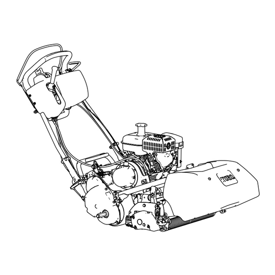
Summary of Contents for Toro 04044
- Page 1 Form No. 3422-731 Rev B Greensmaster ® Flex ™ 1820 and 2120 Traction Unit Model No. 04044—Serial No. 403070001 and Up Model No. 04045—Serial No. 403070001 and Up *3422-731* B Register at www.Toro.com. Original Instructions (EN)
- Page 2 Declaration of Conformity (DOC) sheet. Whenever you need service, genuine Toro parts, or It is a violation of California Public Resource Code additional information, contact an authorized Toro...
-
Page 3: Table Of Contents
Contents Servicing the Traction-Interlock Switch ..............31 Servicing the Brake-Interlock Switch....32 Safety ............... 4 Brake Maintenance ..........32 General Safety ........... 4 Adjusting the Service/Parking Brake....32 Safety and Instructional Decals ......4 Belt Maintenance ..........33 Setup ................ 7 Inspecting the Reel-Drive Belt...... -
Page 4: Safety
Safety • Do not operate the machine without all guards and other safety protective devices in place and working on the machine. This machine has been designed in accordance • Keep clear of any discharge opening. Keep with EN ISO 5395:2013 and ANSI B71.4-2017 and bystanders a safe distance away from the meets these standards when you add the Operator machine. - Page 5 decal120-9571 120-9571 1. Lower the lever to disengage the traction. decal131-3111 131-3111 1. Fast 2. Slow decal120-9598 120-9598 1. Brake 4. Parking brake decal133-8062 2. Release handle to 5. Rotate the latch to lock the 133-8062 disengage the brake. parking brake; compress the handle to release the latch.
- Page 6 decal115-7274 115-7274 1. Lights (optional) 3. Engine—start 2. Hour meter 4. Engine—shut off decal133-2335 133-2335 1. Warning—read the Operator’s Manual; 3. Thrown object hazard—keep 5. Do not tow the machine. do not operate the machine unless you bystanders a safe distance away from the machine.
-
Page 7: Setup
Setup Loose Parts Use the chart below to verify that all parts have been shipped. Procedure Description Qty. – No parts required Prepare the traction unit (optional). Bolt (3/8 x 3/4 inch) Install the cutting unit to the traction unit. Handle retainer Install the handle retainers. -
Page 8: Preparing The Traction Unit
Preparing the Traction Unit Installing the Cutting Unit to the Traction Unit Optional—Cutting Unit Models 04251, 02452, 04253, or 04254 Parts needed for this procedure: Bolt (3/8 x 3/4 inch) No Parts Required Procedure Procedure Note: To install the weight rod onto your machine, If you are installing cutting unit Models 04251, 02452, refer to the installation instructions in your cutting unit 04253, or 04254 on this traction unit, complete the... -
Page 9: Installing The Handle Retainers
Installing the Handle Retainers Parts needed for this procedure: Handle retainer Hairpin cotter g000483 Figure 6 1. Transmission coupling Procedure While supporting the handle, remove the cable Maneuver the machine frame forward until it ties that secure the handle clamps to the side engages the cutting unit pivot arms Figure plates... -
Page 10: Installing The Transport Wheels
Installing the Transport Wheels Optional Parts needed for this procedure: Transport wheels—Transport Wheel Kit (Model No. 04123 [Optional]) Procedure g017591 Use your foot to push the center of the kickstand Figure 10 down and pull up on the lower handle support 1. -
Page 11: Installing The Production-Year Decal
Installing the Production-Year Decal CE Machines Only Parts needed for this procedure: g032407 Production-year decal Figure 12 1. Basket hooks Procedure Install the basket hooks over the frame loop If you use this machine in a country that complies to (Figure 12). -
Page 12: Breaking In The Machine
Product Overview Breaking in the Machine No Parts Required Procedure Only 8 hours of mowing operation is required for the break-in period. The first several hours of operation are critical to future dependability of the machine. You must monitor the machine performance closely so that minor difficulties, which could lead to major problems, are noted and g032409... - Page 13 Throttle Control The throttle control (Figure 15 Figure 16) is located on the right, rear side of the control panel. Rotate the throttle to regulate the engine speed. g027738 Figure 16 g000494 Figure 17 1. Full speed 2. Slow speed 1.
- Page 14 Service Brake Choke Lever The service brake (Figure 18) is located on the left The choke lever (Figure 19) is located on the left front front side of the handle. Pulling back the lever applies of the engine. The lever has 2 positions: R the service brake.
- Page 15 Recoil-Starter Handle Pull the recoil-starter handle (Figure 21) to start the engine. g018268 Figure 21 1. Recoil-starter handle g018793 Figure 22 Kickstand 1. Lower-center handle 2. Kickstand loop The kickstand (Figure 23) is mounted to the rear of the machine. Use the kickstand when you install or remove the transport wheels or the cutting unit.
-
Page 16: Specifications
Contact your Authorized Service Dealer or authorized Toro distributor or go to www.Toro.com for a list of all approved attachments and accessories. To ensure optimum performance and continued safety certification of the machine, use only genuine Toro replacement parts and accessories. -
Page 17: Before Operation
Performing Daily Operation Maintenance Before Operation Perform the daily maintenance procedures; refer to Daily Maintenance Checklist (page 27). Note: Determine the left and right sides of the machine from the normal operating position. Checking the Engine-Oil Before Operation Safety Level Check the engine-oil level before each use or every General Safety 8 operating hours, refer to... -
Page 18: Filling The Fuel Tank
Filling the Fuel Tank WARNING Fuel is harmful or fatal if swallowed. DANGER Long-term exposure to vapors can cause serious injury and illness. In certain conditions, fuel is extremely flammable and highly explosive. A fire or • Avoid prolonged breathing of vapors. explosion from fuel can burn you and others •... -
Page 19: Setting The Machine To Match Turf Conditions
Setting the Machine to Match Turf Conditions Use the following table to set the machine to match turf conditions. Bedbars: Standard and Optional (Flex/eFlex 2120 Machines) Part Number Description Aggressiveness Comments 106-2468-01 Non-Aggressive Less Red, Standard 99-3794-03 Aggressive More Black Bedbars: Standard and Optional (Flex/eFlex 1820 Machines) 110-2282-01 Non-Aggressive... -
Page 20: Adjusting The Handle Height
Adjusting the Handle Height Note: The machine is shipped with the handle adjusted to the lowest position. The machine is normally operated with the handle telescoped out to its maximum height. Loosen the 3 carriage bolts and nuts securing each side of the handle in the handle clamps (Figure 26). -
Page 21: Checking The Operation Of The Interlock Switches
Checking the Operation of lever does not disengage, the interlock system needs service. Correct the problem before the Interlock Switches operating the machine; refer to Servicing the Traction-Interlock Switch (page 31). Service Interval: Before each use or daily With the OPC pressed and the shift lever moved to the left, engage the traction and reel CAUTION drive and release the OPC... -
Page 22: Transporting The Machine To A Job Site
• Ensure that the grass basket is in place while mowing. Shut off the engine before emptying the Note: The Toro Trans Pro trailer can be used to basket. transport the machine. For instructions on loading the • trailer, refer to your trailer Operator’s Manual. -
Page 23: Starting The Engine
E position. NGAGED • Use accessories and attachments approved by Ensure that the fuel-shutoff valve is open. The Toro® Company only. Move the On/Off switch to the O position. Slope Safety Move the throttle control to the F position. -
Page 24: Releasing The Transmission
Move the machine as needed Use the LED Light Kit when you operate the machine Important: in low light conditions; contact your authorized Toro If possible, do not tow the distributor. machine. If it is absolutely necessary, do not tow at any speed greater than 4.8 kph (3... -
Page 25: After Operation
After Operation After Operation Safety General Safety • Reduce the throttle setting before shutting off the engine and, if the engine has a fuel-shutoff valve, turn off the valve after mowing. • Clean grass and debris from the machine to help prevent fires. -
Page 26: Maintenance
• Replace the paper air filter element (more often in dirty or dusty conditions). • Check the spark plug. Every 100 hours • Clean the fuel-tank screen. • Replace the clutch oil with Mobil ATF D/M Automatic Transmission Fluid (Toro Part Every 500 hours No. 505-136). • Replace the fuel line. -
Page 27: Daily Maintenance Checklist
Daily Maintenance Checklist Important: Duplicate this page for routine use. Maintenance For the week of: Check Item Mon. Tues. Wed. Thurs. Fri. Sat. Sun. Check the safety interlock operation. Check the parking brake operation. Check that pivot joints operate freely. Check the fuel level. -
Page 28: Pre-Maintenance Procedures
• Replace faulty silencers. • If major repairs are ever needed or if assistance is desired, contact an authorized Toro distributor. • To ensure optimum performance and continued safety certification of the machine, use only genuine Toro replacement parts and accessories. -
Page 29: Servicing The Air Cleaner
Position the machine so that the engine is level, At the rear of the machine, place a drain pan and clean the area around the oil-level gauge under the drain plug (Figure 34). Loosen the (Figure 34). drain plug. Push down on the handle to tip the machine and engine backward, allowing all the oil to run into the drain pan. -
Page 30: Servicing The Spark Plug
Servicing the Spark Plug dry it, but do not twist it, as the foam may tear. Service Interval: Every 100 hours Saturate the element with clean engine oil. Squeeze the element to remove the excess Use an NGK BR6HS spark plug or equivalent. The oil and to distribute the oil. -
Page 31: Fuel System Maintenance
Fuel System Electrical System Maintenance Maintenance Cleaning the Fuel-Tank Servicing the Screen Traction-Interlock Switch Service Interval: After the first 20 hours Use the following procedure if the traction-interlock switch needs adjustment or replacement. Every 100 hours/Monthly (whichever comes first) Ensure that the engine is off. Unscrew and remove the fuel-tank cap from the Remove the control panel. -
Page 32: Servicing The Brake-Interlock Switch
Servicing the Brake Maintenance Brake-Interlock Switch Adjusting the Ensure that the engine is off. Service/Parking Brake Remove the control panel. Engage the service-brake lever and engage the If the service/parking brake slips when operated, parking-brake latch. adjust the cable as follows: Loosen and remove the interlock-switch Move the service/parking brake lever to the O mounting fasteners... -
Page 33: Belt Maintenance
Belt Maintenance Clean any debris from inside the belt compartment and from around the compression spring (Figure 45). Inspecting the Reel-Drive Ensure that the compression spring is applying the proper tension on the belt. Belt Tighten the bearing housing mounting nut. Service Interval: Every 1,000 hours Install the belt cover. -
Page 34: Engaging/Disengaging The Transmission-Belt Tensioner
Engaging/Disengaging Controls System the Transmission-Belt Maintenance Tensioner Adjusting the Traction The transmission belt is tensioned by a spring-loaded idler pulley. If you must engage or disengage the Control belt tension, use a 3/8-inch wrench to rotate the engage/disengage shaft (Figure 46) to the desired If the traction control does not engage or if it slips position. -
Page 35: Adjusting The Reel Control
• Refer to the Service Manual or contact Figure 49 your authorized Toro distributor for further 1. Reel-control cable 2. Jam nuts assistance. At the control-handle bulkhead, loosen the reel-control cable until there is slack in the cable (Figure 50). -
Page 36: Storage
Repair or replace any part that is worn or damaged. Paint all scratched or bare metal surfaces. Paint is available from your authorized Toro distributor. Store the machine on a level surface in a clean, dry garage or storage area. Cover the machine... - Page 37 Notes:...
- Page 38 The Way Toro Uses Information Toro may use your personal information to process warranty claims, to contact you in the event of a product recall and for any other purpose which we tell you about. Toro may share your information with Toro's affiliates, dealers or other business partners in connection with any of these activities. We will not sell your personal information to any other company.
- Page 39 While the exposure from Toro products may be negligible or well within the “no significant risk” range, out of an abundance of caution, Toro has elected to provide the Prop 65 warnings. Moreover, if Toro does not provide these warnings, it could be sued by the State of California or by private parties seeking to enforce Prop 65 and subject to substantial penalties.
- Page 40 Countries Other than the United States or Canada Customers who have purchased Toro products exported from the United States or Canada should contact their Toro Distributor (Dealer) to obtain guarantee policies for your country, province, or state. If for any reason you are dissatisfied with your Distributor's service or have difficulty obtaining guarantee information, contact the Toro importer.