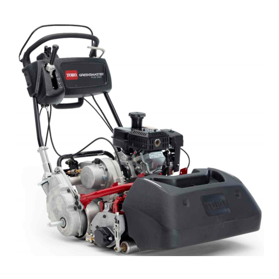
Toro Greensmaster Flex 2120 Operator's Manual
Traction unit
Hide thumbs
Also See for Greensmaster Flex 2120:
- Service manual (198 pages) ,
- Operator's manual (41 pages) ,
- Instructions manual (16 pages)

Related Manuals for Toro Greensmaster Flex 2120


Summary of Contents for Toro Greensmaster Flex 2120
- Page 1 Form No. 3435-609 Rev A Greensmaster ® Flex ™ 2120 Traction Unit Model No. 04053—Serial No. 400000000 and Up *3435-609* A Register at www.Toro.com. Original Instructions (EN)
- Page 2 This product complies with all relevant European Whenever you need service, genuine Toro parts, or directives; for details, please see the separate product additional information, contact an authorized Toro specific Declaration of Conformity (DOC) sheet. distributor and have the model and serial numbers of your product ready.
-
Page 3: Table Of Contents
Contents Cleaning the Fuel-Tank Screen......33 Electrical System Maintenance ......34 Servicing the Traction-Interlock Switch Safety ............... 4 ..............34 General Safety........... 4 Servicing the Brake-Interlock Switch....34 Safety and Instructional Decals ......4 Brake Maintenance ..........35 Setup ................ 7 Adjusting the Service/Parking Brake.... -
Page 4: Safety
Safety • Do not operate the machine without all guards and other safety protective devices in place and functioning properly on the machine. This machine has been designed in accordance with • Keep bystanders and children out of the operating EN ISO 5395 and ANSI B71.4-2017 and meets these area. - Page 5 decal120-9571 120-9571 1. Lower the lever to disengage the traction. decal131-3111 131-3111 1. Fast 2. Slow decal120-9598 120-9598 1. Brake 4. Parking brake decal133-8062 2. Release handle to 5. Rotate the latch to lock the 133-8062 disengage the brake. parking brake; compress the handle to release the latch.
- Page 6 decal115-7274 115-7274 1. Lights (optional) 3. Engine—start 2. Hour meter 4. Engine—shut off decal133-2335 133-2335 1. Warning—read the Operator’s Manual; 3. Thrown object hazard—keep 5. Do not tow the machine. all operators should be trained before bystanders away. operating the machine. 2.
-
Page 7: Setup
Setup Loose Parts Use the chart below to verify that all parts have been shipped. Procedure Description Qty. – No parts required Prepare the traction unit (optional). Bolt (3/8 x 3/4 inch) Install the cutting unit to the traction unit. Handle retainer Install the handle retainers. -
Page 8: Preparing The Traction Unit
Preparing the Traction Unit Installing the Cutting Unit to the Traction Unit Optional—Cutting Unit Models 04251, 04252, 04253, or 04254 Parts needed for this procedure: Bolt (3/8 x 3/4 inch) No Parts Required Procedure Procedure Note: To install the weight rod onto your machine, If you are installing cutting unit Model No. -
Page 9: Installing The Handle Retainers
Installing the Handle Retainers Parts needed for this procedure: Handle retainer Hairpin cotter g000483 Figure 6 1. Transmission coupling Procedure While supporting the handle, remove the cable Maneuver the machine frame forward until it ties that secure the handle clamps to the side engages the cutting unit pivot arms Figure plates... -
Page 10: Installing The Transport Wheels
Installing the Transport Wheels Optional Parts needed for this procedure: Transport wheels—Transport Wheel Kit (Model No. 04123 [Optional]) Procedure g017591 Use your foot to push the center of the kickstand Figure 10 down and pull up on the lower handle support 1. -
Page 11: Installing The Production-Year Decal
Installing the Production-Year Decal CE Machines Only Parts needed for this procedure: g032407 Production-year decal Figure 12 1. Basket hooks Procedure Install the basket hooks over the frame loop If you use this machine in a country that complies to (Figure 12). -
Page 12: Breaking In The Machine
Product Overview Breaking in the Machine No Parts Required Procedure Only 8 hours of mowing operation is required for the break-in period. The first several hours of operation are critical to future dependability of the machine. You must monitor the machine performance closely so that minor difficulties, which could lead to major problems, are noted and can be corrected. - Page 13 Throttle Control The throttle control (Figure 15 Figure 16) is located on the right, rear side of the control panel. Rotate the throttle to regulate the engine speed. g027738 Figure 16 g000494 Figure 17 1. Full speed 2. Slow speed 1.
- Page 14 Service Brake Choke Lever The service brake (Figure 18) is located on the left The choke lever (Figure 19) is located on the left front front side of the handle. Pulling back the lever applies of the engine. Use the lever to aid in starting a cold the service brake.
- Page 15 Recoil-Starter Handle Pull the recoil-starter handle (Figure 19) to start the engine. Kickstand The kickstand (Figure 21) is mounted to the rear of the machine. Use the kickstand when you install or remove the transport wheels or the cutting unit. •...
-
Page 16: Specifications
Authorized Service Dealer or authorized Toro • Know how to stop the machine and shut off the distributor or go to www.Toro.com for a list of all machine quickly. approved attachments and accessories. •... -
Page 17: Performing Daily Maintenance
Filling the Fuel Tank such equipment with a portable container rather than from a fuel-dispenser nozzle. • Keep the nozzle in contact with the rim of the fuel DANGER tank or container operating at all times until fueling In certain conditions, fuel is extremely is complete. - Page 18 WARNING Fuel is harmful or fatal if swallowed. Long-term exposure to vapors can cause serious injury and illness. • Avoid prolonged breathing of vapors. • Keep your face away from the nozzle and fuel tank or conditioner bottle opening. • Avoid contact with skin; wash off spills with soap and water.
-
Page 19: Setting The Machine To Match Turf Conditions
Setting the Machine to Match Turf Conditions Use the following table to set the machine to match turf conditions. Bedbars: Standard and Optional (Flex/eFlex 2120 Machines) Part Number Description Aggressiveness Comments 106-2468-01 Non-Aggressive Less Red, Standard 99-3794-03 Aggressive More Black Bedbars: Standard and Optional (Flex/eFlex 1820 Machines) 110-2282-01 Non-Aggressive... -
Page 20: Adjusting The Handle Height
Adjusting the Handle Height Note: The machine is shipped with the handle adjusted to the lowest position. The machine is normally operated with the handle telescoped out to its maximum height. Loosen the 3 carriage bolts and nuts securing each side of the handle in the handle clamps (Figure 24). -
Page 21: Checking The Operation Of The Interlock Switches
Checking the Operation of traction lever should disengage. If the traction lever does not disengage, the interlock system the Interlock Switches needs service. Correct the problem before operating the machine; refer to Servicing the Service Interval: Before each use or daily Traction-Interlock Switch (page 34). -
Page 22: Transporting The Machine To A Job Site
With the engine running, engage the service Securely fasten the machine to the trailer. brake (not the parking-brake latch), press the Note: You can use the Toro Trans Pro trailer to OPC, and engage the traction lever (Figure 27). transport the machine. For instructions on loading the The engine should labor to overcome the brake trailer, refer to your trailer Operator’s Manual. -
Page 23: During Operation
• Use only accessories and attachments approved • Before you start the machine, ensure that all drives by The Toro® Company. are in neutral, the parking brake is engaged, and you are in the operating position. Slope Safety •... -
Page 24: Starting The Engine
Note: – Evaluate the site conditions of the day to The choke may not be required when determine if the slope is safe for machine starting a warm engine. operation. Use common sense and good Pull the recoil-start handle out until positive judgment when performing this evaluation. -
Page 25: Operating Tips
Light Conditions spring loaded lever. Use the LED Light Kit when you operate the machine Move the machine as needed in low light conditions; contact your authorized Toro Important: If possible, do not tow the distributor. machine. If it is absolutely necessary, do... -
Page 26: After Operation
Move the lever to the traction—F ORWARD and reel drive—E position (Figure 32), NGAGE increase the throttle speed until the machine is traveling at the desired ground speed, drive the machine onto the green, lower the cutting unit to the ground, and begin mowing. Operating the Controls after Mowing Drive off the green, move the reel drive and... -
Page 27: Maintenance
Download a free copy of the electrical or Keep bystanders away. hydraulic schematic by visiting www.Toro.com and searching for your machine from the Manuals link on • Clean grass and debris from the cutting unit, drive, the home page. -
Page 28: Recommended Maintenance Schedule(S)
• Replace the paper filter element (More frequently in dusty operating conditions). Every 300 hours • Replace the spark plug. • Replace the clutch oil with ATF D/M Automatic Transmission Fluid (Toro Part No. Every 500 hours 505-136). • Inspect the reel-drive belt. -
Page 29: Daily Maintenance Checklist
Daily Maintenance Checklist Important: Duplicate this page for routine use. Maintenance For the week of: Check Item Mon. Tues. Wed. Thurs. Fri. Sat. Sun. Check the safety interlock operation. Check the parking brake operation. Check that pivot joints operate freely. Check the fuel level. -
Page 30: Pre-Maintenance Procedures
Pre-Maintenance Engine Maintenance Procedures Engine Safety • Preparing the Machine for Do not change the governor speed or overspeed the engine. Maintenance • Run the engine dry or remove the fuel with a hand pump; never siphon the fuel. If you must drain the fuel tank, do it outdoors. - Page 31 Changing the Engine Oil Service Interval: After the first 20 hours/After the first month (whichever comes first) Every 100 hours/Every 6 months (whichever comes first) WARNING Oil may be hot after the engine has been run, and contact with hot oil can cause severe personal injury.
-
Page 32: Servicing The Air Cleaner
Servicing the Air Cleaner Service Interval: Before each use or daily Every 50 hours/Every 3 months (whichever comes first) Every 300 hours/Yearly (whichever comes first) Important: Do not operate the engine without the air filter assembly; extreme engine damage will occur. Shut off the engine and wait for all moving parts to stop;... -
Page 33: Servicing The Spark Plug
Servicing the Spark Plug Fuel System Maintenance Service Interval: Every 100 hours/Every 6 months (whichever comes first) Every 300 hours/Yearly (whichever comes first) Cleaning the Fuel-Tank Use an NGK BPR6ES spark plug or equivalent. Screen Shut off the engine and wait for all moving parts to stop;... -
Page 34: Electrical System Maintenance
Servicing the Electrical System Brake-Interlock Switch Maintenance Ensure that the engine is off. Servicing the Remove the control panel. Engage the service-brake lever and engage the Traction-Interlock Switch parking-brake latch. Use the following procedure if the traction-interlock Loosen and remove the interlock-switch switch needs adjustment or replacement. -
Page 35: Brake Maintenance
Brake Maintenance Belt Maintenance Adjusting the Inspecting the Reel-Drive Service/Parking Brake Belt If the service/parking brake slips when operated, Service Interval: Every 1,000 hours adjust the cable as follows: Shut off the engine and remove the key. Move the service/parking brake lever to the O Loosen the flange bolt that secures the belt position. -
Page 36: Visually Inspecting The Reel Clutch
Engaging/Disengaging Clean any debris from inside the belt compartment and from around the the Transmission-Belt compression spring (Figure 44). Ensure that the compression spring is Tensioner applying the proper tension on the belt. The transmission belt is tensioned by a spring-loaded Tighten the bearing housing mounting nut. -
Page 37: Controls System Maintenance
(Figure 48); if Transmission Fluid (Toro Part No. 505-136) it is not within 7.3 to 7.6 cm (2-7/8 to 3 inches), Remove the vent from the breather from the adjust the clutch according to the steps below. -
Page 38: Adjusting The Reel Control
Repair or replace any part that is worn or damaged. Paint all scratched or bare metal surfaces. Paint is available from your authorized Toro distributor. Store the machine on a level surface in a clean, dry garage or storage area. Cover the machine... - Page 39 Notes:...
- Page 40 Notes:...
- Page 41 Notes:...
- Page 42 The Toro Company (“Toro”) respects your privacy. When you purchase our products, we may collect certain personal information about you, either directly from you or through your local Toro company or dealer. Toro uses this information to fulfil contractual obligations - such as to register your warranty, process your warranty claim or to contact you in the event of a product recall - and for legitimate business purposes - such as to gauge customer satisfaction, improve our products or provide you with product information which may be of interest.
- Page 43 While the exposure from Toro products may be negligible or well within the “no significant risk” range, out of an abundance of caution, Toro has elected to provide the Prop 65 warnings. Moreover, if Toro does not provide these warnings, it could be sued by the State of California or by private parties seeking to enforce Prop 65 and subject to substantial penalties.
- Page 44 Countries Other than the United States or Canada Customers who have purchased Toro products exported from the United States or Canada should contact their Toro Distributor (Dealer) to obtain guarantee policies for your country, province, or state. If for any reason you are dissatisfied with your Distributor's service or have difficulty obtaining guarantee information, contact your Authorized Toro Service Center.