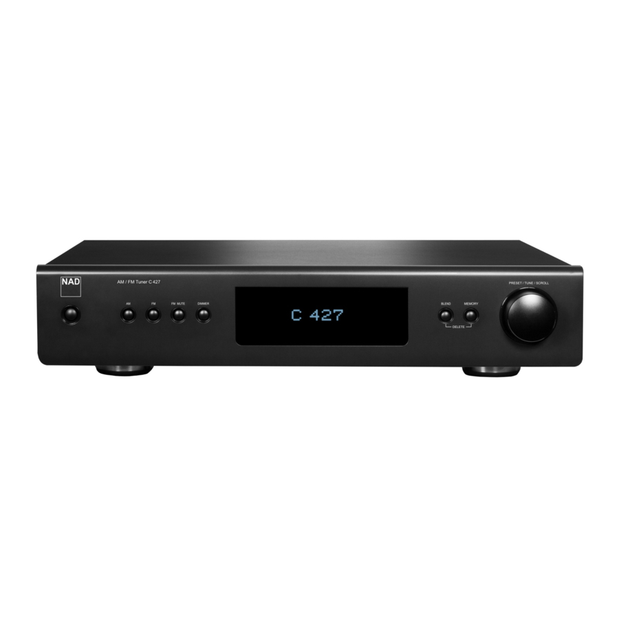
NAD C427 - AM/FM Tuner Manual
- Service manual (23 pages) ,
- Owner's manual (12 pages) ,
- Quick setup manual (2 pages)
Advertisement
IMPORTANT SAFETY INSTRUCTIONS
SAVE THESE INSTRUCTIONS FOR LATER USE.
FOLLOW ALL WARNINGS AND INSTRUCTIONS MARKED ON THE AUDIO EQUIPMENT.
- Read instructions - All the safety and operating instructions should be read before the product is operated.
- Retain instructions - The safety and operating instructions should be retained for future reference.
- Heed Warnings - All warnings on the product and in the operating instructions should be adhered to.
- Follow Instructions - All operating and use instructions should be followed.
- Cleaning - Unplug this product from the wall outlet before cleaning. Do not use liquid cleaners or aerosol cleaners. Clean only with a dry cloth.
- Attachments - Do not use attachments not recommended by the product manufacturer as they may cause hazards.
- Water and Moisture - Do not use this product near water-for example, near a bath tub, wash bowl, kitchen sink, or laundry tub; in a wet basement; or near a swimming pool; and the like.
- Accessories - Do not place this product on an unstable cart, stand, tripod, bracket, or table. The product may fall, causing serious injury to a child or adult, and serious damage to the product. Use only with a cart, stand, tripod, bracket, or table recommended by the manufacturer, or sold with the product. Any mounting of the product should follow the manufacturer's instructions, and should use a mounting accessory recommended by the manufacturer.
![]()
A product and cart combination should be moved with care. Quick stops, excessive force, and uneven surfaces may cause the product and cart combination to overturn.- Ventilation - Slots and openings in the cabinet are provided for ventilation and to ensure reliable operation of the product and to protect it from overheating, and these openings must not be blocked or covered. The openings should never be blocked by placing the product on a bed, sofa, rug, or other similar surface. This product should not be placed in a built-in installation such as a bookcase or rack unless proper ventilation is provided or the manufacturer's instructions have been adhered to.
- Power Sources - This product should be operated only from the type of power source indicated on the marking label. If you are not sure of the type of power supply to your home, consult your product dealer or local power company. The primary method of isolating the amplifier from the mains supply is to disconnect the mains plug. Ensure that the mains plug remains accessible at all times. Unplug the AC power cord from the AC outlet if the unit will not be used for several months or more.
- Grounding or Polarization - This product may be equipped with a polarized alternating current line plug (a plug having one blade wider than the other). This plug will fit into the power outlet only one way. This is a safety feature. If you are unable to insert the plug fully into the outlet, try reversing the plug. If the plug should still fail to fit, contact your electrician to replace your obsolete outlet. Do not defeat the safety purpose of the polarized plug.
- Power Cord Protection - Power supply cords should be routed so that they are not likely to be walked on or pinched by items placed upon or against them, paying particular attention to cords at plugs, convenience receptacles, and the point where they exit from the product.
- Outdoor Antenna Grounding - If an outside antenna or cable system is connected to the product, be sure the antenna or cable system is grounded so as to provide some protection against voltage surges and built-up static charges. Article 810 of the National Electrical Code, ANSI/NFPA 70, provides information with regard to proper grounding of the mast and supporting structure, grounding of the lead-in wire to an antenna discharge unit, size of grounding conductors, location of antenna discharge unit, connection to grounding electrodes, and requirements for the grounding electrode.

NOTE TO CATV SYSTEM INSTALLER
This reminder is provided to call the CATV system installer's attention to Section 820-40 of the NEC which provides guidelines for proper grounding and, in particular, specifies that the cable ground shall be connected to the grounding system of the building, as close to the point of cable entry as practical.

OPTIONAL ANTENNA GROUNDING ELECTRODE.
DRIVEN 8 FEET (2.44M) INTO THE EARTH IF REQUIRED BY LOCAL CODES, SEE NEC SECTION 810.21(f).
- Lightning - For added protection for this product during a lightning storm, or when it is left unattended and unused for long periods of time, unplug it from the wall outlet and disconnect the antenna or cable system. This will prevent damage to the product due to lightning and power line surges.
- Power Lines - An outside antenna system should not be located in the vicinity of overhead power lines or other electric light or power circuits, or where it can fall into such power lines or circuits. When installing an outside antenna system, extreme care should be taken to keep from touching such power lines or circuits as contact with them might be fatal.
![burn hazard]()
![shock hazard]()
Overloading - Do not overload wall outlets, extension cords, or integral convenience receptacles as this can result in a risk of fire or electric shock.![burn hazard]()
![shock hazard]()
Object and Liquid Entry - Never push objects of any kind into this product through openings as they may touch dangerous voltage points or short-out parts that could result in a fire or electric shock. Never spill liquid of any kind on the product.

THE APPARATUS SHOULD NOT BE EXPOSED TO DRIPPING OR SPLASHING, AND OBJECTS FILLED WITH LIQUIDS, SUCH AS VASES, SHOULD NOT BE PLACED ON THE APPARATUS. AS WITH ANY ELECTRONIC PRODUCTS, USE CARE NOT TO SPILL LIQUIDS INTO ANY PART OF THE SYSTEM. LIQUIDS CAN CAUSE A FAILURE AND/OR A FIRE HAZARD.
- Damage Requiring Service - Unplug this product from the wall outlet and refer servicing to qualified service personnel under the following conditions:
- When the power supply cord or plug is damaged.
- If liquid has been spilled, or objects have fallen into the product.
- If the product has been exposed to rain or water.
- If the product does not operate normally by following the operating instructions. Adjust only those controls that are covered by the operating instructions as an improper adjustment of other controls may result in damage and will often require extensive work by a qualified technician to restore the product to its normal operation.
- If the product has been dropped or damaged in any way.
- when the product exhibits a distinct change in performance-this indicates a need for service.
![burn hazard]()
![shock hazard]()
Replacement Parts - When replacement parts are required, be sure the service technician has used replacement parts specified by the manufacturer or have the same characteristics as the original part. Unauthorized substitutions may result in fire, electric shock, or other hazards.- Safety Check - Upon completion of any service or repairs to this product, ask the service technician to perform safety checks to determine that the product is in proper operating condition.
- Wall or Ceiling Mounting - The product should be mounted to a wall or ceiling only as recommended by the manufacturer.
- Heat - The product should be situated away from heat sources such as radiators, heat registers, stoves or other products (including amplifiers) that produce heat.
- Headphones - Excessive sound pressure form earphones and headphones can cause hearing loss.
![burn hazard]() Battery Disposal - When disposing of used batteries, please comply with governmental regulations or environmental public instruction's rules that apply in your country or area. Batteries (battery pack or batteries installed) must not be exposed to excessive heat such as sunshine, fire or the like.
Battery Disposal - When disposing of used batteries, please comply with governmental regulations or environmental public instruction's rules that apply in your country or area. Batteries (battery pack or batteries installed) must not be exposed to excessive heat such as sunshine, fire or the like.

Danger of explosion if battery is incorrectly replaced. Replace only with the same or equivalent type.


TO REDUCE THE RISK OF FIRE OR ELECTRIC SHOCK, DO NOT EXPOSE THIS PRODUCT TO RAIN OR MOISTURE.

TO PREVENT ELECTRIC SHOCK, MATCH WIDE BLADE OF PLUG TO WIDE SLOT, FULLY INSERT.
 THE LIGHTNING FLASH WITH ARROWHEAD SYMBOL, WITHIN AN EQUILATERAL TRIANGLE, IS INTENDED TO ALERT THE USER TO THE PRESENCE OF UNINSULATED "DANGEROUS VOLTAGE" WITHIN THE PRODUCT'S ENCLOSURE THAT MAYBE OF SUFFICIENT MAGNITUDE TO CONSTITUTE A RISK OF ELECTRIC SHOCK TO PERSONS.
 THE EXCLAMATION POINT WITHIN AN EQUILATERAL TRIANGLE IS INTENDED TO ALERT THE USER TO THE PRESENCE OF IMPORTANT OPERATING AND MAINTENANCE (SERVICING) INSTRUCTIONS IN THE LITERATURE ACCOMPANYING THE APPLIANCE.
RISK OF ELECTRIC SHOCK
DO NOT OPEN
TO REDUCE THE RISK OF ELECTRIC SHOCK, DO NOT REMOVE COVER (OR BACK), NO USER-SERVICEABLE PARTS INSIDE REFER SERVICING TO QUALIFIED SERVICE PERSONNEL.
THE EQUIPMENT MUST BE CONNECTED TO AN EARTHED MAINS SOCKET-OUTLET.
The mains plug of the apparatus should be easily accessible or free from any obstruction during intended use.
Changes or modifications to this equipment not expressly approved by NAD Electronics for compliance could void the user's authority to operate this equipment.
CAUTION REGARDING PLACEMENT
To maintain proper ventilation, be sure to leave a space around the unit (from the largest outer dimensions including projections) that is equal to or greater than shown below.
Left and Right Panels: 10 cm
Rear Panel: 10 cm
Top Panel: 50 cm
NOTES ON ENVIRONMENTAL PROTECTION

At the end of its useful life, this product must not be disposed of with regular household waste but must be returned to a collection point for the recycling of electrical and electronic equipment. The symbol on the product, user's manual and packaging, point this out.
The materials can be reused in accordance with their markings. Through re-use, recycling of raw materials or other forms of recycling of old products, you are making an important contribution to the protection of our environment. Your local administrative office can advise you of the responsible waste disposal point.
RECORD YOUR MODEL NUMBER (NOW, WHILE YOU CAN SEE IT)
The model and serial number of your new C 427 are located on the back of the cabinet. For your future convenience, we suggest that you record these numbers here:
INTRODUCTION
One more thing: We urge you to register your C 427 ownership on the NAD Worldwide Web site:
http://NADelectronics.com/salon
For warranty information contact your local distributor.
WHAT'S IN THE BOX
Packed with your C 427 you will find
- An AM loop antenna
- A FM ribbon-wire antenna with balun
- A detachable AC power cord
- An audio cable connector (RCA-to-RCA lead)
- The TNR 3 remote control with 2 (two) AAA batteries
- Quick Setup Guide
SAVE THE PACKAGING
Please save the box and all of the packaging in which your C 427 arrived. Should you move or otherwise need to transport your C 427, this is by far the safest container in which to do so. We've seen too many otherwise perfect components damaged in transit for lack of a proper shipping carton, so please: Save that box!
CHOOSING A LOCATION
Choose a location that is well ventilated (with at least several inches to both sides and behind), and that will provide a clear line of sight, within 23 feet/7 meters, between the C 427's front panel and your primary listening/viewing position—this will ensure reliable infrared remote control communications.
Avoid placing the unit in direct sunlight or near sources of heat and damp. It is perfectly possible to stack the C 427 on top of other components.
QUICK START
In case you simply cannot wait to experience the performance of your new C 427, we provide the following "Quick Start" instructions to get you underway.
Please make all the connections to your C 427 with the unit unplugged. It is also advisable to power down or unplug all associated components while making or breaking any signal or AC power connections.
- Use the RCA-to-RCA lead to connect the left and right audio output of the C 427 to the tuner input of your amplifier.
- Connect AM and FM antenna.
- Connect corresponding end of the AC power cord to the AC mains input of the C 427 and the plug connected to a mains power source. The Standby LED indicator embedded around the bezel of the STANDBY button will illuminate amber.
- Plug the AC mains plug also of your amplifier to a mains power source. Power up your amplifier and set it to the tuner input where the C 427 is connected.
- Press the front panel STANDBY button to turn ON the C 427. The Standby LED indicator will turn from amber to blue and the VFD is illuminated.
- Select AM or FM band by pressing corresponding front panel button.
- Toggle [PRESET/TUNE/SCROLL] control knob to switch between "Presets" and "Tune" mode. Select TUNE mode ("Tune" is displayed in the second row of the VFD).
- Tune to desired station by rotating the [PRESET/TUNE/SCROLL] control knob.
IDENTIFICATION OF CONTROLS
FRONT PANEL

- STANDBY BUTTON
- Press this button to switch ON the C 427 from standby mode. The Standby LED indicator will turn from amber to blue and illuminate the VFD.
- Pressing the STANDBY button again turns the unit back to standby mode.
- STANDBY LED
- This indicator will light up amber when the C 427 is at standby mode.
- When the C 427 is powered up from standby mode, this indicator will illuminate blue.
NOTE
In order to turn ON the C 427 from standby mode or back to standby mode, the rear panel POWER switch must be in the ON position.
- AM
- Select AM band.
- FM
- Select FM band.
- FM MUTE
- The front panel [FM MUTE] button is a dual-purpose control. In the normal position, "Stereo" and "FM Mute" are shown in the VFD; only the stations with a strong signal can be listened to, and the noise between stations is muted.
- Pressing the [FM MUTE] button again ("Stereo" and "FM Mute" are extinguished; "Tuned" is displayed) allows distant and potentially noisy stations to be received. Noise is reduced if the FM station signal level is less than the FM Stereo threshold (since mono FM is inherently less noise-prone) though at the sacrifice of the stereo effect.
- The "FM MUTE" status can be stored for individual presets.
- DIMMER
- Toggle the [DIMMER] button to reduce or restore VFD brightness.
- REMOTE SENSOR
- Point the TNR 3 remote control at the remote sensor and press the buttons. Do not expose the remote sensor of the C 427 to a strong light source such as direct sunlight or illumination. If you do so, you may not be able to operate C 427 with the remote control.
Distance: About 23 ft (7 m) from the front of the remote sensor
Angle: About 30° in each direction of the front of the remote sensor
- VACUUM FLUORESCENT DISPLAY (VFD)
- Provide visual information on the settings, conditions, status and other information relevant to the currently tuned station.
- BLEND
- The NAD BLEND feature will allow you to reduce the amount of noise and hiss but still retain some level of stereo separation, instead of mono.
- The [BLEND] button toggles between engaging and disengaging the BLEND feature. When activated, "Blend On" is shown in the VFD; "Blend Off" when not activated.
- The "BLEND" status can be stored for individual presets.
- In combination with [MEMORY] button, [BLEND] button is also used in deleting stored presets. Refer also to the item about DELETE A PRESET at the LISTENING TO AM/FM RADIO section of the OPERATION page.
- MEMORY
- Press this button to store tuned AM or FM stations to the C 427's 40 preset-memory locations. One can store a mix of any AM or FM stations to the 40 available presets.
- In combination with [BLEND] button, [MEMORY] button is also used in deleting stored presets. Refer also to the item about DELETE A PRESET at the LISTENING TO AM/FM RADIO section of the OPERATION page.
- PRESET/TUNE/SCROLL CONTROL KNOB
- Toggle to switch between "Presets" and "Tune" mode. "Tune" or "Presets" will be displayed in the second line of the VFD depending upon the mode selected.
Preset mode: Rotate the PRESET/TUNE/SCROLL control knob to the left to scroll to a lower Preset number; rotate the PRESET/TUNE/SCROLL control knob to the right to scroll to a higher Preset number. This is a "wrap-around" function – upon reaching the last stored Preset number, preset search will continue on with the first stored Preset number and vice-versa. Unused preset numbers are skipped over.
Tune mode: Rotate the PRESET/TUNE/SCROLL control knob for precise tuning to a specific frequency. With each brief rotation, the tuner will take 0.05 MHz steps at FM band and 10 kHz (120V version) or 9 kHz (230V version) at AM band. When tuned accurately to a station, "Tuned" is displayed in the VFD.
REAR PANEL

ATTENTION!
Please make sure that the C 427 is powered off or unplugged before making any connections. It is also advisable to power down or unplug all associated components while making or breaking any signal or AC power connections.
- FM ANTENNA TERMINAL
- Connect the supplied lead-type FM antenna to the FM antenna input. Extend the lead. Experiment freely with your antenna placement and orientation until you get the clearest sound and lowest background noise. Fix the antenna in the desired position by using thumb tacks, push pins or any suitable means.
AM ANTENNA TERMINAL
- The AM loop antenna supplied with the C 427 (or a suitable replacement) is required for AM reception. Open the clip terminal lever; insert the wire making sure to match the color-coded (white and black) ends of the wire to that of the terminal and close the lever ensuring that the lever locks the wire in place.
- Testing different positions for the antenna may improve reception; vertical orientation will usually produce the best results. Antenna proximity to large metal objects (appliances, radiators) may impair reception, as will attempts to lengthen the wire to the loop.
- If an external AM antenna is used, make connections to the AM and GND terminals in accordance with the instructions supplied with the antenna. Refer also to the item about ASSEMBLING THE LOOP ANTENNA at the LISTENING TO AM/FM RADIO section of the OPERATION page.
- AUDIO OUT (L, R)
- Connect to the corresponding analog audio input of an amplifier, receiver or stereo system.
- RS-232
- Connect this interface using RS-232 serial cable (not supplied) to any Windows compatible PC to allow remote control of the C 427 via compatible external controllers.
- NAD is a certified partner of AMX and Crestron and fully supports these external devices. Check out the NAD website for information about AMX and Crestron compatibility with NAD. See your NAD audio specialist for more information.
- Refer to the NAD website for information about RS232 Protocol documents and PC interface program.
- IR IN
- This input is connected to the output of an IR (infrared) repeater (Xantech or similar) or the IR output of another component to allow control of the C 427 from a remote location.
- Most NAD products with IR OUT are fully compatible with the C 427.
- +12V TRIGGER IN
- This input allows the C 427 to be switched remotely to standby mode and ON by ancillary equipment, such as an amplifier, preamp, AV processor, etc. The controlling device must be equipped with a 12V trigger output to use this feature.
- Connect this +12V trigger input to the remote component's corresponding +12V DC output jack using a mono cable with 3.5mm male plug.
- POWER
- Supply the AC mains power to the C 427.
- When the POWER switch is set to ON position, the C 427 goes to standby mode as shown by the amber status condition of the Standby LED. Press the front panel Standby button or remote control's [ON] button to switch ON the C 427 from standby mode.
- If you intend not to use the C 427 for long periods of time (such as when on vacation), switch off the POWER switch.
- With POWER switched off, neither the front panel Standby button nor remote control's [ON] button can activate the C 427.
- AC MAINS INPUT
- The C 427 comes supplied with a separate detachable AC power cord. Connect corresponding end of the AC power cord to the AC mains input of the C 427 and the plug connected to a mains power source.
- Connect only to the prescribed mains power source, i.e., 120V 60 Hz (for 120V version models of C 427 only) or 230V 50 Hz (for 230V version models of C 427 only).
- Always disconnect the plug from the mains power source first, before disconnecting the other end of the AC power cord from the C 427's AC Mains input socket.
- If you intend not to use the C 427 for long periods of time, disconnect the plug from the mains power source.
TNR 3 REMOTE CONTROL

- ON: Power up C 427 from standby mode.
- OFF: Switch C 427 to standby mode.
- 0-9 number buttons: Direct-entry of frequency channel or Preset number.
- SLEEP: Set sleep mode timer.
- MEM: Save current station to a Preset number.
- DEL: Delete selected Preset number.
- PRESET: Step up or down between Presets.
TUNE: Tune forward or backwards.
ENTER: Select Tune or Presets mode. - AM:Select AM band.
- FM: Select FM band.
- BLEND: Activate or deactivate BLEND feature.
- FM MUTE: Activate or deactivate FM MUTE mode.
- DIMMER: Reduce or restore VFD brightness.
OPERATION
SLEEP MODE
The Sleep Mode timer will switch the C 427 to standby mode automatically after a preset number of minutes. Toggle TNR 3's [SLEEP] key to select through the following Sleep mode timer settings - Sleep 15 Min, Sleep 30 Min, Sleep 45 Min, Sleep 60 Min, Sleep 75 Min, Sleep 90 Min and Sleep Off. Stop at the desired Sleep mode timer setting.
When the timer is set, "Sleep xx Min" is displayed in VFD where "xx" stands for the number of minutes remaining before the C 427 goes to standby mode.
To cancel the sleep mode, continue pressing the TNR 3's [SLEEP] button until "Sleep Off" is displayed on the VFD. Switching the C 427 to standby mode from either the TNR 3's [OFF] button or the front panel Standby button will also cancel the sleep mode.
The C 427 offers very high quality sound from radio broadcasts. The reception and sound quality will always be dependent to a degree however on the type of antenna(s) used as well as proximity to the broadcast origin, geography and weather conditions.
ABOUT ANTENNAS
Connect the supplied lead-type FM antenna to the FM antenna input. Extend the lead. Experiment freely with your antenna placement and orientation until you get the clearest sound and lowest background noise. Fix the antenna in the desired position by using thumb tacks, push pins or any suitable means.
In areas of poor FM reception, an exterior FM antenna can improve performance dramatically. If radio listening is important to you, consider consulting an antenna installation professional to optimize your system.
The supplied AM "loop" antenna will usually provide adequate reception.
However, an exterior AM antenna can be used to improve reception. Consult an antenna professional for more information.
ASSEMBLING THE LOOP ANTENNA
- Rotate the outer frame of the antenna.
![]()
- Insert the bottom edge of the outer frame into the groove on the stand.
![]()
- Extend the antenna cord.
![]()


SELECTING A TUNER BAND
Select AM or FM band by pressing corresponding front panel button. Using the TNR 3, select desired band by directly pressing [AM] or [FM] button.
TUNING STATIONS
Toggle front panel's [PRESET/TUNE/SCROLL] control knob to switch between "Presets" and "Tune" mode. Select "Tune" or "Presets". "Tune" or "Presets" will be displayed in the second line of the VFD depending upon the mode selected. Rotate [PRESET/TUNE/SCROLL] control knob for precise tuning to a specific frequency or to select desired Preset number.
DIRECT TUNING
If you know your desired station's frequency allocation, you can tune directly to the station.
- Toggle [ENTER] button of the remote control to switch between "Presets" and "Tune" mode. Select TUNE mode.
- Using the numeric keys of the remote control, key-in the frequency allocation of the station. For example, to enter 104.50MHz, press "1", "0", "4", "5" and "0" or press "1", "0", "4" and "5".
STORING PRESETS
The C 427 can store a mix of your 40 favorite AM and FM stations for immediate recall.
- To store a desired AM/FM station to a preset, first tune to the desired frequency, then press the front panel's [MEMORY] button. The VFD will show the next available Preset number - for example, "Preset 04 Free".
- Press [MEMORY] button again to store the desired frequency on the Preset number shown ("P04" is shown in the upper right corner of the VFD). Your desired frequency is now stored in the assigned preset number.
DIRECT RECALL OF A PRESET
You can directly recall a desired Preset number.
- Toggle front panel's [PRESET/TUNE/SCROLL] control knob to switch between "Presets" and "Tune" mode. Select "Presets" mode.
- Using the numeric keys of the remote control, key-in directly your desired Preset number.
DELETE A PRESET
Selected Preset (for example, "P04") can be deleted using either of the following methods.
Using front panel buttons
- Press and hold front panel button's [BLEND] and then [MEMORY] to delete selected Preset – "P04" transforms to "P--".
Using TNR 3
- Press and hold TNR 3's [DEL] button until "P04" transforms to "P--".
ABOUT RDS
The Radio Data System (RDS) permits sending small amounts of digital information using conventional FM radio broadcasts. The C 427 supports two RDS modes, program-service name (PS mode) and radio-text (RT mode). Not every FM station incorporates RDS in its broadcast signal. In most areas you will find from one to several RDS-enabled stations, but it is by no means impossible that your favorite stations will not be broadcasting RDS data.
When an RDS-enabled FM broadcast is tuned, the VFD will show its program-service name (PS) text and the station's radio-text (RT) readout, if any, which might scroll song- or artist-name, or any other text of the station's choosing.
TROUBLESHOOTING
| CONDITION | POSSIBLE CAUSES | POSSIBLE SOLUTIONS |
No power |
|
|
No sound |
|
|
|
| |
Noisy reception, hiss |
|
|
Reception with whistling, buzzing noise |
|
|
No RDS information |
|
|
|
| |
| C 427 does not respond to remote control commands. |
|
|
|
| |
|
|
RESTORING THE DEVICE TO ITS FACTORY DEFAULT SETTINGS
For AH version units
- Press and hold both the front panel [FM] and [MEMORY] buttons until the VFD shows
AH Reset...
complete
For C version units
- Press and hold both the front panel [FM] and [BLEND] buttons until the VFD shows
C Reset...
complete
The C 427 is now restored to its factory default settings with all Presets cleared.
SPECIFICATIONS
| FM SECTION | |
| Usable Sensitivity (98 MHz) | 10 dBμ |
| Signal/Noise Ratio | 65 dB (60 dBμ IHF-WTD Mono) 60 dB (60 dBμ IHF-WTD Stereo) |
| Frequency Response | ±1.5 dB (20 Hz - 15 kHz, 60 dBμ) |
| Channel Separation (60 dBμ) | 30 Hz: 33 dB 1 kHz: 40 dB 10 kHz: 32 dB |
| Capture Ratio (40 dBμ) | 3 dB |
| AM Suppression | 50 dB (60 dBμ, 100% Mod. FM, 30% Mod. AM) |
| Image Rejection (119.4 MHz) | 70 dB |
| I.F. Rejection (10.7 MHz) | 70 dB |
| Pilot Suppression (60 dBμ) | 60 dB |
| Total Harmonic Distortion* | Mono : 0.4% Stereo : 0.8% |
| Auto Search Sensitivity | 24 dBμ |
| RDS Decode Sensitivity | 26 dBμ |
| AM SECTION | |
| Usable Sensitivity (999/1000 Hz) | 55 dBμ |
| Signal/Noise Ratio (5 mV in) | 42 dB |
| Total Harmonic Distortion (5 mV in) | 1.5% |
| IF Rejection (450 kHz) | 40 dB |
| Image Rejection (F+2xIF) | 28 dB |
| Selectivity | 20 dB |
| Loop Sensitivity (20dB S/N) | 999/1000 Hz: 66 dB 603/600 Hz: 66 dB 1404/1400 Hz: 66 dB |
| Frequency response (100 - 2.3 kHz, 5 mV) | ±6 dB |
| GENERAL PARAMETERS | |
| Standby power | <0.5W |
| Unit dimensions (W x H x D) | 435 X 99 X 315 mm 17 1/8 x 3 15/16 x 12 7/16 inches |
| Shipping weight | 5.4 kg (11.9 lbs) |
*: 60 dBμ, L=R 75 kHz for 120V version; 40 kHz Dev for 230V version
NAD SHALL NOT BE HELD LIABLE FOR ANY TECHNICAL OR USER INTERFACE DISCREPANCIES IN THIS MANUAL. THE C 427 OWNER'S MANUAL MAY BE SUBJECT TO CHANGE WITHOUT PRIOR NOTICE. CHECK OUT WWW.NADELECTRONICS.COM FOR THE LATEST VERSION OF THE C 427 OWNER'S MANUAL.
NAD is a trademark of NAD Electronics International, a division of Lenbrook Industries Limited
Copyright 2016, NAD Electronics International, a division of Lenbrook Industries Limited

Documents / Resources
References
Download manual
Here you can download full pdf version of manual, it may contain additional safety instructions, warranty information, FCC rules, etc.
Advertisement
Thank you! Your question has been received!


Need Assistance?
Do you have a question about the C427 that isn't answered in the manual? Leave your question here.