
Subscribe to Our Youtube Channel
Related Manuals for Soredex CRANEX Novus e


Summary of Contents for Soredex CRANEX Novus e
- Page 1 ENGLISH CRANEX™ Novus e Digital Panoramic X-ray Unit Installation and Set-up Manual 208668 rev. 6...
- Page 3 Digital Panoramic X-ray Unit Installation and Set-up Manual CRANEX™ Novus e Installation and Setup Manual Document code 208668 rev. 6 Original approved English language version Manufactured by SOREDEX, PaloDEx Group Oy Nahkelantie 160 FI-04300 Tuusula, FINLAND Tel. +358 (0)10 270 2000 www.soredex.com...
- Page 4 Therefore, this document should not be regarded as an infallible guide to current product specifi cations. Soredex maintains the right to make changes and alterations without prior notice.
-
Page 5: Table Of Contents
Contents 1. Introduction ..................1 1.1 About this manual ..................1 1.2 Associated documentation ............... 1 1.3 Warnings and precautions ............... 2 1.4 Unit description ..................3 1.5 Disposal of the transportation packaging ..........5 2. Pre-installation requirements ............6 2.1 The Unit .................... - Page 6 4. Checking the alignment and fi nishing the installation ..... 40 4.1 Checking the alignment of the beam and the CCD sensor ....40 4.2 Checking the image geometry (Ball (and Pin) Phantom test) ....42 4.3 Checking the positioning lights ............... 44 4.4 Quality Assurance test ................
-
Page 7: Introduction
1.2 Associated documentation The CRANEX Novus e Digital Panoramic X-ray Unit User manual. The CRANEX Novus e Digital Panoramic X-ray Unit Service manual (not supplied in the delivery). -
Page 8: Warnings And Precautions
• If the unit is to be used with a 3rd party imaging application software, not produced or supplied by Soredex, the 3rd party imaging software must comply with all applicable local laws and regulations on patient information software. This includes, for example, the Medical Device Directive 93/42/EEC and / or the FDA. -
Page 9: Unit Description
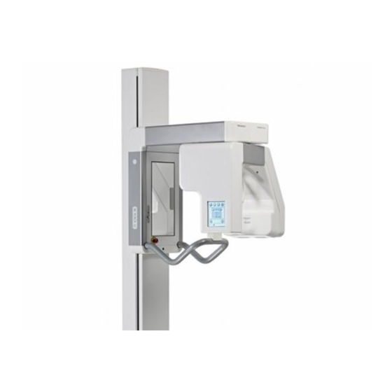
CRANEX Novus e 1. Introduction 1.4 Unit description Main parts Installation and set-up manual 208668... - Page 10 1. Introduction CRANEX Novus e Unit controls 1. Side control panel Lights key - switches the positioning lights on and off. Up / down keys Return key, drives rotating unit to the patient in/out position (PIO) 2. Main control panel...
-
Page 11: Disposal Of The Transportation Packaging
CRANEX Novus e 1. Introduction 1.5 Disposal of the transportation packaging The unit is transported in a corrugated cardboard box that is attached to a wooden pallet. Inside the box preformed expanded polystyrene packaging material protects the unit from shock and damage. -
Page 12: Pre-Installation Requirements
2. Pre-installation requirements CRANEX Novus e 2. Pre-installation requirements 2.1 The Unit • The unit is supplied in one box on a pallet. The dimensions of the box with pallet are:- Length Width Height 191 cm 85 cm 103 cm 76"... - Page 13 CRANEX Novus e 2. Pre-installation requirements • Make sure that the fi xing hardware to be used to attach the unit to the wall and the wall itself can withstand a continuous pull-out force of at least 300 kg (660 lb).
-
Page 14: The Pc
2. Pre-installation requirements CRANEX Novus e 2.2 The PC • The PC to be used with the unit must be installed in a location that meets all local and national safety requirements with regards the connection of a PC to an x-ray device. -
Page 15: Unit And Fi Xing Hole Dimensions
CRANEX Novus e 2. Pre-installation requirements 2.5 Unit and fi xing hole dimensions Installation and set-up manual 208668... -
Page 16: Fixing Hardware And Installation And Setup Tools
2. Pre-installation requirements CRANEX Novus e 2.6 Fixing hardware and installation and setup tools The following tools and hardware are required to install and set up the unit. NOTE: Fixing hardware and tools are NOT supplied with the unit. Fixing hardware for the unit WALL attachment requires: 10 mm (3/8") diameter fi... - Page 17 CRANEX Novus e 2. Pre-installation requirements Installation tools Electric drill Spanners (wrenches) 7, 10, 17 (two) mm AF Hexagon socket wrenches (Allen keys) 1.5 - 8 Slot blade screwdrivers 0.5 x 3 mm, 0.6 x 3.5 Torx screwdrivers T20, T25, T30...
-
Page 18: Installing The Unit
3. Installing the unit CRANEX Novus e 3. Installing the unit 3.1 Preparing the unit for installation 1. Transport the boxed unit to the location where the unit is to be installed. 2. Remove the straps that hold the box to the pallet. - Page 19 CRANEX Novus e 3. Installing the unit 4. Remove all the accessories, the accessory box and as much packaging material as possible. NOTE: DO NOT remove the packaging material that protects the upper shelf and the rotating unit. NOTE: If the unit is to be attached to the exhibition stand, see section 6.
-
Page 20: Attaching The Unit To The Wall
3. Installing the unit CRANEX Novus e 7. Lift the top of the column and slide the packing piece that supported it underneath so that you can access the underside of the column. Attach the two connecting rods to the two screws at the top rear of the column. - Page 21 CRANEX Novus e 3. Installing the unit 3. Drill two holes with diameters suitable for the 10 mm (3/8") fi xing hardware that is to be used, and then attach the unit to the wall with the appropriate fi xing hardware. Do not fully tighten the screws yet.
-
Page 22: Attaching The Unit To The Fl Oor
3. Installing the unit CRANEX Novus e 3.3 Attaching the unit to the fl oor It is recommended that the base of the unit is attached to the fl oor. If the unit is being installed in an area prone to... -
Page 23: Installing The Guide Pin
CRANEX Novus e 3. Installing the unit 3.4 Installing the guide pin 1. Pull the front cover from the upper shelf and then remove the two (2) screws that hold the top cover in position and then slide it off. - Page 24 3. Installing the unit CRANEX Novus e IMPORTANT NOTE: If the guide pin does not fully enter the hole in the base plate (the top of bearing is NOT level with the top of the base plate) the rotating unit must be moved slightly.
-
Page 25: Unit Relocation
CRANEX Novus e 3. Installing the unit 5. Remove the four (4) transportation screws (painted RED) and four (4) packing pieces that hold the rotating unit to the upper shelf. Now rotate the rotating unit 180 counterclockwise so that the control panel is on the left-hand side (the unit patient in/out position). -
Page 26: Attaching The Covers To The Column
3. Installing the unit CRANEX Novus e 3.5 Attaching the covers to the column 1. Attach the covers to the bottom of the column. Attach the Front Cover, A, to the front of the column with the special long screws (4), they are inserted from the rear. -
Page 27: Exposure Switch
CRANEX Novus e 3. Installing the unit 3.6 Exposure switch NOTE: If the exposure switch is to be used with the remote option, refer to the section 3.7 Installing the remote exposure switch. 1. Attach the exposure switch holder to the side of the unit using two (2) screws. -
Page 28: Installing The Remote Exposure Switch (Optional)
3. Installing the unit CRANEX Novus e 3.7 Installing the remote exposure switch (optional) A wall-mountable remote exposure switch with integrated exposure warning light is available as an option for the unit. If a remote exposure switch needs to be used, install it as follows: 1. - Page 29 CRANEX Novus e 3. Installing the unit 4. If the user wants to use the exposure switch with the remote exposure switch option, connect the exposure switch to the appropriate connector on the remote exposure switch. Exposures can be taken either with the exposure switch or with the button on the remote exposure switch.
-
Page 30: Connecting The Unit To The Power Supply
3. Installing the unit CRANEX Novus e 3.8 Connecting the unit to the power supply The unit must be connected to its own dedicated power supply: • 100 to 120 VAC or • 220 to 240 VAC No other equipment should be connected to the same power supply. -
Page 31: Preparing The Pc
IMPORTANT NOTE: After the dental imaging software has been installed a Select device window will appear. Make sure that you select CRANEX Novus e. NOTE: If a disk for updating the driver is supplied with the unit, install the driver update after you have installed the dental imaging software. -
Page 32: Connecting The Unit To The Pc
3. Installing the unit CRANEX Novus e 3.10 Connecting the unit to the PC The unit supports 10Base-T/100Base-TX Ethernet connections. The PC must be connected to the unit in accordance with IEC 60601-1-1. Connection options Standalone With the standalone confi guration the unit is connected to a PC, and the unit then reserves the whole network interface card. - Page 33 CRANEX Novus e 3. Installing the unit Connection methods The unit can be connected to the PC in two ways, Direct connection or IP based connection. Both of these connection methods allow the unit to be used in either a Standalone or a Network Confi...
- Page 34 3. Installing the unit CRANEX Novus e The Remote alternative is explained as part of the section Connection using IP based connection method. The Manual alternative is explained in section Manually changing the IP address. IMPORTANT NOTE: The unit can have any IP address but the unit and PC must always be in the same subnet.
- Page 35 - SCANORA software: Select Tools / Cranex Novus e Settings and then the Settings tab. - DIGORA for Windows software: Select Options / Cranex Novus e Settings and then the Settings tab. 4. PC: In the Device Connection section, click...
- Page 36 3. Installing the unit CRANEX Novus e NOTE: If there is more than one NIC in the PC make sure that you select the one that is connected to the device. Click OK to save the settings. 5. The unit will automatically connect to the PC within 5-15 seconds.
- Page 37 - SCANORA software: Select Tools / Cranex Novus e Settings and then the Settings tab. - DIGORA for Windows software: Select Options / Cranex Novus e Settings and then the Settings tab. 4. PC: In the Device Connection section, click the IP based radio button to select it.
- Page 38 3. Installing the unit CRANEX Novus e 5. Standalone confi guration: PC: Key in the desired IP-address of the unit, for example 194.9.227.250, into the IP- address fi eld. Network confi guration: PC: Key in the new IP-address (obtained from the network administrator) into the IP-address fi...
- Page 39 CRANEX Novus e 3. Installing the unit 7. The confi guration screen will appear. It shows the unit serial number and the fi rmware version numbers. There are also four function keys, IP Settings, Installation, QA and Option Activation. Select IP Settings NOTE: See section 4.1 for information about...
- Page 40 3. Installing the unit CRANEX Novus e 9. The IP address screen will appear, which shows the current IP address of the unit. 10. PC: Press the Send to Device… button. 194.9.227.250 11. The new IP address will appear on the display.
- Page 41 CRANEX Novus e 3. Installing the unit Manually changing the IP address The IP address of the unit can be changed manually. NOTE: Always set the IP address of the PC before changing the IP address of the unit. 1. Touch the service key on the main control panel of the unit.
- Page 42 Novus e Settings and then the Settings page. - DIGORA for Windows: Select Options / Cranex Novus e Settings and then the Settings page. 6. PC: In the Device Connection section, click the IP based radio button to select it. Then click the Enable changing IP address check box to activate the IP-address fi...
- Page 43 Novus e Setup window select the Settings page. - DIGORA for Windows software: In the Options / Cranex Novus e Setup window select the Settings page. 2. PC: Click the Use Multi-Connect check box to select it and then, from the drop down list, select a unique Workstation identifi...
- Page 44 3. Installing the unit CRANEX Novus e 3. PC: Click OK to connect the PC to the unit. NOTE: An automatic technique will automatically locate the unit within the local area network and connect the PC. 4. PC: Repeat the above process for all the other PCs in the network.
-
Page 45: Activating Optional Imaging Programs
Customer Service. When ordering, you need to give the Serial Number of the unit into which the optional programs will be activated. Soredex Customer Service will e-mail an Option Activation Licence Code to you. NOTE: If the Bitewing or Sectional Panoramic... -
Page 46: Checking The Alignment And Fi Nishing The Installation
4. Checking the alignment and fi nishing the installation CRANEX Novus e 4. Checking the alignment and fi nishing the installation 4.1 Checking the alignment of the beam and the CCD sensor 1. PC: Prepare the unit for an exposure. - Page 47 CRANEX Novus e 4. Checking the alignment and fi nishing the installation 6. The service screen will appear. Select Still Mode. 7. Protect yourself from radiation. Press and hold down the exposure switch to take an exposure. NOTE: The rotating unit doesn't move while taking exposures in Still Mode.
-
Page 48: Checking The Image Geometry (Ball (And Pin) Phantom Test)
4. Checking the alignment and fi nishing the installation CRANEX Novus e 4.2 Checking the image geometry (Ball (and Pin) Phantom test) 1. PC: Prepare the unit for an exposure. ADULT 2. Set up the unit to take an adult panoramic exposure at 70 kV. - Page 49 CRANEX Novus e 4. Checking the alignment and fi nishing the installation 5. PC: Use the measuring tools in the dental imaging software to examine the dimensions of the balls that appear on the image. Magnify the image so that you can accurately measure the dimensions.
-
Page 50: Checking The Positioning Lights
4. Checking the alignment and fi nishing the installation CRANEX Novus e 4.3 Checking the positioning lights Midsagittal light 1. Attach the chinrest and a rod to the support holder. 2. Press the light key to switch the patient positioning lights on. - Page 51 CRANEX Novus e 4. Checking the alignment and fi nishing the installation Frankfort light 1. Draw a horizontal line on a sheet of paper parallel to one side. Remove the chin rest and hold the piece of paper on the chin rest support 2.
-
Page 52: Quality Assurance Test
4. Checking the alignment and fi nishing the installation CRANEX Novus e 4.4 Quality Assurance test Additional Quality Assurance (QA) exposures can be taken after installation and periodically to ensure that the image quality remains stabile. The QA exposures can be taken using a special QA program. - Page 53 CRANEX Novus e 4. Checking the alignment and fi nishing the installation Taking a QA exposure: 1. PC: Prepare the unit for an exposure. 2. Attach the Ball and Pin Phantom to the chin support. 3. Attach the Digital Test Tool (Prüfkörper test tool) to the Ball and Pin Phantom.
- Page 54 4. Checking the alignment and fi nishing the installation CRANEX Novus e 7. The QA program screen appears. Select from two preset programs which to use for the QA exposure. QA1 for use with 0,8mm thick Cu fi lter. QA2 for use with 1.8mm thick Cu fi lter.
- Page 55 CRANEX Novus e 4. Checking the alignment and fi nishing the installation 9. PC: Visually evaluate the result using the dental imaging software. Subjects to be evaluated: 1. Exposed area; Smoothness of the exposed area. Non-exposed area surrounds the whole image.
-
Page 56: Completing The Installation
4. Checking the alignment and fi nishing the installation CRANEX Novus e NOTE: The QA images are recommended to be saved to a dedicated place or patient card. This way it is easy to use previous QA images as a reference during e.g. -
Page 57: Aligning The Unit
CRANEX Novus e 5. Aligning the unit 5. Aligning the unit 5.1 Aligning the CCD sensor If the sensor was not correctly aligned after carrying out the alignment check (4.1 Checking the alignment of the beam and the CCD sensor) the sensor must be repositioned and new still mode images taken to confi... -
Page 58: Adjusting The Beam
5. Aligning the unit CRANEX Novus e the left-hand side. Adjust and recheck the position of the CCD sensor until the beam is vertical and centered in the middle of the CCD aperture. 3. After the adjustment, tighten the four nuts (A) that hold the CCD sensor in place. - Page 59 CRANEX Novus e 5. Aligning the unit 1. Remove the inner tubehead cover from the rotating unit, it is held in place with four (4) screws. 2. Loosen the four locking nuts that hold the collimator in place. 3. Adjust the beam position with the height adjusting screw.
-
Page 60: Adjusting The Image Geometry
5. Aligning the unit CRANEX Novus e 5.3 Adjusting the image geometry IMPORTANT NOTE: In some cases you may have to adjust the position of both the rotating unit AND the chin rest. Center ball not round If the center ball is NOT ROUND then the position of the rotating unit (RU) must be must be adjusted. - Page 61 CRANEX Novus e 5. Aligning the unit 2. Re-tighten the guide pin assembly nuts after the adjustment. 3. Take another panoramic exposure of the phantom to confi rm that the center ball is round. Also verify that the distances from...
- Page 62 5. Aligning the unit CRANEX Novus e 2. Loosen the set screw that holds the Lower Shelf Screw (the horizontal screw) in position Set screw and turn it to adjust the position of the Chin Support Holder. CAUTION: DO NOT loosen the screws (2) that attach the Chin Support Holder to the Patient Handle.
- Page 63 CRANEX Novus e 5. Aligning the unit 4. Take another panoramic exposure of the phantom to confi rm that the unit is now correctly aligned. Readjust if required. 5. After the adjustment has been done retighten the set screw and replace the Chin Support Holder.
-
Page 64: Aligning The Positioning Lights
5. Aligning the unit CRANEX Novus e 5.4 Aligning the positioning lights Midsagittal light 1. Remove the lower cover (2 screws). The Midsagittal light can now be accessed and adjusted, see Frankfort step 4. Frankfort light 1. Remove the corner piece, it pulls off. - Page 65 CRANEX Novus e 5. Aligning the unit 2. Remove the side profi le left assembly (4 screws). CAUTION: Be careful not to damage the fl at cables that attach the exposure warning light and control panel to the unit. 3. Remove the mirror assembly. It is held in place with fi...
- Page 66 5. Aligning the unit CRANEX Novus e Focal trough light 1. Loosen the fi ve (5) screws that hold the aperture cover (the inner cover of the sensor assembly) in place and then remove the cover. 2. Loosen the clamping screw on the light module and then rotate the light to position beam vertically.
-
Page 67: Calibrating The Ccd Sensor
CRANEX Novus e 5. Aligning the unit 5.5 Calibrating the CCD sensor NOTE! The CCD sensor is calibrated at the factory and thus does not normally need to be calibrated again. However, if the error message "Please calibrate the device" appears on startup, calibrate the CCD sensor as described below. - Page 68 5. Aligning the unit CRANEX Novus e 6. Protect yourself from radiation. Press and hold down the exposure switch to take an exposure. 7. PC: Use the dental imaging software to examine the image. It should be evenly grey all over with no granularity nor horizontal lines/ stripes.
-
Page 69: Advanced Quality Assurance And Advanced Still Mode
CRANEX Novus e 5. Aligning the unit 5.6 Advanced Quality Assurance and Advanced Still Mode Advanced Quality Assurance and Advanced Still Mode programs are similar to the normal QA and Still Mode programs, with the exception that in the Advanced programs the user can adjust the exposure values. - Page 70 5. Aligning the unit CRANEX Novus e 5. The personal identifi cation number (PIN) screen will appear. Key in 1204 and touch the OK (tick) key. 6. Select Advanced QA. 7. The Advanced QA program screen appears. Select the needed program, Advanced QA...
- Page 71 CRANEX Novus e 5. Aligning the unit 8. Protect yourself from radiation. Press and hold down the exposure switch to take an exposure. NOTE! The rotating unit doesn't move while taking exposures in Still Mode. (Advanced QA only) 9. PC: Visually evaluate the result using the dental imaging software.
-
Page 72: The Exhibition Stand
6. The exhibition stand CRANEX Novus e 6. The exhibition stand 6.1 Attaching the unit to the exhibition stand The exhibition stand is used if the unit cannot be attached to a wall or needs to be freestanding for some other reason. - Page 73 CRANEX Novus e 6. The exhibition stand 4. Remove the hinged column section from the bottom of the column (2 x M10 screws and nuts). 5. Position the assembled exhibition stand near the bottom of the column. Place some protective material on the fl oor and then turn the exhibition stand over onto its back.
- Page 74 6. The exhibition stand CRANEX Novus e Attach the top of the exhibition stand to the bottom of the unit column with the 2 x M10 screws and nuts. Do not fully tighten the nuts yet. 8. While the unit and stand are still on the fl oor, attach the 2 x M10 screws to the rear of the exhibition stand.
- Page 75 CRANEX Novus e 6. The exhibition stand 9. Attach the Main power and interface panel to the inside rear of the exhibition base (4 x M4x12). Make sure that all of the cables are connected. 10. CAUTION - HEAVY OBJECT A minimum of two persons are required for the following task.
- Page 76 6. The exhibition stand CRANEX Novus e 11. Remove all the packaging material from the C-arm and then place a spirit level fi rst widthwise and then lengthwise on the upper shelf to check that the unit is level. If the unit is not level, level it by turning the levelling feet in the base of the exhibition stand.
- Page 77 CRANEX Novus e 6. The exhibition stand 13. Attach the covers to the exhibition stand. 14. Now follow the instructions in section 3.4 Installing the guide pin to complete the installation. Installation and set-up manual 208668...
Need help?
Do you have a question about the CRANEX Novus e and is the answer not in the manual?
Questions and answers