Table of Contents
Advertisement
Quick Links
Advertisement
Table of Contents

Related Manuals for Soredex CRANEX Novus e


Summary of Contents for Soredex CRANEX Novus e
- Page 1 Service Manual for the ® CRANEX Novus e Dental X-ray Unit 208710 rev. 1 (2013-01)
- Page 3 Novus e Dental X-ray Unit Medical Device Directive 93/42/EEC Number 208710 rev. 1 (2013-01) Original approved English language version Manufactured by SOREDEX, PaloDEx Group Oy Nahkelantie 160,Tuusula FI-04300 Tuusula Finland Tel. +358 45 7582 2000 Fax. + 358 9 701 5261...
- Page 4 Therefore, this document should not be regard- ed as an infallible guide to current product specifi cations. SOREDEX maintains the right to make changes and alterations without prior notice. Service manual...
-
Page 5: Table Of Contents
® CRANEX Novus e Contents Contents 1. General Information ..................1 1.1 Introduction ....................1 1.2 Associated documentation ................1 1.3 Service precautions and warnings ..............1 Servicing precautions ..................1 Warning - Radiation Safety ................2 Warning - Mechanical safety ................. 2 Warning - Electrical Safety ................ - Page 6 ® Contents CRANEX Novus e 2. Unit description ....................10 2.1 The CRANEX ® Novus e ................10 2.2 The main parts and assemblies ..............11 2.3 Unit dimensions ................... 14 2.4 Mechanical description ................15 2.5 Electrical description ................... 17 Circuit boards ....................
- Page 7 ® CRANEX Novus e Contents 4. Troubleshooting ....................61 4.1 Initial checks ....................61 Restarting the unit ..................61 Error Codes ....................61 Checking circuit boards ................61 Checking cables and connectors ..............62 Power supply problems ................62 4.2 Problems during start up ................63 Nothing happens when the unit is switched on ...........
- Page 8 ® Contents CRANEX Novus e 4.5 Problems after exposure ................77 Error E 4 (Tubehead too hot) ..............77 Vertical white stripes on the image ............. 77 Horizontal white stripes on the image ............77 4.6 Bad quality images ..................78 Incorrect patient positioning ................
- Page 9 ® CRANEX Novus e Contents 8. Aligning the unit .................... 104 8.1 Removing the covers ................104 8.2 Checking and Aligning the CCD Sensor ........... 104 8.3 Checking and adjusting the position of the collimator ....... 106 8.4 Checking and adjusting the Chin Support ..........109 8.5 Checking and adjusting the focal trough ............111 8.6 Recheck the alignment ................113 8.7 Calibrating the CCD sensor ...............113...
-
Page 10: General Information
Read the unit user's manual. Read and familiarize yourself with the warnings and precautions listed in the unit user's manual. ® Only use original SOREDEX spare parts when repair- ing the unit or replacing parts. The unit can operate using voltages: 100 to 120 VAC or 220 to 240 VAC. -
Page 11: Warning - Radiation Safety
® 1. General Information CRANEX Novus e Warning - Radiation Safety Before servicing the unit familiarize yourself with local and national radiation safety standards and require- ments relating to dental x-ray equipment. When taking test exposures take adequate precautions to protect yourself from radiation. Stand behind a suit- able radiation shield positioned at least two metres (six feet) from the unit. -
Page 12: Caution - Electrostatic Discharge
® CRANEX Novus e 1. General information If you have to leave the unit unattended during servicing or maintenance, disconnect the unit from main power supply to protect people, who may touch the unit, from electric shock. This unit should be used only in areas that are provided with a protective earth connection to ensure an equipo- tential ground connection. -
Page 13: Warning - Explosion Hazard
® 1. General Information CRANEX Novus e Warning - Explosion hazard Certain disinfectants and cleaning agents may vaporize to form an explosive vapour. If such chemicals are used the vapour should be allowed to disperse before switch- ing the unit on. Warning - Cleaning the unit Switch the unit off and disconnect it from the main power supply before cleaning or disinfecting the unit. -
Page 14: Yearly Maintenance
® CRANEX Novus e 1. General information 1.6 Yearly maintenance The following tests and inspections must be carried out annualy by an authorized service person to verify that the unit meets the specifi cations and performance crite- ria essential for correct and safe operation. When taking measurements that require a multimeter, always use a digital multimeter (DMM). -
Page 15: Kv Test
® 1. General Information CRANEX Novus e kV test WARNING: X-rays are generated when this test is car- ried out. PROTECT YOURSELF FROM RADIATION. 1. Connect the +probe of a DMM to test pin TP14 (kVfb) and the -probe to TP17(GND) on the Genera- tor board. -
Page 16: Motor Movements
® CRANEX Novus e 1. General information Motor movements Switch the unit off and then manually rotate the rotating unit to check that the stepper motor moves freely and without any looseness. Switch the T-mode "test" and then take an exposure to check that the motors operate smoothly and without any noise. -
Page 17: Tubehead
® 1. General Information CRANEX Novus e Tubehead Make sure that oil is not leaking from the tubehead. If the tubehead shows signs of oil leakage, replace it. Covers and Labels Check that all covers are correctly installed and in good condition. -
Page 18: Disposal
® CRANEX Novus e 1. General information 1.7 Disposal At the end of useful working life of the unit, its spare and replacement parts and accessories make sure that you follow all local, national and international regula- tions regarding the correct and safe disposal and/or recycling of the unit, its spare and replacement parts and accessories. -
Page 19: Unit Description
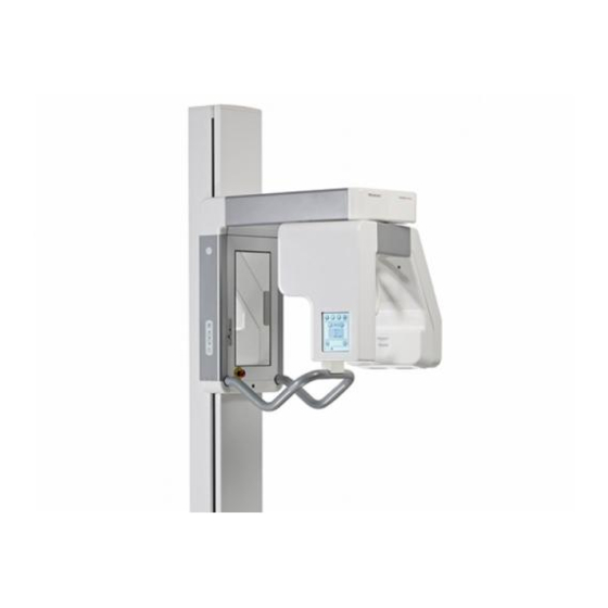
® 2. Unit Description CRANEX Novus e 2. Unit description 2.1 The CRANEX Novus e ® The CRANEX Novus e extraoral x-ray unit is designed ® to take exposures of the dento-maxillofacial region. The unit cannot be used to take x-ray exposures of any other part of the human anatomy. -
Page 20: The Main Parts And Assemblies
® CRANEX Novus e 2. Unit Description 2.2 The main parts and assemblies Motorized carriage Emergency stop button - Press to stop, rotate to release Exposure switch On / Off switch (rear of the column) Column CCD sensor Tubehead Tubehead (7) + CCD sensor (6) = Rotating unit PC with MDD approved dental imaging software Service Manual... - Page 21 ® 2. Unit Description CRANEX Novus e Patient positioning mirror Frankfort light Midsaggital light Focal through light Head support Patient handles Chin support A. Chin rest and bite block B. Chin rest and lip holder C. Lip support Service Manual...
- Page 22 ® CRANEX Novus e 2. Unit Description Side control panel Lights key - switches the patient positioning lights on and off Up / down keys Return key, drives rotating unit to the patient in/out position (PIO) Main control panel Program keys - adult pan, child pan, TMJ, bitewing (optional) kV selection keys Exposure values Service key...
-
Page 23: Unit Dimensions
® 2. Unit Description CRANEX Novus e 2.3 Unit dimensions Service Manual... -
Page 24: Mechanical Description
® CRANEX Novus e 2. Unit Description 2.4 Mechanical description The unit comprises a column, a motorized carriage, an upper shelf, a rotating unit and a patient support assembly. The column is permanently fi xed to the wall, using wall bracket and, if required or necessary to the fl... - Page 25 ® 2. Unit Description CRANEX Novus e Inside the tubehead there is the x-ray tube. It is a fi xed tungsten anode type. The patient support assembly is attached to the bot- tom of the vertical carriage. It comprises handgrips for the patient to hold and the patient support.
-
Page 26: Electrical Description
® CRANEX Novus e 2. Unit Description 2.5 Electrical description Circuit boards Circuit boards are described in detail in section 3. Cir- cuit Boards. Power supply Mains voltage is supplied to P1910 PFC Power Supply Board via L1600 Z-Motor Driver. P1910 supplies power to L1800 Generator Board and L1500 Power Supply board which supplies low voltages to all the other circuit boards. -
Page 27: Unit Control
® 2. Unit Description CRANEX Novus e Unit control The unit is controlled by a microprocessor on L1200 (CPU board). It continually monitors and controls the operation of the unit. A serial peripheral interface com- munication protocol (SPI - RS485) and direct digital I/O are used to monitor most of the unit functions. -
Page 28: Exposure Logic
® CRANEX Novus e 2. Unit Description Exposure logic An exposure can only be taken when the unit is in the ready state (the exposure ready light on the control panel is on) and the exposure button is pressed and held down. -
Page 29: Position Control
® 2. Unit Description CRANEX Novus e Position control The position of the rotating unit (R-movement) is moni- tored by optosensors on L2100 (Rotation Position Sen- sor Circuit). The optosensors indicate in which sector the rotating unit is. The optosensors ensure that the rotating unit is in the correct position, start or PIO (Pa- tient In/Out), for an exposure. - Page 30 ® CRANEX Novus e 2. Unit Description Radiation striking the CCD sensor is converted to vis- ible light which is detected by the CCD cell. A binning procedure is carried out on individual pixels, i.e. two ad- jacent pixels in a row and column (2 x 2 binning) forms one large pixel (96μm x 96μm).
-
Page 31: Wiring Diagrams - Overview
® 2. Unit Description CRANEX Novus e 2.6 Wiring diagrams - overview Service manual... - Page 32 ® CRANEX Novus e 2. Unit Description Service manual...
- Page 33 ® 2. Unit Description CRANEX Novus e Service manual...
-
Page 34: Block Diagram
® CRANEX Novus e 2. Unit Description 2.7 Block diagram Service manual... -
Page 35: Fuse Diagram
® 2. Unit Description CRANEX Novus e 2.8 Fuse diagram Service manual... -
Page 36: Circuit Boards
® CRANEX Novus e 3. Circuit Boards - L900, display adapter 3. Circuit Boards NOTE: An asterisk (*) after a signal name indicates an active low-level signal. 3.1 L900, Display adapter L900 - Location In the rotating unit on the CCD sensor side. To access remove sensor external cover. - Page 37 ® 3. Circuit Boards - L900, CCD display adapter CRANEX Novus e L900 - Field replaceable parts None L900 - Description L900 is a display adapter/interface board that controls the display (touch screen interface). L900 reads touch screen data and sends it to L1200 CPU board via the SPI interface.
-
Page 38: L1200 Cpu Board
® CRANEX Novus e 3. Circuit Boards - L1200, CPU Board 3.2 L1200 CPU Board L1200 - Location In rotating unit on the CCD sensor side. To access re- move the sensor external cover (see section 7.1). L1200 - Field replaceable parts None. - Page 39 ® 3. Circuit Boards - L1200, CPU Board CRANEX Novus e L1200 - Description The CPU board controls the unit. It controls the rota- tion and Z movements, the operation of the X-ray tube and reads the signals from the touch panel. It uses an embedded microcontroller on an Altera Cyclone FPGA circuit.
- Page 40 ® CRANEX Novus e 3. Circuit Boards - L1200, CPU Board L1200 - Block Diagram Service manual...
-
Page 41: L1500, Ccd Power Supply
® 3. Circuit Boards - L1500, CCD Power Supply CRANEX Novus e 3.3 L1500, CCD Power Supply L1500 - Location In the rotating unit on the the CCD sensor side. To access remove sensor external cover. L1500 - Field replaceable parts None. - Page 42 ® CRANEX Novus e 3. Circuit Boards - L1500, CCD Power Supply L1500 - Description L1500 supplies different voltages to most of the circuit boards in the unit. L1500 receives +27V5 and -20V from P1910 PFC and regulates these voltages to produce the other voltages that the unit requires.
- Page 43 ® 3. Circuit Boards - L1500, CCD Power Supply CRANEX Novus e L1500 - Block diagram Service manual...
- Page 44 ® CRANEX Novus e 3. Circuit Boards - L1500, CCD Power Supply L1500 - Indicator LEDs Colour Indicates green +15V_CCD on green +3.0V_CCD on green +3.3V_CCD on green +5V on green +5.0V_CCD on green -9.4V_CCD on green +24V on green +3.3V on L1500 - Test Points Number...
-
Page 45: L1600, Z-Motor Driver
® 3. Circuit Board - L1600, Z-Motor Driver CRANEX Novus e 3.4 L1600, Z-Motor Driver L1600 - Location On the upper shelf. To access remove shelf upper cover (see section 7.1). Service manual... - Page 46 ® CRANEX Novus e 3. Circuit Boards - L1600, Z-Motor Driver L1600 - Field replaceable parts NOTE: The fuses used MUST be the approved type, UL listed and CSA certifi ed. Approved fuses: Fuse F1 2AT/250VAC Cooper Bussmann MDL-2 2AT/250VAC Littelfuse 0313002 HXP Fuse F2 8AF/250V Littelfuse 0312008 312 series 8AF/250V Cooper Bussman AGE...
- Page 47 ® 3. Circuit Board - L1600, Z-Motor Driver CRANEX Novus e L1600 - Block diagram Service manual...
- Page 48 ® CRANEX Novus e 3. Circuit Boards - L1600, Z-Motor Driver L1600 - Indicator lamp Lamp Function Indicates LA1 GLIM AC indicator lamp L1600 receiving line voltage. L1600 - Indicator LEDs Colour Indicates green +5V on green ZACT-movement key pressed green ZON on ESTOP on.
-
Page 49: L1700 Connector Board
® 3. Circuit Boards - L1700, Connector Board CRANEX Novus e 3.5 L1700 Connector Board L1700 - Location In the rotating unit on the the CCD sensor side. To access remove sensor external cover. Service manual... - Page 50 ® CRANEX Novus e 3. Circuit Boards - L1700, Connector Board L1700 - Field replaceable parts None. L1700 - Description L1700 routes most of the signals to the other boards. L1700 receives signals from the tubehead (kVfb, mafb, and tubeheat) and scales the voltage swing (0…+5V) linearly to (1.25V…3.75 V) which is the input for the A/D converter on the CPU board.
- Page 51 ® 3. Circuit Boards - L1700, Connector Board CRANEX Novus e L1700 - Block Diagram Service manual...
-
Page 52: L1800, Generator Board
® CRANEX Novus e 3. Circuit Boards - L1800, Generator Board 3.6 L1800, Generator Board DANGER: HIGH VOLTAGE WARNING: Do not touch the Generator Board until the capaci- tors have discharged. After switching the unit off wait 10 minutes for the capacitors to discharge. When LED H1 goes out the capacitors are dis- charged. - Page 53 ® 3. Circuit Boards - L1800, Generator Board CRANEX Novus e L1800 - Description The Generator board receives kV and mA reference signals from L1200 as PWM modulated signal. Based on the kV-reference value, the Generator board gener- ates the corresponding high voltage between the cath- ode and anode of the x-ray tube.
- Page 54 ® CRANEX Novus e 3. Circuit Boards - L1800, Generator Board L1800 - Block diagram Service manual...
- Page 55 ® 3. Circuit Boards - L1800, Generator Board CRANEX Novus e L1800 - Indicator lights Colour Indicates green +380V (capacitors charged) green +15V yellow Exposure Tube fail yellow Preheat green +15V_HVGND L1800 - Test Points Number Signal Value +27V5 +5V FILTERED MAPWM +15V NOT USED NOT USED...
-
Page 56: P1910, Pfc Board
® CRANEX Novus e 3. Circuit Boards - P1910, PFC Board 3.7 P1910, PFC Board P1910 - Location DANGER: High voltage on this board. Do not touch this board when the unit is switched There is high voltage on the large heat sink on this board when the unit is switched on. - Page 57 ® 3. Circuit Boards - P1910, PFC Board CRANEX Novus e P1910 - Description The P1910 PFC (Power Factor Correction) power sup- ply board generates the supply voltages for the unit. This board works with mains voltages between 100VAC to 240VAC, 50/60Hz. The board produces the +380Vdc for the generator board.
- Page 58 ® CRANEX Novus e 3. Circuit Boards - P1910, PFC Board P1910 - Block diagram Service manual...
- Page 59 ® 3. Circuit Boards - P1910, PFC Board CRANEX Novus e P1910 - Indicator LEDs Colour Indicates green +380V green +27V5 green +20V green 17V_HVGND green -15V P1910 - Test Points None Service manual...
-
Page 60: L1300 Interface Board
® CRANEX Novus e 3. Circuit Boards - L1300, Interface Board 3.8 L1300 Interface Board L1300 - Location At the rear of the column near the base. L1300 - Field replaceable parts None. L1300 - Description L1300 serves as an external interface to the outside environment. - Page 61 ® 3. Circuit Boards - L1300, Interface Board CRANEX Novus e L1300 - Indicator LEDs None. L1300 - Test Points None. Service manual...
-
Page 62: L2100 Rotation Position Sensor Board
® CRANEX Novus e 3. Circuit Boards - L2100, Rot. pos. sen. 3.9 L2100 Rotation Position Sensor Board L2100 - Location Inside the rotating unit under the head support. To access, remove the head support and then the lower protective cover (see section 7.1). L2100 - Field replaceable parts None. - Page 63 ® 3. Circuit Boards - L2100, Rot. pos. sen. CRANEX Novus e L2100 - Indicator LEDs None. L2100 - Test Points None. Service manual...
-
Page 64: R5100, 3-Phase Microstepper Driver
® CRANEX Novus e 3. Circuit Boards - R5100, 3-Phase Microstepper Driver 3.10 R5100, 3-Phase Microstepper Driver R5100 - Location Inside the rotating unit, above the head support. To ac- cess, remove the head support, lower protective cover (see section 7.1). R5100 - Field replaceable parts None. - Page 65 ® 3. Circuit Boards - R5100, 3-Phase Microstepper Driver CRANEX Novus e R5100 - Indicator LEDs Colour Indicates green +5V on green +24V on R5100 - Test Points Number Description Value VREF 0.97V ±0.1V; when HICUR* = '1' 1.95V ±0.1V; when HICUR* = '0' (default value) +5V freq <15kHz +5V active, 0V idle +5V when idle or when moving to the...
-
Page 66: Ccd Sensor / Filter Board
® CRANEX Novus e 3. Circuit Boards - CCD Sensor / Filter 3.11 CCD Sensor / Filter board CCD / Filter - Location In rotating unit. To access, remove the sensor inner cover (see section 7.1). CCD - Field replaceable parts None. - Page 67 ® 3. Circuit Boards - CCD Sensor / Filter CRANEX Novus e CCD - Indicator lights Remove the covers from the CCD side of the rotating unit On the rear of the CCD sensor there are a number of LEDs that indicate the status of the CCD sensor. Colour Indicates Power...
- Page 68 ® CRANEX Novus e 3. Circuit Boards - CCD Sensor / Filter Yellow +15V, +3V and –9.4V LED CCD gate voltages LIMITS: +15V between +13.5V to +16.5V +3V between +2.4V and +3.6V -9V between -9.92V and -9.17V Another required voltage is μC +3.3V. It is used to power the microcontroller, +3.3VD_CCD.
- Page 69 ® 3. Circuit Boards - CCD Sensor / Filter CRANEX Novus e Filter - Field replaceable parts None. Filter - Description Sensor fi lter board is a low pass type RF-fi lter board which fi lters electromagnetic interference (EMI) from all CCD-signal and and power supply lines.
-
Page 70: Troubleshooting
® CRANEX Novus e 4. Troubleshooting 4. Troubleshooting 4.1 Initial checks Restarting the unit If the unit fails to operate, does not operate correctly or if an error code appears, switch the unit off, wait for a few seconds and then switch the unit on again. If the unit still does not operate correctly or the error message reappears, follow the troubleshooting procedures de- scribed here to correct the problem. -
Page 71: Checking Cables And Connectors
® 4. Troubleshooting CRANEX Novus e Checking cables and connectors Visually check cables for mechanical damage, cuts, damaged insulation and twists. If a cable is damaged in any way replace it. If there is no obvious mechanical damage to a cable but you think that it may be faulty, use a digital multimeter (DMM) to check the resistance of the different wires within the cable. -
Page 72: Problems During Start Up
® CRANEX Novus e 4. Troubleshooting 4.2 Problems during start up Nothing happens when the unit is switched on The on/off switch light does not come on. CAUSE A Power cut. SOLUTION A Check to see if the power has been cut off. CAUSE B Unit not connected to the main power supply SOLUTION B... - Page 73 ® 4. Troubleshooting CRANEX Novus e 2. L1600 (Z-motor driver) supplies mains voltage to the P1910 (FPC board) via a fi lter. Check that LEDs A5 = +380V, A8 = 27V5, A9 = -20V, A10 = +17V and A15 = -15V on P1910 are on. If they are not on check fuse FH2, and replace if blown.
-
Page 74: Error E3 (Cfg Data Lost)
® CRANEX Novus e 4. Troubleshooting CAUSE B The display backlight power level has been set to OFF. SOLUTION B Use the service terminal to change the display backlight power level. Error E3 (CFG Data lost) CAUSE L1200, CPU board, has lost the calibration data and settings. -
Page 75: Error E8 (File System Failure)
® 4. Troubleshooting CRANEX Novus e Error E8 (File system failure) CAUSE GUI graphics are corrupted. SOLUTION Update the GUI graphics. Error E16 (Z lift not allowed due to duty cycle) CAUSE Z-motor over heated. SOLUTION Allow motor to cool down. Error E18 (Display not connected) Check Service Assistant for information about this error code... -
Page 76: Error E19 (Exposure Switch Stuck Down)
® CRANEX Novus e 4. Troubleshooting Error E19 (Exposure switch stuck down) CAUSE Exposure switch stuck down during unit start up. SOLUTION Switch the unit off and check that the exposure switch is not stuck in the exposure position. Switch the unit on again. -
Page 77: Problems While Preparing The Unit For An Exposure
® 4. Troubleshooting CRANEX Novus e 4.3 Problems while preparing the unit for an exposure Image of emergency button appears on main display CAUSE The emergency switch has been pressed down. NOTE: LED D4 (ESTOP on) on L1600 will come on when the emergency switch is pressed down. -
Page 78: Rotating Unit Stop Rotating, No Error Code
® CRANEX Novus e 4. Troubleshooting Rotating unit stop rotating, no error code CAUSE A Faulty R5100 or stepper motor. SOLUTION A Check the cables connected to R5100. If ok, replace R5100. If the unit still does not work, replace the stepper motor. Patient positioning light(s) do not come on The patient positioning lights (lasers) come on when: - the light key is pressed... -
Page 79: Up/Down (Z-Motor) Keys Do Not Work
® 4. Troubleshooting CRANEX Novus e CAUSE C (Unlikely) All the lights are faulty. SOLUTION C Replace all the lights, they are connected to L1600 (Z- motor driver) and then realign them. Refer to the instal- lation manual. Up/down (Z-motor) keys do not work CAUSE A The emergency switch has been pressed down. - Page 80 ® CRANEX Novus e 4. Troubleshooting CAUSE C The side control panel (up/down keys) has failed SOLUTION C If D2 and D3 on L1600 do not come on when the up/ down keys are pressed it indictes that the side control panel or the cable from the control panel are faulty and must be replaced.
-
Page 81: Problems During Exposure
® 4. Troubleshooting CRANEX Novus e 4.4 Problems during exposure Nothing happens when the exposure button is pressed CAUSE A Exposure switch failed. SOLUTION A Replace the exposure switch. CAUSE B Unit not in ready mode,no PC-connection or no active client reserving the unit. -
Page 82: Error Codes E0, E1 And E2
® CRANEX Novus e 4. Troubleshooting Error codes E0, E1 and E2 NOTE: Error codes E0, E1, E2 all indicate that the tubehead and/or Generator board are not functioning correctly. E0 (Tube arcing) CAUSE Tube arcing. NOTE: Check the tube fail LED (red) in the upper right corner of the Generator board. - Page 83 ® 4. Troubleshooting CRANEX Novus e If the "actual" values differ by more than ±2kV from the target values, it indicates that there is a problem and the tubehead must be recalibrated. From the Service Assistant select calib and calibrate the tubehead.
-
Page 84: Error E10 (Ccd Initialization/Confi Guration Failure)
® CRANEX Novus e 4. Troubleshooting Connect a DMM to TP12 (kVref) and TP17 (GND) on L1800 and take an exposure. Then connect the DMM to TP11 (mAref) and TP17 (GND) and take another exposure. The values for the reference signals can be counted as described in chapter 3.6 L1800, Generator Board - Test points If the reference values are correct, but feed back val-... -
Page 85: Error E12 (Ccd Line Failure)
® 4. Troubleshooting CRANEX Novus e Error E12 (CCD line failure) CAUSE The image data fl ow from the CCD sensor to L1200 was interrupted during the exposure. SOLUTION Refer to the trouble shooting information given in error code E11. Error E13 (CCD confi... -
Page 86: Problems After Exposure
® CRANEX Novus e 4. Troubleshooting 4.5 Problems after exposure Error E4 (Tubehead too hot) CAUSE A The tube head has overheated (> 55°). SOLUTION A Wait for the tubehead to cool down. When the tubehead reaches the right temperature the error message will automatically disappear. -
Page 87: Bad Quality Images
® 4. Troubleshooting CRANEX Novus e 4.6 Bad quality images Bad quality images can be due to one or more of the following: incorrect patient positioning a badly aligned unit the CCD sensor is not calibrated Incorrect patient positioning If the unit is producing bad quality images, fi rst make sure that the user is positioning the patients correctly. -
Page 88: S2Terminal And Service Commands
® CRANEX Novus e 5. S2terminal and service commands 5. S2terminal and service commands 5.1 Using the S2terminal The S2terminal utility includes a number of commands that allow the unit to be tested and confi gured during installation, set up and service. To open the S2terminal: 1. - Page 89 5. S2terminal and service commands CRANEX ® Novus e 8. Key in "help" and press ENTER. _________________________________________________________________ help _________________________________________________________________ A list of commands will appear. NOTE: The list may vary according to unit version ------------------------------------------------------------------------------------------------------------- DESCRIPTION (* available also in normal mode) calib calibrates generator references and preheat conf...
- Page 90 ® CRANEX Novus e 5. S2terminal and service commands 9. To select a function key in the function name, for example exp, into the fi eld at the bottom of the service terminal. ____________________________________ >exp ____________________________________ Information about the selected function will ap- pear at the bottom of the list of functions.
-
Page 91: The Service Commands
5. S2terminal and service commands CRANEX ® Novus e 5.2 The Service commands ------------------------------------------------------------------------------------------------------- COMMAND DESCRIPTION calib calibrates generator references and preheat Calibrates the voltage (kV), current (mA) and preheat (mApreh) reference values for the tubehead and gen- erator board. This calibration procedure must be carried out when the - tubehead - generator... - Page 92 ® CRANEX Novus e 5. S2terminal and service commands conf display summary of confi guration data Displays all the current confi guration parameters of the unit. The fi gures in brackets (1) are factory settings. If you wish to restore the factory settings use the re- store command.
- Page 93 5. S2terminal and service commands CRANEX ® Novus e display display power level (<value>) Sets the power level of the display. Upper or lower case text can be used. NORMAL HIGH endu endurance test, drives rotating unit 75 rounds Automatically drives the rotating unit through 75 rotation cycles.
- Page 94 ® CRANEX Novus e 5. S2terminal and service commands NOTE: The kV value used for the exposure will be the one selected before entering the service mode. The kV value cannot be changed while the unit is in the service mode.
- Page 95 5. S2terminal and service commands CRANEX ® Novus e confi gure ip address Displays the current IP address of the unit. To change the IP address enter the new one, ____________________________________________ > ip aaa.bbb.ccc.ddd (the new IP address) ____________________________________________ and then press Enter. After changing the IP address of the unit, communica- tion between the unit and the PC will be lost and the link to the PC will have to be reconfi...
- Page 96 ® CRANEX Novus e 5. S2terminal and service commands logsign make a service signature for current events Allows a short note to be added to a log entry. Add the note, ____________________________________________ > logsign Note ..____________________________________________ and then press Enter. The note will appear in the log. print mac address Displays the current MAC address of the unit.
- Page 97 5. S2terminal and service commands CRANEX ® Novus e optotest prints optosensor values for 30 seconds Allows L2100 to be checked. Optosensors on L2100 monitor the position of the rotating unit. The "optotest" command displays, for 30 seconds, val- ues that indicate the position of the L2100 board. When you manually rotate the rotating unit the values should change, ____________________________________________...
- Page 98 ® CRANEX Novus e 5. S2terminal and service commands printgen prints the generator settings Displays the settings that are stored in the confi guration memory. quit quit service terminal Exits and closes the service terminal. reset reboot the unit Reboots the unit. restore restore factory confi...
- Page 99 5. S2terminal and service commands CRANEX ® Novus e stillmode still image exposure Generates x-rays and activates the CCD sensor but the rotating unit does not move. It is used to check the beam alignment during unit installation (refer to the Installation manual for more information).
-
Page 100: Updating Unit Fi Rmware, Core And Display Graphics
6. Updating the fi rmware and the core 6. Updating unit fi rmware, core and display graphics 6.1 Firmware zip fi le SOREDEX will supply a zip fi le containing all the neces- sary fi les for the upgrade. The zip fi le will include the following: s2terminal for the update Firmware fi... -
Page 101: Replacing Parts
® 7. Replacing parts CRANEX Novus e 7. Replacing parts. 7.1 Removing covers Instruction on how to remove the ss cover are in section 7.6 Replacing the z-carriage motor. Service manual... -
Page 102: Replacing The Tubehead
® CRANEX Novus e 7. Replacing parts 7.2 Replacing the tubehead Tools required The normal installation and alignment tools. Replacement parts New tubehead Tubehead label Replacing the tubehead 1. Switch the unit off and disconnect it from the main power supply. 2. - Page 103 ® 7. Replacing parts CRANEX Novus e 3. Remove the EMC cover (4 screws), and then the clear plastic PFC and generator protec- tion insulator (3 screws) 4. Disconnect all cables and the ground cable from the tubehead. Service manual...
-
Page 104: Calibrating The Tube Head And Checking The Alignment
® CRANEX Novus e 7. Replacing parts 5. Remove the four (4) nuts that hold the tube- head to the rotating unit frame and remove the tubehead. 6. Attach the new tubehead to the rotating unit frame with the four (4) nuts. 6. -
Page 105: Replacing The Ccd Sensor
® 7. Replacing parts CRANEX Novus e 7.3 Replacing the CCD sensor After replacing the CCD sensor, realign the unit (refer to section 8. Aligning the unit). 7.4 Replacing the collimator After replacing the collimator, realign the unit (refer to section 8. -
Page 106: L1800 Generator Board - Additional Instructions
® CRANEX Novus e 7. Replacing parts L1800 Generator board - additional instructions After replacing the board use the Service Assistant to recalibrate the unit: - calib Refer to section 5. Service Assistant and Service Functions. L1700 Connector board - additional instructions After replacing the board use the Service Assistant to recalibrate the unit: - calib... -
Page 107: Replacing The Z-Motor
® 7. Replacing parts CRANEX Novus e 7.6 Replacing the z-motor CAUTION: DO NOT attempt to replace the z-motor while the unit is in the vertical position, either when attached to the wall or to an exhibition base. The rotating unit must be removed from the z-carriage and then the unit removed from the wall and placed on the fl... - Page 108 ® CRANEX Novus e 7. Replacing parts 3. Remove the upper shelf top cover (2 x M4 screws) from the upper shelf. 3. Disconnect all the cables that connect the rotating unit to the L1600 - Z-motor board. Also disconnect the Ethernet cable and the ground leads.
- Page 109 ® 7. Replacing parts CRANEX Novus e Loosen the 4 nuts that hold the rotating unit to the upper shelf and then slide the rotating unit off of the upper shelf and place it on the ground. 5. CAUTION: HEAVY OBJECT; THE FOLLOW- ING TASK REQUIRES TWO PEOPLE.
- Page 110 ® CRANEX Novus e 7. Replacing parts 7. Carefully slide the column upper front plate off of the column. Be careful not to damage the surface fi nish. Service manual...
- Page 111 ® 7. Replacing parts CRANEX Novus e 8. Remove the two nuts that hold the safety nut to the bottom of the z-carriage assembly and then slide the z-carriage upwards away from the safety nut. 9. Remove the terminal plate from the column assemble (2 screws) and then disconnect the motor power supply cables from the terminal block and the ground cable from the motor.
- Page 112 ® CRANEX Novus e 7. Replacing parts 10. Remove the three nuts that hold the z-motor to the bottom of the column assembly and remove the motor. 11. Install a new z-motor, connect all the cables and then replace all part and covers. 12.
-
Page 113: Aligning The Unit
® 8. Aligning the unit CRANEX Novus e 8. Aligning the unit After replacing one of more of the following: tubehead, collimator, CCD sensor, the alignment of the unit must be checked and if required adjusted. 8.1 Removing the covers 1. - Page 114 ® CRANEX Novus e 8. Aligning the unit If the beam (black line) is not in the middle of the CCD aperture (the gray area), the position of the CCD Sensor must be adjusted to the right or left. If the CCD aperture (gray area) is not vertical, the CCD sensor must be rotated slightly until it is vertical.
-
Page 115: Checking And Adjusting The Position Of The Collimator
® 8. Aligning the unit CRANEX Novus e 8.3 Checking and adjusting the position of the collimator Checking and Adjusting the Center of Rotation The centre of rotation is correct when the beam strikes the alignment plate at the same point (not necessarily the center) when the tubehead is po- sitioned fi... - Page 116 ® CRANEX Novus e 8. Aligning the unit 6. Protect yourself from radiation. Darken the room and then position yourself behind and below the tubehead. Press and hold down the exposure switch. Make a note of where the beam strikes the alignment plate.
- Page 117 ® 8. Aligning the unit CRANEX Novus e Compare the fi rst beam position with the sec- ond beam position and determine how far and in which direction the Collimator must be ad- justed. 9. Remove the screwdriver from the locking hole. Adjusting the position of the collimator 1.
-
Page 118: Checking And Adjusting The Chin Support
® CRANEX Novus e 8. Aligning the unit 8.4 Checking and adjusting the Chin Support The Chin Support is in the correct positioned when the beam strikes the middle line on the alignment plate when the rotating unit is parallel to the side of the upper shelf. - Page 119 ® 8. Aligning the unit CRANEX Novus e 5. Protect yourself from radiation. Darken the room and then position yourself behind and below the tubehead. Press and hold down the exposure switch. Check how far the radiation beam is away from middle line of the alignment plate.
-
Page 120: Checking And Adjusting The Focal Trough
® CRANEX Novus e 8. Aligning the unit 3. Loosen the set screw that holds the Lower Set screw Shelf Screw (the horizontal screw) in position and turn it to adjust the position of the Chin Support Holder. CAUTION: DO NOT loosen the screws (2) that attach the Chin Rest Support to the Patient Handle. - Page 121 ® 8. Aligning the unit CRANEX Novus e Adjusting the position of the focal trough 1. In the upper shelf loosen the two nuts that hold the Rotation Bearing in place. Turn the adjusting screw to adjust the position of the the Rotating Unit.
-
Page 122: Recheck The Alignment
® CRANEX Novus e 8. Aligning the unit 8.6 Recheck the alignment 1. Take a ball-pin exposure to confi rm that the unit is now correctly aligned. Refer to the Installation Manual section 5. Checking the alignment. If the unit needs realigning, adjust accordingly. 8.7 Calibrating the CCD sensor 1.
Need help?
Do you have a question about the CRANEX Novus e and is the answer not in the manual?
Questions and answers
How do I calibrate the measurement feature with a metal ball bearing?
To calibrate the measurement feature on the Soredex CRANEX Novus e using a metal ball bearing:
1. Take a ball-pin exposure to confirm that the unit is correctly aligned.
2. If alignment is incorrect, adjust the Rotating Unit:
- Loosen the two nuts holding the Rotation Bearing in place.
- Turn the adjusting screw counterclockwise to move the unit toward the column or clockwise to move it away.
- If the middle ball in the image is too wide, turn the screw clockwise; if too narrow, turn it counterclockwise.
- Repeat until the middle ball appears round within tolerance.
3. Replace the Top Cover Plate and Front Panel.
4. Recheck the alignment by taking another ball-pin exposure.
5. If further adjustment is needed, repeat the process until the image is correctly aligned.
This answer is automatically generated