Table of Contents
Advertisement
Advertisement
Table of Contents

Related Manuals for AC Infinity AIRTITAN Series


Summary of Contents for AC Infinity AIRTITAN Series
- Page 1 AIRTITAN SERIES CRAWLSPACE AND BASEMENT VENTILATION FANS USER MANUAL USER MANUAL...
- Page 3 WELCOME Thank you for choosing AC Infinity. We are committed to product quality and friendly customer service. If you have any questions or suggestions, please don’t hesitate to contact us. Visit www.acinfinity.com and click contact for our contact information. EMAIL LOCATION support@acinfinity.com...
- Page 4 MANUAL CODE AT2208X3 PRODUCT MODEL UPC-A AIRTITAN S3 AC-ATS3 819137023727 AIRTITAN S7 AC-ATS7 819137023734 AIRTITAN T3 AC-ATT3 819137020467 AIRTITAN T7 AC-ATT7 819137020474 AIRTITAN T8 AC-ATT8 819137020481 AIRTITAN T8-N AC-ATT8-N 819137020498 EC models CANNOT be daisy chained with DC models. See pages 24-25 for more information on daisy-chaining fans and safety precautions.
-
Page 5: Manual Index
Adding More Devices ..............Page 25 Programming ................. Page 26 Other Settings ................Page 45 Download the App ................. Page 46 Add a Device ................. Page 47 ....................Page 50 Other AC Infinity Products ............. Page 55 Warranty ..................Page 56... -
Page 6: Product Warning
PRODUCT WARNING TO REDUCE THE RISK OF FIRE, ELECTRIC SHOCK, OR INJURY TO PERSONS, OBSERVE THE FOLLOWING: Ensure your power source conforms to the electrical requirements of this product. Check your local code restrictions for additional safety measures that may be needed for a proper code compliant installation. -
Page 7: Key Features
KEY FEATURES HEAVY DUTY BUILD QUIET OPERATION DUAL BALL BEARINGS Fans are specially sealed for high PWM-controlled motor provides Each fan contains long-life resistance to dust particles and precise speed control, reduced ball bearings rated at 67,000 liquids, including water splashes rotor noise, and runs on energy hours, enabling the fan to be and high-pressure water jets. -
Page 8: Product Contents
PRODUCT CONTENTS AIRTITAN T8 and AIRTITAN T8-N SENSOR SYSTEM PROBE (x1) (x1) AIRTITAN S3 and S7 SPEED UIS EXTENSION WOOD SCREWS SYSTEM CONTROLLER CORD (M-M) (WALL HANG) (x1) (x1) (x1) (x1) AIRTITAN T3 and T7 SMART SENSOR WOOD SCREWS UIS EXTENSION SYSTEM CONTROLLER PROBE... - Page 9 CHANGING FAN DIRECTION AIRTITAN S3/S7 and T3/T7 STEP 1 Unplug the unit before flipping the internal fan, and double check to make sure that it is completely unpowered. Remove the front and back screws using a Phillips screwdriver to AIRTITAN S3/T3 illustration shown above. separate the internal fan from the fan shell and front plate.
- Page 10 CHANGING FAN DIRECTION AIRTITAN S3/S7 and T3/T7 STEP 3 Reapply the screws to secure the shell and back plate to reassemble the fan. AIRTITAN S3/T3 illustration shown above. NOTE: For AIRTITAN T8 Series, we offer both intake and exhaust configurations.
-
Page 11: Fan Mounting
FAN MOUNTING STEP 1 Remove any existing grilles, vents, or covers on ventilation opening where you wish to install the fan unit. STEP 2 Position the fan unit over the ventilation opening. Depending on the model, the unit may be facing towards or away from the wall. - Page 12 FAN MOUNTING STEP 3 (Foundation Block Mounting) To install the unit onto a foundation brick or block, mark the mounting hole locations using the four corners of the metal face plate. Then drill 5/16" holes with a drill bit. Install wall anchors into openings and secure the unit into the wall with four screws.
- Page 13 POWERING AND SETUP AIRTITAN S3/S7 STEP 1 Use the included UIS M-M extension cord to connect the fan's EC Motor box to the S-Series controller. STEP 2 Plug the fan's power cord into an AC power outlet to power it and the controller.
- Page 14 POWERING AND SETUP AIRTITAN T3/T7 STEP 1 Use the included UIS M-M extension cord to connect the fan's EC Motor box to one of the controller's ports. STEP 2 Plug the sensor probe into the controller’s 3.5mm jack. Route the probe head to spot areas as needed.
- Page 15 POWERING AND SETUP AIRTITAN T3/T7 STEP 3 Plug the fan's power cord into an AC power outlet to power it and the controller. STEP 4 You may use the included tie mounts and wire ties to manage the cords. Secure the tie mounts onto a surface. Loop the wire ties around the cords into the tie mounts.
- Page 16 POWERING AND SETUP AIRTITAN T8/T8-N STEP 1 To set up temperature monitoring, plug the male connector of the thermal probe into the designated probe port located at the bottom side of the fan unit. STEP 2 Plug the fan's power cord into an AC power outlet to power it.
-
Page 17: Controller Mounting
CONTROLLER MOUNTING AIRTITAN S3/S7 STEP 1 — WALL MOUNTING Locate a spot free of obstruction and secure the anchor into your wall. Twist the wood screw into the anchors. STEP 2 — WALL MOUNTING Hang the controller by the screw using the hole on the backside. -
Page 18: Magnet Mounting
CONTROLLER MOUNTING AIRTITAN S3/S7 MAGNET MOUNTING Mount the controller on a steel surface using the magnet located behind the label. - Page 19 CONTROLLER MOUNTING AIRTITAN T3/T7 STEP 1 — WALL MOUNTING Locate a spot free of obstruction and secure the anchors into your wall. Twist the wood screws into the anchors. STEP 2 — WALL MOUNTING Hang the controller by the screws using the holes on the backside.
- Page 20 CONTROLLER MOUNTING AIRTITAN T3/T7 MAGNET MOUNTING You may also mount the controller onto a steel surface using the magnet located behind the label. CORD ARRANGEMENT Cords may be routed into or outside of the kickstand grooves, and through a cut hole behind the controller.
- Page 21 CONTROLLER MOUNTING AIRTITAN T3/T7 KICKSTANDING Open the stand behind the controller to set it tilted on your desktop.
- Page 22 Create independent timers and schedules for customized activation in your desired timeframe. Your grow system can be regulated using your controller hub or remotely on the AC Infinity app (paired with compatible controllers), where you will have access to automation programming and climate data.
-
Page 23: Extension Cable
The expansion dongle will allow you to connect 2 or 4 devices with a single port and can support additional dongles to create more expansion ports (up to 64 units supported with the use of 20 dongles). Intended for exclusive use with AC Infinity controllers built with UIS ports. UIS M - F... - Page 24 COMPATIBILITY The AIRTITAN T-Series includes the CONTROLLER 69, which is compatible with AC Infinity fan models that contain EC-motors. An AIRTITAN fan that uses an EC-motor will use a power brick while on that does not use an EC-motor will lack a power brick. Note that certain models that previously used DC-motors now contain EC-motors in updated builds.
-
Page 25: Adding More Devices
ADDING MORE DEVICES The CONTROLLER 69 is built with four ports that enable you to power and control multiple devices at the same time. See images below for a sample configuration. -
Page 26: Powering On/Off
PROGRAMMING S-SERIES FAN SPEED ADJUSTING The controller features a single button that controls the fan speed from 0-10. Pressing the speed button increases the fan speed in one unit increments. Pressing the button at the 10 setting will set the fan speed back to 0. Fan Speed Indicator POWERING ON/OFF... -
Page 27: Controller Mode
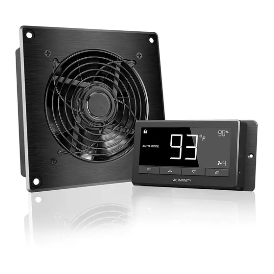
PROGRAMMING T-SERIES AIRTITAN T8/T8N Screen Display, and CONTROLLER 69 Display 2. MODE BUTTON 1. PORT BUTTON 3. SETTING BUTTON Cycles through the controller’s modes: Cycles through up to four Cycles through the OFF, ON, AUTO (4 triggers), TIMER to connected devices. Each device controller’s settings: DISPLAY, ON, TIMER to OFF, CYCLE (ON and is programmed independently, or... - Page 28 PROGRAMMING T-SERIES PORTS Pressing the port button will cycle through the controller’s available ports: ALL, 1, 2, 3, and 4. Dot indicates the current device. No digit is displayed if a device is not plugged into the corresponding port. ALL PORTS Navigate to the ALL port to set simultaneous programming for all connected devices.
- Page 29 PROGRAMMING T-SERIES CONTROLLER MODES Pressing the mode button will cycle through the controller’s available programming modes: OFF, ON, AUTO (4 triggers), TIMER TO ON, TIMER TO OFF, CYCLE (On and Off), and SCHEDULE (On and Off). OFF MODE Your devices will not run while in this mode. The OFF Mode setting also serves as the minimum level the other modes will run at while triggered OFF.
-
Page 30: Maximum Level
PROGRAMMING T-SERIES ON MODE Your devices will actively run at the level set here, regardless of the probe’s reading. The ON Mode setting also serves as the maximum level the other modes will run at. *Example shown MAXIMUM LEVEL Your devices will run at the level set in ON Mode, as the maximum level, when triggered ON, as well as in the AUTO Mode, CYCLE Mode, TIMER TO ON Mode, TIMER TO OFF... - Page 31 PROGRAMMING T-SERIES AUTO MODE (HIGH TEMPERATURE TRIGGER) Pressing the up or down button sets the high temperature trigger. The devices will activate if the probe’s reading meets or exceeds this threshold. Once triggered, the devices will gradually ramp up to the level set in ON mode.
- Page 32 PROGRAMMING T-SERIES AUTO MODE (LOW TEMPERATURE TRIGGER) Pressing the up or down button sets the low temperature trigger. The devices will activate if the probe’s reading meets or falls below this threshold. Once triggered, the devices will gradually ramp up to the level set in ON mode.
- Page 33 PROGRAMMING T-SERIES AUTO MODE (HIGH HUMIDITY TRIGGER) Pressing the up or down button sets the high humidity trigger. The devices will activate if the probe’s reading meets or exceeds this threshold. Once triggered, the devices will gradually ramp up to the level set in ON mode.
- Page 34 PROGRAMMING T-SERIES AUTO MODE (LOW HUMIDITY TRIGGER) Pressing the up or down button sets the low humidity trigger. The devices will activate if the probe’s reading meets or falls below this threshold. Once triggered, the devices will gradually ramp up to the level set in ON mode.
- Page 35 PROGRAMMING T-SERIES TIMER TO ON MODE Pressing the up or down button sets a countdown time. During the countdown, your device will be set to OFF. Once the timer ends, your device will trigger to turn on. If there is a level set in OFF Mode, the devices will run at that level during the countdown and when TIMER TO ON...
- Page 36 PROGRAMMING T-SERIES CYCLE MODE (ON AND OFF) 30min. Set an on duration and an off duration for the devices to cycle through continuously. Press 1hr. the up or down button to first set a duration for the devices to activate. Then press the mode button again and set a duration for the devices to deactivate.
- Page 37 PROGRAMMING T-SERIES SCHEDULE MODE (ON AND OFF) Sets an on clock-time and an off clock-time schedule for the devices to follow daily. Press the up or down button to first set up an on clock-time to trigger ON mode, then press the mode button to set an off clock-time to trigger OFF mode.
- Page 38 PROGRAMMING T-SERIES CONTROLLER SETTINGS Pressing the setting button will cycle through the controller’s available settings: DISPLAY, °F/ °C, CLOCK, CALIB. T°, CALIB. H%, TRANS. T°, and TRANS. H%. DISPLAY SETTING Adjusts the display brightness and auto-dimming. Press the up or down button to cycle through levels 1, 2, 3, A2 and A3;...
-
Page 39: Clock Setting
PROGRAMMING T-SERIES °F/°C SETTING Changes the displayed units to Fahrenheit or Celsius. Press the up or down button to cycle through F and C. All displayed units will automatically convert when adjusting this setting. CLOCK SETTING Adjusts the current clock time. Press the up or down button to increase or decrease the time. - Page 40 PROGRAMMING T-SERIES CALIBRATION TEMPERATURE SETTING Adjusts the temperature reading the sensor probe is measuring. Press the up or down button to increase or decrease the data figure in 2°F (or 1°C) increments. The calibration cycle ranges from -20°F to 20°F (or -10°C to 10°C) and will be applied to the sensor probe’s measurements.
- Page 41 PROGRAMMING T-SERIES TRANSITION TEMPERATURE SETTING Adjusts how gradually your device will shift between levels when triggered ON by the AUTO Mode’s temperature trigger. This will determine how much the probe temperature needs to increase to step up to the next level setting. The higher the transition setting is, the wider the temperature gap is between levels.
- Page 42 PROGRAMMING T-SERIES TRANSITION HUMIDITY SETTING Adjusts how gradually your device will shift between levels when triggered ON by the AUTO Mode’s humidity trigger. This will determine how much the probe humidity needs to increase to step up to the next level setting. The higher the transition setting is, the wider the humidity gap is between levels.
- Page 43 PROGRAMMING T-SERIES ALERT ICONS The alert icons are displayed at the top of the screen. Icons may flash when the controller signals an alert to notify you of any triggered function or alarm. ADVANCE PROGRAMMING Displays when an advance program set in the app is active. "ADV." will appear and override the controller if an automation program is in use.
- Page 44 PROGRAMMING T-SERIES BLUETOOTH Appears when the physical controller is connected to the app via Bluetooth. DISPLAY LOCK ALERT Displays when you lock the controller. The icon will flash and beep if you attempt to adjust the controller while it is still locked. TEMPERATURE/ HUMIDITY ALARM Flashes and beeps with alarm if the temperature/ humidity meet the trigger point set in the app.
-
Page 45: Other Settings
OTHER SETTINGS T-SERIES FACTORY RESET Holding the mode, up, and down buttons together for 5 seconds HOLD + will reset your controller and restore factory settings. This clears all user parameters in each controller mode and setting. CONTROLLER LOCK Holding the setting button will lock the controller in your current mode. -
Page 46: Download The App
Open the smart phone camera and scan the QR code below to download the AC Infinity app. Please visit our website at www.acinfinity.com for more information on the AC Infinity app. Please note: The AC Infinity App’s appearance and features are subject to change, and please refer to our website/QR for the latest instructions. -
Page 47: Add A Device
ADD A DEVICE SETUP AND PAIRING Power your device on before pairing your device with the app. Refer to pages 14-16 for more information regarding controller setup. Tap on the “+” tab to To launch the app, tap on the "Smart add your smart device. - Page 48 ADD A DEVICE Select CONTROLLER 69 to begin pairing. Hold the port button for 5 seconds to activate Bluetooth. Wait for the Bluetooth icon to start flashing on your controller’s screen.
- Page 49 ADD A DEVICE Tap DONE button to complete the Your controller will appear in your pairing process. smart device with a unique ID. E-E000E DONE Please note: When pairing the app around multiple controllers, move your mobile device closer to your desired controller.
- Page 50 What devices are compatible with the CONTROLLER 69? All AC Infinity devices that contain a UIS connector are compatible. If your AC Infinity device has a 4-pin Molex connector and an EC-Motor, it may still be compatible with the use of an UIS adapter to convert its connector to fit with the controller.
- Page 51 CONTROLLER 69 FAQ How do I stop my device from turning on and off too quickly in AUTO MODE? The figure set in the TRANSITION under SETTINGS will determine how the device ramps up in levels when triggered to run in AUTO MODE. Set a transition threshold X. For every multiple of X that has surpassed your trigger point, the device will increase by one level.
- Page 52 CONTROLLER 69 FAQ Will I be able to use this controller with my own fan? The CONTROLLER 69 is only compatible with AC Infinity fans that use EC-motors. Does the controller retain its settings after power is shut off? Yes. If the controller's power is cut off and is powered on afterwards, your settings will remain.
- Page 53 AIRTITAN FAQ Can I mount this crawlspace fan vertically? Yes. The AIRTITAN can be mounted in any orientation, including vertically. Can I splice the cables to extend them or use my own probe? We do not recommend hardwiring or splicing our fan's power wires. Such modifications may compromise electrical safety and will void this product's warranty.
- Page 54 AIRTITAN FAQ Does this fan include grilles for outside installation or duct tubes for wall installation? This product does not come included with ducting or grilles as accessories. Is this fan waterproof? The AIRTITAN is IP55 rated for resistance against splashing water, but it is not completely waterproof and should not be submerged in water.
- Page 55 AC INFINITY PRODUCTS Register Booster Fans The AIRTAP series is a line of register booster fans designed to quietly increase airflow coming from your central heat and air conditioning systems, increasing comfort for your home. Features a thermal controller with intelligent programming that will automatically adjust airflow strength in response to heating and cooling temperatures you have set.
-
Page 56: Warranty
WARRANTY This warranty program is our commitment to you, the product sold by AC Infinity will be free from defects in manufacturing for a period of two years from the date of purchase. If a product is found to have a defect in material or workmanship, we will take the appropriate actions defined in this warranty to resolve any issues. - Page 57 No part of the materials including graphics or logos available in this booklet may be copied, photocopied, reproduced, translated or reduced to any electronic medium or machine readable form, in whole or in part, without specific permission from AC Infinity Inc.
- Page 60 www.acinfinity.com...
Need help?
Do you have a question about the AIRTITAN Series and is the answer not in the manual?
Questions and answers