Advertisement
Advertisement

Related Manuals for AC Infinity AIRTITAN SERIES


Summary of Contents for AC Infinity AIRTITAN SERIES
- Page 1 AIRTITAN SERIES CRAWLSPACE AND BASEMENT VENTILATION FANS USER MANUAL USER MANUAL...
- Page 3 WELCOME Thank you for choosing AC Infinity. We are committed to product quality and friendly customer service. If you have any questions or suggestions, please don’t hesitate to contact us. Visit www.acinfinity.com and click contact for our contact information. EMAIL LOCATION support@acinfinity.com...
- Page 4 MANUAL CODE AT1803X2 PRODUCT MODEL UPC-A AIRTITAN T3 AC-ATT3 00819137020467 AIRTITAN T7 AC-ATT7 00819137020474 AIRTITAN T8 AC-ATT8 00819137020481 AIRTITAN T8-N AC-ATT8-N 00819137020498...
-
Page 5: Table Of Contents
MANUAL INDEX Manual Index ................. Page 5 Key Features ................. Page 6 Product Contents ................Page 7 Mounting ..................Page 8 Powering ..................Page 10 Programming ................. Page 12 Other AC Infinity Products ............. Page 20 Warranty ..................Page 21... -
Page 6: Key Features
KEY FEATURES HEAVY DUTY BUILD QUIET PWM MOTOR INGRESS PROTECTION The fan system features a PWM-controlled motor Fans are sealed to be features precise speed dust proof and high water galvanized steel or aluminum control, reduced rotor noise, resistance. Can receive water mounting frame with fan guards. -
Page 7: Product Contents
PRODUCT CONTENTS AIRTITAN T8 AC-ATT8 AIRTITAN T8-N AC-ATT8-N THERMAL POWER WALL WOOD MACHINE PROBE (x1) SYSTEM (x1) ADAPTER (x1) ANCHORS (x4) SCREW (x4) SCREWS (x4) AIRTITAN T3 AC-ATT3 THERMAL POWER UNIVERSAL WOOD MACHINE PROBE (x1) SYSTEM (x1) ADAPTER (x1) CONTROLLER (x1) SCREW (x6) -
Page 8: Mounting
MOUNTING STEP 1 Remove any existing grilles, vents, or covers on ventilation opening where you wish to install the fan unit. STEP 2 Position the fan unit over the ventilation opening. Depending on the model, the unit may be facing towards or away from the wall. Please be sure to check the airflow direction prior to installation. - Page 9 MOUNTING STEP 3 (Foundation Block Mounting) To install the unit onto a foundation brick or block, mark the mounting hole locations using the four corners of the metal face plate. Then drill 5/16" holes with a drill bit. Install wall anchors into openings and secure the unit into the wall with four screws.
-
Page 10: Powering
POWERING AIRTITAN T8 T8-N STEP 1 To set up temperature monitoring, plug the male connector of the thermal probe into the designated probe port located at the bottom side of the fan unit. STEP 2 To power the unit plug in the power, plug the male connector of the corded power adapter into the designated power port located at the bottom side of the fan unit. - Page 11 POWERING AIRTITAN T3 T7 STEP 1 Plug the fan's male molex connector into one of the two designated probe ports located at the bottom side of the controller. STEP 2 To power the unit plug in the power, plug the male connector of the corded power adapter into the designated power port located at the bottom side of the controller.
-
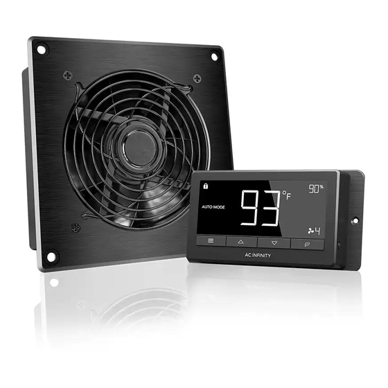
Page 12: Programming
PROGRAMMING 1. MODE BUTTON 2. LEAF BUTTON 3. UP / DOWN BUTTON This button cycles through This turns the display This increases, decreases, each of the controller's off while programs run or adjusts the settings modes settings. Hold for in the background. Hold of the controller for each two seconds to return to for two seconds to lock... - Page 13 PROGRAMMING 1. MODE In this settings mode, you can set the fan’s primary program- ing mode. Remember to return to the main screen after you finished adjusting your settings. ON Mode – Fans will run continuously regardless of temper- ature or humidity. The speed the fans run at will be the speed you have set in (2) Fan Speed.
- Page 14 PROGRAMMING 3. HIGH TEMP. TRIGGER In this settings mode, press the up and down button to set a high temperature trigger. The fans will activate if the probe’s measured temperature exceeds the temperature you have set in this mode. If in SMART Mode, activated fans will slowly increase in speed until it reaches the speed set in (2) Fan Speed;...
- Page 15 PROGRAMMING 5. HIGH HUMIDITY TRIGGER In this settings mode, press the up and down button to set a high humidity trigger. The fans will activate if the probe’s measured humidity exceeds the humidity you have set in this mode. If in SMART Mode, activated fans will slowly increase in speed until it reaches the speed set in (2) Fan Speed;...
- Page 16 PROGRAMMING 7. HIGH TEMPERATURE ALARM In this settings mode, press the up and down button to set a high temperature alarm. The alarm will activate if the probe’s measured temperature exceeds the temperature you have set in this mode. When the alarm triggers, the fan will start spinning at max speed regardless of your other settings.
- Page 17 PROGRAMMING 9. HIGH HUMIDITY ALARM In this settings mode, press the up and down button to set a high humidity alarm. The alarm will activate if the probe’s measured humidity exceeds the humidity you have set in this mode. When the alarm triggers, the fan will start spinning at max speed regardless of your other settings.
- Page 18 PROGRAMMING ALERT ICONS On the bottom right of the display there are four alert icons. They are visible to show that the system’s functions are being monitored. They will flash when the controller wishes to alert you that a particular function is being triggered. FAN FAILURE ALERT The fan failure icon will flash when one or more fans in the AIRTITAN cooling system fails.
- Page 19 PROGRAMMING FAHRENHEIT OR CELSIUS The temperatures displayed can be set to Fahrenheit or Celsius scale by holding up button to change into Fahrenheit and holding down button to change into Celsius. All digits displayed will be automatically converted to the designated scale. DISPLAY BRIGHTNESS To adjust the brightness of the display, please be in the main screen view, then press the up button repeatedly to increase the brightness.
-
Page 20: Other Ac Infinity Products
AC INFINITY PRODUCTS Register Booster Fans The AIRTAP series is a line of register booster fans designed to quietly increase airflow coming from your central heat and air conditioning systems, increasing comfort for your home. Features a thermal controller with intelligent programming that will automatically adjust airflow strength in response to heating and cooling temperatures you have set. -
Page 21: Warranty
This warranty program is our commitment to you, the original purchaser, that each product sold by AC Infinity will be free from defects in manufacturing for a period of two years from the date of purchase. If a product is found to have a defect in material or workmanship, we will take the appropriate actions defined in this warranty to resolve any issues. - Page 22 No part of the materials including graphics or logos available in this booklet may be copied, photocopied, reproduced, translated or reduced to any electronic medium or machine readable form, in whole or in part, without specific permission from AC Infinity Inc.
- Page 24 www.acinfinity.com...
Need help?
Do you have a question about the AIRTITAN SERIES and is the answer not in the manual?
Questions and answers