Table of Contents
Advertisement
Quick Links
QUICK START GUIDE
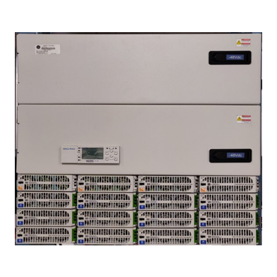
Infinity S (NE-S) -48V Power System
NES48-23-AC1-PS4-DC1E-LVBD
19"/23"
wide
Read and follow all safety statements and precautions in this guide.
Tools required:
Cable Crimpers
Torque wrench (0-240 in-lb / 28 Nm)
Screw Drivers
Screw Drivers (#1 Flat & #2 Phillips)
Step 1 - Mount the System
Mount the system with a minimum gap of 3 inches behind the system to allow proper airflow.
1. Attach the system to the frame using a minimum of twelve (six on each side) 12-24 screws (provided).
Torque to 35 in-lb (7.3 Nm) - 5/16" socket.
Step 2 - Connect Chassis and DC Reference (CO) Ground
1.
Chassis Ground lug - #10 or 1/4" on 5/8" centers (not provided).
Minimum 10 AWG recommended.
Torque to 10-32 screws to 30 in-lb (3.4 Nm) – 5/16" Socket.
2. DC reference ground lug - 5/16" or 3/8" on 1" centers (not provided).
Torque to 160 in-lb.
Note: If connecting chassis ground to frame surface remove non-conductive frame coating and apply
antioxidant for connection.
19" Single Voltage system Without adaptor bus bars
Page 1
© 2020 ABB. All rights reserved.
# of Power
AC input
Slots
AC1 - Molex
AC2 - IEC 3 20 C 19
AC5H - Term Block
AC6 - 3 phase delta Term Block(19"only)
AC7 - 3 phase delta wye Term Block (19" only)
Infinity S - Quick Start Guide
Document CC848908475
# of Distribution
LVBD
Panels
option
5/16," 7/16" and 1/2" nut drivers
Wire cutters and strippers
19" Single Voltage system With adaptor bus bar kit (exploded)
Adaptor bus bar
Advertisement
Table of Contents

Related Manuals for ABB NES48-23-AC1-PS4-DC1E-LVBD


Summary of Contents for ABB NES48-23-AC1-PS4-DC1E-LVBD
- Page 1 19” Single Voltage system Without adaptor bus bars 19” Single Voltage system With adaptor bus bar kit (exploded) Adaptor bus bar Infinity S - Quick Start Guide Page 1 Document CC848908475 © 2020 ABB. All rights reserved.
- Page 2 200-277Vac The rectifier will output 75A in 19" systems with AC5, AC6 or AC7 inputs and in 23" systems with AC5H inputs. All other inputs automatically de-rate the rectifier to 50A output Page 2 © 2020 ABB. All rights reserved.
- Page 3 Two multi-pole adapters are required for each multi-pole breaker - see illustration, right Multi-Pole Adapter Kits - 2 required per breaker CC848756916 850021775 850021955 Poles Lug Landings 1/4” x 5/8” 3/8” x 1” 3/8” x 1” Page 3 © 2020 ABB. All rights reserved.
-
Page 4: Step 7 - Rectifier Installation
4. Correct insertion of the rectifier will automatically add the unit to the controllers’ inventory of units. To remove a rectifier: A. Open latch fully to release and remove. B. Enter Inventory section of controller and remove hardware to clear alarm. Page 4 © 2020 ABB. All rights reserved. -
Page 5: Step 8 - Initial Startup
Battery Monitoring is accomplished with a “Daisy Chained” series of probes connected to J2. The Probes monitor battery temperature and voltage (ES771 required to monitor voltage). Bolt the Probe under the “–“ terminal connector hardware; NOT under the connecting lug. Temperature Measurement Temperature and Voltage Measurement Page 5 © 2020 ABB. All rights reserved. - Page 6 Aux PMJ Input Battery Test/GSTR Battery Test_Return EPO_Return Alarm Input Cables Hi ext. Temp. CC848890153 5 ft. Hi ext. Temp._Return CC848865980 15ft Low ext. Temp. CC848817651 50 ft Low ext. Temp._Return CC848817668 150 ft Page 6 © 2020 ABB. All rights reserved.
- Page 7 Controller Front Panel Display and Controls The main menu can be accessed using the Menu / Enter button The basic menu structure for navigation is shown below Front Panel Menu Structure - Overview Page 7 © 2020 ABB. All rights reserved.
- Page 8 Factory Default password is “Administrator” and should be used for initial logon. It is highly recommended that one of the first activities should be to change the default password(s). Home Page – Web View Page 8 © 2020 ABB. All rights reserved.
-
Page 9: Reference Documents
Insulation rating: 90°C minimum; 105°C (minimum) if internal to enclosed equipment cabinets. Size AC field-wired conductors with 75°C ampacity (NEC) equal to or greater than their panel board circuit breaker rating. Page 9 © 2020 ABB. All rights reserved. - Page 10 Personnel with electronic medical devices need to be aware that proximity to DC power and distribution systems, including batteries and cables, typically found in telecommunications utility rooms, can affect medical electronic devices, such as pacemakers. Effects decrease with distance. Page 10 © 2020 ABB. All rights reserved.
- Page 11 QUICK START GUIDE Change History (excludes grammar & clarifications) Version Date Description of the change 04/07/2021 Updated as per template and added new pictures 10.0 05/26/2022 Corrected labeling in figure on page 1 Page 11 © 2020 ABB. All rights reserved.
- Page 12 – in whole or in parts – is ABB does not accept any responsibility whatsoever forbidden without prior written consent of ABB for potential errors or possible lack of information in this Copyright©...