Table of Contents
Advertisement
Quick Links
TY-WPS1
Model No.
TY-WPS1W
WPS Basic Set
TY-WPSC1
TY-WPSC1W
WPS USB-C Basic Set
TY-WP2B1
TY-WP2B1W
WPS Transmitter Set
Thank you for purchasing the Panasonic product.
• Please read these instructions before operating this product and retain them for future reference.
• Be sure to read "Safety Precautions" (page 2 to 3) before use.
• This Operating Instructions is common to all the models regardless of suffixes of the model number.
No suffix: EU, US
W:
CIS, Oceania, Hong Kong
English
DA0521TS3092 -PB
Operating Instructions
Wireless Presentation System
TY-WPB1
TY-WPB1W
WPS Transmitter
TY-WP2BC1
TY-WP2BC1W
WPS USB-C Transmitter Set
TY-WPBC1
TY-WPBC1W
WPS USB-C Transmitter
Functional Manual
* PressIT is a nickname for "Wireless Presentation System".
For business use
TY-SB01WP
Wireless Presentation
System Receiver Board
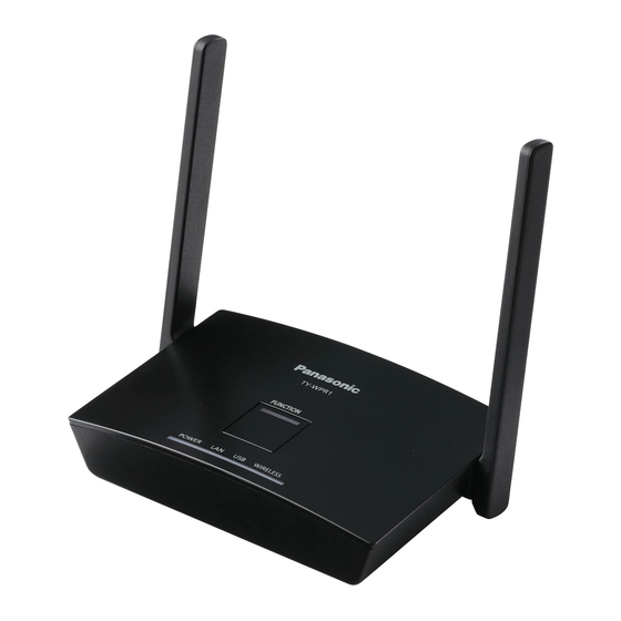
TY-WPR1
WPS Receiver
* WPS is an abbreviation of
"Wireless Presentation System".
DPQP1383ZD/X1
Advertisement
Table of Contents

Related Manuals for Panasonic TY-WPR1


Summary of Contents for Panasonic TY-WPR1
- Page 1 “Wireless Presentation System”. * PressIT is a nickname for “Wireless Presentation System”. Thank you for purchasing the Panasonic product. • Please read these instructions before operating this product and retain them for future reference. • Be sure to read “Safety Precautions” (page 2 to 3) before use.
-
Page 2: Table Of Contents
INDEX Safety Precautions Safety Precautions ........... 2 WARNING: Stop using the product immediately when an Before Using ............. 4 abnormality or malfunction occurs. Features of the system ········································4 Remove the power plug in the case of an Precautions for use ············································4 abnormality. - Page 3 CAUTION: Doing so may cause a fire or electric shock due to short circuit or disconnection. Do not block the vent hole of this product. • Request the dealer for repair of the AC adaptor or Do not push the product into a narrow and poorly power plug.
-
Page 4: Before Using
Before Using Features of the system The wireless presentation system allows screens displayed on an image output device to be projected (mirroring) on a display or projector installed at a remote location. Since small screens of a smartphone, notebook computer, etc. can be displayed on a large screen, this system is convenient to show presentation materials on a large display in a meeting, enjoy images on a large display, show images with a display installed at a location where wiring cables is difficult or other cases. - Page 5 ■ About wired LAN Take sufficient shielding measures at a location where static electricity tends to be generated before using the product. When using the product at locations where lots of static electricity is generated such as carpet, wired LAN communication tends to be disconnected.
-
Page 6: Notes On Using Wireless Lan
Declaration of Conformity (DoC) “Hereby, Panasonic Connect Co., Ltd. declares that this product is in compliance with the essential requirements and other relevant provisions of the Directive 2014/53/EU.” If you want to get a copy of the original DoC of this product, please visit the following website: http://www.ptc.panasonic.de... -
Page 7: Request Regarding Security
● Change your password periodically. ● Panasonic Connect Co., Ltd. or its affiliate companies will never ask for your password directly. Do not divulge your password in case you receive such inquiries. ● The connecting network must be secured by a firewall, etc. -
Page 8: Accessories
Check that you have the accessories and items shown. WPS Basic Set TY-WPS1 / TY-WPS1W WPS Receiver WPS Transmitter Transmitter case (TY-WPR1 / TY-WPR1W) ....1 (TY-WPB1 / TY-WPB1W) ....2 (TY-WPC1) ........1 AC adaptor AC adaptor cable HDMI cable (DPVF3699ZA/X1) .......1 (DPVF3515ZA/X1)......1... -
Page 9: Part Names
HDMI output terminal operate. For information of operable touch modules, see the Connects an imaging device equipped Panasonic information site. When using the BQ1 touch panel with HDMI input. to operate an externally connected device (PC), change the settings of the BQ1 unit. (page 51) These can be used only with one screen display. - Page 10 Part Names Continued ■ Receiver board (TY-SB01WP) Antenna ▼ C onnection terminals / Controls FUNCTION button Used to save a pairing file to the USB memory. LAN terminal (RJ45) Connects to the network to change the settings of the product. USB terminal (Type-A) Connects the transmitter or USB memory when pairing devices.
- Page 11 ■ Transmitter (TY-WPB1 / TY-WPB1W) HDMI input terminal Connect to an imaging device equipped with HDMI output. USB terminal (Type-A) Connect to a USB power supply device. Main button / LED Switches between on and off of image display. Sub button / LED Switches to the multi-screen mode.
-
Page 12: Connection
Connection Before connection, carefully read the operation manual of the device to be connected to this system. Turn off the power of each device before connecting cables. Connecting the receiver Connect the AC adaptor and AC adaptor cable to the receiver for power supply. Use an AC adaptor conversion plug that fits the shape of outlet. -
Page 13: Connecting The Transmitter
Connecting the transmitter Connect the USB terminal and HDMI input terminal of the transmitter to the image output device. • For power supply to the transmitter, 5 V/0.9 A power supply is necessary. USB terminal TY-WPB1 / TY-WPB1W HDMI input terminal TY-WPBC1 / TY-WPBC1W For the USB-C transmitter, connect the USB terminal (Type-C) to the image output device. -
Page 14: Installation Of The Receiver Board
Installation of the receiver board The installation instruction below is based on the flat panel display SQ1 series as an example. For attaching or removing this product to or from the flat panel display unit, it is recommended to ask a qualified technician or sales dealer. - Page 15 Using the screw removed in step 1, fix the receiver board to the SLOT adaptor. Screw ● Tightening torque guideline: 0.5 N·m or less Note ● Firmly tighten the screw, and check that the hook of the SLOT adaptor fixes the circuit board. ●...
- Page 16 Installation of the receiver board Continued Remove the 2 screws, and then remove the slot cover or receiver board from the display unit. To remove the receiver board, hold the handle of the receiver board and pull it out slowly in the arrow direction. Insert the receiver board to the main unit slot, and tighten the 2 screws.
-
Page 17: Basic Use
Basic Use Single connection This section describes how to display an image using one transmitter. Press the main button of the transmitter while the standby screen is displayed. The image is displayed. Standby screen Full screen display White illumination Green illumination (standby) (display) Pressing the main button again changes the main LED to white and returns to standby state. -
Page 18: Multi Connection
Basic Use Continued Multi connection This section describes how to display images simultaneously using multiple transmitters. Images of up to 4 transmitters can be displayed simultaneously. Press and hold the sub button of the transmitter for 1 second or more during full screen display. -
Page 19: Fixing Image Switching (Fixed Mode)
Fixing image switching (fixed mode) When images of 1 transmitter are displayed with multiple transmitters paired and used, you can make a setting that prohibits switching to images of another transmitter. This setting prevents accidental image-switching operation. Setting the fixed mode Press and hold the main button of the transmitter for 1 second or more while an image of one transmitter is displayed. -
Page 20: Transmitter Extension Method (Pairing)
Transmitter Extension Method (Pairing) Pairing settings have been made for transmitter and receiver of TY-WPS1 / TY-WPS1W / TY-WPSC1 / TY-WPSC1W Basic Set. Pairing by connecting the receiver and transmitter Slide the mode switch to the STD side. Connect the USB terminal of the transmitter to the USB terminal of the receiver / receiver board. - Page 21 Pairing by saving a file to the USB memory Supported device ● Commercially available USB memory devices are supported. (Those with security functions are not supported.) ● USB memory devices other than those formatted in FAT16 or FAT32 cannot be used. ●...
-
Page 22: About Lan Connection
■ Wireless LAN connection Using the wireless function of the receiver (TY-WPR1/TY-WPR1W) / receiver board (TY-SB01WP) enable the product to be connected to an external wireless access point or mobile wireless LAN router (only for 5 GHz wireless LAN), and an external network or the Internet. -
Page 23: Using With Android Device (Android 5.0 And Later Versions)
Using with Android device (Android 5.0 and later versions) Using the following two methods allows images on an Android device to (Android 5.0 and later versions supported) be projected (mirroring) on a display or projector. Wireless LAN, security measures, etc. can be used according to the usage environment. - Page 24 Using with Android device (Android 5.0 and later versions) Continued Start up the [PressIT] app. An image with the same design as that of the transmitter is displayed on the Android device. Tap the main button of the transmitter on the screen to display. (The Android OS may provide a notification. Operate the device according to the notification.) Mirroring starts.
-
Page 25: Setting
Setting Connect to the Web page of the receiver to configure the settings of this system. About the standby screen Turn on the receiver to display the standby screen on the display device. Note • For connecting the receiver and display device, see “Connecting the receiver” (page 12). Displays the number of mobile devices connected via wireless LAN of the transmitter or receiver. - Page 26 Setting Continued ■ When connecting for the first time immediately after purchase User ID and password are required when connecting to the Web page of the receiver immediately after purchase or after initialization by pressing the reset button of the receiver. Then, the password needs to be changed. User ID: PressIT_admin Password: Enter the password ( ) displayed on the standby screen.
-
Page 27: Displaying The Web Setting Screen
Displaying the Web setting screen ■ About web browsers We recommend using the web browsers shown below to operate the Web setting screen. Chrome Version 85.0.4183.83 and later versions Firefox Version 80.0.1 and later versions Internet Explorer 11 Safari Version.13.0.5 and later versions Edge Version 84.0.522.52 and later versions ■... - Page 28 Setting Continued ■ When configuring the settings in an environment where wireless LAN (5 GHz band) access point can be used freely Connect the receiver to the external wireless LAN and open the Web setting screen. You can also connect to the external wireless access point different from the wireless access point coming from the receiver to open the Web setting screen.
- Page 29 When the receiver is connected to the external wireless access point, the wireless LAN icon is displayed on the lower right of the standby screen. To store the external wireless access point in the receiver, set [Remember Wireless Access Point] to [On] and click [OK].
-
Page 30: Configuring Various Settings On The Web Setting Screen
Setting Continued Configuring various settings on the Web setting screen Settings including [Device Management], [Network Management] and [Detail Settings] can be changed on the Web setting screen. ■ Download Android APK The Android app (page 23) can be downloaded and installed. Use this app when the device cannot be connected to the Google Play Store. - Page 31 ■ Device Management The Web setting screen has setting options such as Language, Resolution and Max Connection. ● Language Supports major languages including Japanese, German, French and Chinese. The Web setting screen and standby screen are displayed in the selected language. ●...
- Page 32 Setting Continued ● Android audio streaming (Firmware version 1.9598.583 and later) Specifies whether to output the audio of Android from the display device connected to the receiver. On: Enables the function. Off: Disables the function. About [PressIT] app Displays the audio output status using the Android app dedicated to [PressIT].
- Page 33 ● Screen mode Adjusts the size of images. Fit to Screen: Displays images with the aspect ratio of input signals. Stretch to Full Screen: Displays images in full screen. ● Timed Restart Restarts after the time selected on the menu has elapsed when no operation is performed.
- Page 34 Setting Continued ■ Detail Settings This setting function is designed mainly for persons in charge of information system department and network administrators, enabling more detailed setting changes. ● Wireless Channel Sets the Wireless channel. This product provides the following options. Channel Bandwidth * Note that when the receiver is connected to an external wireless access...
- Page 35 Set reboot. Set whether to reboot the device of which the setting has been changed. When changing the settings of multiple devices in succession, select [Cancel]. Note • Reboot is applicable only to the device for which the setting is changed just before the reboot.
- Page 36 Setting Continued ● Password Changes the wireless LAN connection password for the receiver. The administrator can hide the wireless LAN password on the standby screen for security enhancement. Types of characters that can be set: Alphanumeric characters (0 to 9, a to z, A to Z) Number of characters that can be set: 8 to 15 characters Note •...
- Page 37 PIN function When this function is enabled, depending on the mobile terminal to be used, the entry of PIN may be required for connection. If this is the case, enter the 8-digit PIN number displayed at the bottom of the screen.
- Page 38 Setting Continued ● Administrator Password Changes the administrator password. It is recommended to change the administrator password periodically for security enhancement. Types of characters that can be set: Alphanumeric characters (0 to 9, a to z, A to Z) Number of characters that can be set: 6 to 64 characters ●...
- Page 39 ● Upgrade The firmware of the receiver and transmitter can be to the latest versions. This product needs to be stably connected to Internet to upgrade the firmware. It is strongly recommended to use the same firmware version for the receiver and transmitter upgraded of this product.
- Page 40 Setting Continued Pre-setting 2 (pairing) Pair the transmitter to be used with one of the receivers for which “Pre-setting 1” has been completed. Standby screen after the completion of pre-setting Group ID (Cast Group set as above) and “Mode: Multicast” are displayed at the bottom. Since the Multi-screen mode is not supported, the operation guide display is changed.
- Page 41 ● Background Color setting Specifies the background colors for the standby screen and no-signal image. [Black] or [Blue] can be specified. Note • When the [My Screen] is specified, this setting is not reflected. ● Date/Time setting Specifies the time zone and the display style of date displayed on the standby screen.
- Page 42 Setting Continued ● Reset to Factory Default Initializes this product to the default state. Note that the customized language setting, resolution setting, wireless LAN setting, etc. once stored are initialized. (SSID is not initialized.) When the transmitter is initialized, the paired state between the receiver and transmitter is canceled.
-
Page 43: [Setup] Menu (Display Setting)
Sets EDID compatible with 2K video signals (Max. 1 920 x 1 200 dots). Note • This function is explained using the Panasonic display SQ1 series as an example. Depending on the model, the setting items differ. • When EDID is set to [4K/60p/SDR] or [4K/60p/HDR], images of 4K/30p are output. - Page 44 Panasonic display link function Just connect the receiver to a Panasonic display supporting this product using HDMI cable and turn them on to perform the link operation. (It is necessary to set [Wireless presentation link] to [On].) Set link function details in the following setting menus.
- Page 45 ■ External device link settings Sets external device link. [External device link settings]- submenu screen External device link settings Device information Wireless presentation link ● [Device information] Sets whether to display or hide the information of the device connected to the HDMI terminal. [Off]: Connected device information is not displayed.
- Page 46 Setting Continued ■ [Wireless presentation settings] Note • Approx. 5 seconds may be required to reflect the menu settings. [Wireless presentation settings] - sub menu screen Wireless presentation settings Background colour setting Black Date/Time setting Y/M/D Language link Enable ● [Background colour setting] [Black]: The background color for the standby screen and no-signal image is set to black.
- Page 47 ■ HDMI-CEC settings Set for HDMI-CEC function. For details of HDMI-CEC function, refer to “Using the HDMI-CEC function”. (see page 48) [HDMI-CEC settings] - submenu screen HDMI-CEC settings HDMI-CEC control Enable HDMI1 ---- HDMI2 ---- SLOT ---- HDMI-CEC operation MENU code Link function Display → Device Disable...
-
Page 48: Using The Hdmi-Cec Function
Setting Continued Using the HDMI-CEC function The HDMI-CEC function allows the display to be turned on/off or the input to be switched by linking the operation of this product. ■ CEC-ON link The display is turned on (image-receiving state) when it is turned off (standby state). The image of this product is projected by switching to the input to which this product is connected. - Page 49 (3) When the image from the transmitter is displayed in standby state When the transmitter is in standby state, press the main button to send the image to the receiver. Then the display is turned on and the image is displayed. The input of the display is linked to the operation of the transmitter and switched to the input to which the receiver is connected.
- Page 50 Setting Continued ■ CEC-OFF link Performing the following 2 operations allows the display to be turned off (standby state). (1) When the screensaver is activated When the screensaver of this product is activated while the transmitter is in standby state, the display is turned off. Standby screen Display power off (standby) After the specified time...
-
Page 51: Using "Hdvc" On This System
Using “HDVC” on this system When using an HDCP-incompatible device including the PC sharing function of Panasonic video conference system “HDVC” with this system, perform the operation on the back side. Press and hold the FUNCTION button When the LED lights in red, release of the receiver for 10 seconds or more. -
Page 52: Installing The Receiver Installing The Receiver
Installing the Receiver Components for receiver mounting bracket Check the following parts are included. Base bracket (A-1) ......1 Connecting bracket C (A-4) ..1 Knurled screw (C-1)......2 (DPVF3503ZA/X1) (DPVF3506ZA/X1) (DPVF3509ZA/X) Used to install on the projector. (M4×5) Connecting bracket A (A-2) ..1 Sheet A (B-1) .........1 Screw (C-2) ........6 (DPVF3505ZA/X1) -
Page 53: Installing On The Ceiling Or Wall
Installing on the ceiling or wall Mount the base bracket (A-1) to the receiver. Fix the receiver to the ceiling or wall with 2 screws. Use screws (commercially available) of the appropriate type and length according to the ceiling or wall to be installed. - Page 54 Installing the Receiver Continued Attach 1 sheet A (B-1) and 3 sheets B (B-2) to the brackets along the marking-off lines Remove the double-sided taped release paper from those sheets and attach them to the brackets. Then remove the protection films. Protection film Release paper Install the receiver on the display.
-
Page 55: Recommended Example For Installing On The Projector Professional Model
Recommended example for installing on the projector professional model Mount the base bracket (A-1) to the receiver. Remove 2 round covers from the side of the projector. Screw holes for installing the receiver are exposed. Cover Install the receiver on the projector with 2 screws (C-3). Install the receiver with marking “UP”... -
Page 56: Recommended Example For Installing On The Projector System Model
Installing the Receiver Continued Recommended example for installing on the projector system model Mount the base bracket (A-1) to the receiver. Fix the connecting bracket C (A-4) to the base bracket (A-1) with 2 screws (C-2). Remove the adjuster on the bottom surface of the projector by turning it counterclockwise. - Page 57 When installing the receiver to the models shown below, mount it at specified positions for safety. ● PT-FRZ60 series (PT-FRZ60 / PT-FRZ50 / PT-FRZ55) ● PT-RZ570 series (PT-RZ570 / PT-RZ575) Setting on a desk or floor Mounting on a ceiling ●...
-
Page 58: Portable Model
Installing the Receiver Continued Recommended example for installing on the projector portable model Use a commercially sold fixing band with a width of 25 mm or less. Mount the base bracket (A-1) to the receiver. Attach 2 sheets B (B-2) to the bracket along the marking-off lines Remove the double-sided taped release paper from those sheets and attach them to the brackets. -
Page 59: Image Signals Supported By This Product
Image Signals Supported by This Product ■ Image output resolution of the receiver WPS Receiver (TY-WPR1 / TY-WPR1W) WPS Receiver board (TY-SB01WP) HDMI output signals 3840 x 2160@30Hz RGB 1920 x 1080@24Hz 1920 x 1080@60Hz RGB 1280 x 1024@60Hz 4096 x 2160@24Hz... -
Page 60: Troubleshooting
Troubleshooting Symptoms Checks Page ● Pairing does not start by connecting the transmitter Is the mode switch of the transmitter on the STD to the USB terminal of the receiver. side? ● Pairing does not start by connecting the USB Is the mode switch of the transmitter on the EXT memory where the pairing file is stored to the USB side? -
Page 61: Specifications
Specifications ■ Receiver Model No. TY-WPR1 / TY-WPR1W Product name WPS Receiver Video output HDMI × 1 (HDCP1.4) Output resolution 1920 x 1080/60p, 3840 x 2160/30p (max.) Number of simultaneous connections Wireless communication IEEE802.11a/n/ac standard Bluetooth (GFSK, π/4-DQPSK, 8DPSK) Data rate wireless 867 Mbps (max.) Frequency band 5 GHz (5.150 GHz to 5.250 GHz) - Page 62 Specifications Continued ■ Transmitter Model No. TY-WPB1 / TY-WPB1W TY-WPBC1 / TY-WPBC1W Product name WPS Transmitter WPS USB-C Transmitter USB Type-C × 1 Video input HDMI × 1 (HDCP1.4) (HDCP1.4, DisplayPort Alt Mode) Input resolution 1920 x 1080/60p (max.) Wireless communication IEEE802.11ac standard Data rate wireless...
-
Page 63: Software License
Web setting screen of this product. At least three (3) years from delivery of this product, Panasonic Connect Co., Ltd. will give to any third party who contacts us at the contact information provided below, for a charge no more than our cost of physically performing source code distribution, a complete machine-readable copy of the corresponding source code covered under GPL V2.0, LGPL V2.0, LGPL V2.1 or the other licenses with the obligation to do so, as well as the respective copyright... -
Page 64: Fcc Statement
FCC CAUTION: To assure continued compliance, follow the attached installation instructions and use only the provided power supply cord. Any changes or modifications not expressly approved by Panasonic Corp. of North America could void the user’s authority to operate this device. - Page 65 Warranty Service purposes. Model Number Serial Number Panasonic Connect North America Unit of Panasonic Corporation of North America Executive Office : Two Riverfront Plaza, Newark, New Jersey 07102 Authorized Representative in EU:...