Siemens SIMATIC Ident Function Manual
Hide thumbs
Also See for SIMATIC Ident:
- System manual (362 pages) ,
- Function manual (142 pages) ,
- Operating manual (80 pages)
Table of Contents
Advertisement
Quick Links
SIMATIC Ident
RFID systems
Ident profile, Add-on instruction
for Rockwell systems
Function Manual
07/2020
C79000-G8976-C410-04
Preface
Introduction
Description
Configuring with Studio
5000 Logix Designer
Configuring the
instructions
Diagnostics and error
messages
Appendix
Service & Support
1
2
3
4
5
A
B
Advertisement
Table of Contents

Related Manuals for Siemens SIMATIC Ident


Summary of Contents for Siemens SIMATIC Ident
- Page 1 Preface Introduction SIMATIC Ident Description Configuring with Studio 5000 Logix Designer RFID systems Ident profile, Add-on instruction Configuring the for Rockwell systems instructions Diagnostics and error messages Function Manual Appendix Service & Support 07/2020 C79000-G8976-C410-04...
- Page 2 Note the following: WARNING Siemens products may only be used for the applications described in the catalog and in the relevant technical documentation. If products and components from other manufacturers are used, these must be recommended or approved by Siemens. Proper transport, storage, installation, assembly, commissioning, operation and maintenance are required to ensure that the products operate safely and without any problems.
-
Page 3: Preface
If there are any deviations between the recommendations provided in these application examples and other Siemens publications – e.g. Catalogs – the contents of the other documents have priority. - Page 4 Preface Ident profile, Add-on instruction for Rockwell systems Function Manual, 07/2020, C79000-G8976-C410-04...
-
Page 5: Table Of Contents
Table of contents Preface .................................3 Introduction ..............................7 Description ..............................9 Area of application and features ..................... 9 Functions of the instructions ......................9 Configuring with Studio 5000 Logix Designer ..................11 Configuring with Studio 5000 Logix Designer ................11 Integrating modules into Studio 5000 Logix Designer ............. 11 Creating a Studio 5000 Logix Designer project ................. - Page 6 Table of contents 4.5.3.6 Read_UID ............................47 4.5.3.7 Set_Ant..............................48 4.5.3.8 Set_Param ............................49 4.5.3.9 Write_EPC_ID ............................ 52 4.5.3.10 Write_EPC_Mem ..........................53 4.5.4 Status instructions ........................... 54 4.5.4.1 Reader_Status ........................... 54 4.5.4.2 Tag_Status ............................57 4.5.5 RESET instructions ........................... 60 4.5.5.1 Reset_Reader ............................
-
Page 7: Introduction
RF186CI/RF188CI and the communication module RFID 181EIP. Documentation classification You can find additional information on the blocks and Ident devices named in this manual on the Siemens Industry Online Support (https://support.industry.siemens.com/cs/ww/en/ps/14971/man) pages or on the DVD "Ident Systems" (6GT2080-2AA20) in the respective manuals: •... - Page 8 Link: (https://www.siemens.com/industrialsecurity) Siemens’ products and solutions undergo continuous development to make them more secure. Siemens strongly recommends that product updates are applied as soon as they are available and that the latest product versions are used. Use of product versions that are no longer supported, and failure to apply the latest updates may increase customers’...
-
Page 9: Description
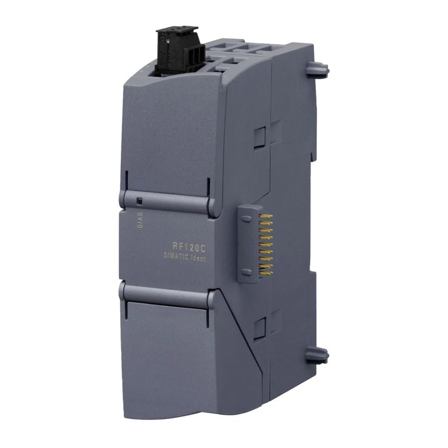
Description Area of application and features The Ident profile can be used in Rockwell controllers with an Ethernet/IP interface. The modules can be configured using the "Studio 5000 Logix Designer" or "RSLogix 5000" programs. Figure 2-1 Configurable module: RF18xC/RF18xCI, RFID 181EIP and RF61xR/RF68xR Functions of the instructions The "Ident_Profile"... - Page 10 Description 2.2 Functions of the instructions Ident profile, Add-on instruction for Rockwell systems Function Manual, 07/2020, C79000-G8976-C410-04...
-
Page 11: Configuring With Studio 5000 Logix Designer
The modules must be integrated into the Studio 5000 Logix Designer via an EDS file. The EDS file is contained in the Add-On Instructions library. You can find the latest file on the pages of the Siemens Industry Online Support (https://support.industry.siemens.com/cs/ww/en/ps/14971/dl). For the RF600 readers and the RF18xC/RF18xCI communication modules, the EDS file can be downloaded via the WBM of the modules ("System >... -
Page 12: Creating A Studio 5000 Logix Designer Project
Configuring with Studio 5000 Logix Designer 3.3 Creating a Studio 5000 Logix Designer project Creating a Studio 5000 Logix Designer project The modules can be integrated into Rockwell automation systems using Studio 5000 Logix Designer. The connection is via Ethernet/IP. Following this, you can configure the RF600 reader using WBM while you control the work with the module using the add-on instructions of Studio 5000 Logix Designer. -
Page 13: Configuring The Instructions
To program Ident systems using the Studio 5000 Logix Designer, you require add-on instructions. You can find the add-on instructions on the DVD supplied with the RF600 readers or on the pages of the Siemens Industry Online Support (https://support.industry.siemens.com/cs/ww/en/ps/14971/dl). Requirement The Studio 5000 Logix Designer was started and a project was created. -
Page 14: Overview Of The Add-On Instructions
Configuring the instructions 4.2 Overview of the add-on instructions Overview of the add-on instructions To program the various identification systems, a library with add-on instructions is available. The following table provides an overview of the currently available add-on instructions. Table 4- 1 Overview of the add-on instructions Position Symbolic name... - Page 15 Configuring the instructions 4.2 Overview of the add-on instructions Position Symbolic name Description Data types System data types IID_CMD_STRUCT Data type for the Ident profile for setting the command parameters. IID_DATA_RF600 Data type for parameter data for the reader / communication module and data for synchroniz- IID_DATA_RF18XC ing the instructions for all read points of a reader.
-
Page 16: General Structure Of The Instructions
Configuring the instructions 4.3 General structure of the instructions General structure of the instructions Form of the instruction as an example The following graphic shows an example of a instruction with input and output parameters as they exist in the same way in all instructions. Figure 4-1 Example instructions Description of the parameters... -
Page 17: Project Preparation
Configuring the instructions 4.4 Project preparation Parameter Description Output parameters DONE (BOOL) The job was executed. If the result is positive, this parameter is set. BUSY (BOOL) The job is being executed. ERROR (BOOL) The job was ended with an error. The error code is indicated in Status. -
Page 18: Creating A Message Variable
Configuring the instructions 4.4 Project preparation instruction have a "HW_CONNECT" parameter where the respective "HW_CONNECT" variable must be created for the corresponding channel. 4.4.2 Creating a message variable A message variable must be created for each module. The parameter assignment is transferred with the aid of this variable and this is required for the "MSG_PARAM"... -
Page 19: Configuring A Message Variable For Receiving A Channel
Configuring the instructions 4.4 Project preparation 4.4.2.2 Configuring a message variable for receiving a channel This message variable must be created and configured for each channel of a module. Ensure you select the correct buffer when setting the "Source Element" and "Destination Element"... -
Page 20: Configuring A Message Variable For Sending A Channel
Configuring the instructions 4.4 Project preparation 4.4.2.3 Configuring a message variable for sending a channel This message variable must be created and configured for each channel of a module. Ensure you select the correct buffer when setting the "Source Element" and "Destination Element"... - Page 21 Configuring the instructions 4.4 Project preparation Each of these channels can be configured independently. The following basic parameters are available: • General reader for RF300, RF200 and MV400/MV500 • RF300 fast protocol for RF300 (Gen2) • Freeport Parameter values of the "IID_PARAMETER_RF18XC" parameter variable Table 4- 6 Basic parameters of the variables Name...
- Page 22 Configuring the instructions 4.4 Project preparation Table 4- 7 Sub-parameters of the "ReaderSlot" parameters Name Value Meaning Description ModuleID 16#2001 0002 General reader Selection of the desired Ident sys- tem (ID of the module) 16#2001 1002 RF300 fast protocol 16#2000 8002 Freeport BaudRate 16#01...
- Page 23 Configuring the instructions 4.4 Project preparation Name Value Meaning Description that indicate the end of a character. The stop bits are appended to every transferred character during trans- mission. Interface RS422 Selection of the interface type that the connected hardware (reader / RS232 optical readers) uses.
- Page 24 Configuring the instructions 4.4 Project preparation Name Value Meaning Description FirstEndDelime- 16#00 ... 16#FF Requirement: "EndDetection = 1" Entry of the first end delimiter of a maximum of two end delimiters for the end criteria "On receipt of the end delimiter(s)". The selected end delimiter or the selected end delim- iter combination limits the length of the frame.
-
Page 25: Executing The Parameter Instruction
Configuring the instructions 4.4 Project preparation 4.4.4 Executing the parameter instruction To establish an initial connection between the Ident device and the controller, a parameter instruction must be executed after each restart of the Ident device or the controller. This transfers the required parameter data to the Ident device and the values for the "HW_Connect"... -
Page 26: Executing The Reset Command
Configuring the instructions 4.4 Project preparation 4.4.5 Executing the reset command A reset command must be executed for each channel of a communication module or for each reading point of an RF600 reader after the variables have been created and before the actual work with the Ident instructions. - Page 27 Configuring the instructions 4.4 Project preparation 7. Select the relevant output word of the reader/CM for the "CONTROL_WORD" parameter. You can find detailed information on this in the section "Assignment table (Page 28)". 8. Supply the instruction-specific reset parameters (e.g. "TAG_TYPE" for "Reset_RF300") You can find detailed information on this in the section "RESET instructions (Page 60)".
-
Page 28: Assignment Table
Configuring the instructions 4.4 Project preparation 4.4.6 Assignment table In order to be able to use the Ident instructions, the "HW_CONNECT", "STATUS_WORD" and "CONTROL_WORD" parameters must be supplied for the respective channel or for the reading point. The assignment of these parameters is described in the following table: Table 4- 10 Parameter assignment for the parameters "HW_CONNECT", "STATUS_WORD"... -
Page 29: Programming Instructions
Configuring the instructions 4.5 Programming instructions Programming instructions 4.5.1 Parameter instructions The configuration data is sent to the Ident system using the "Param_RF600", "Param_RF18xC" or "Param_RFID181EIP" instruction. In addition to this, the instruction resets the required start values of the "HW_CONNECT" variables for the reader channels (read points). - Page 30 Configuring the instructions 4.5 Programming instructions Table 4- 11 Explanation for the instruction "Param_RF600" Parameter Data type Default values Description LARGE_ BOOL With this variable, the telegram CONNECTION length of the Ethernet/IP telegrams can be changed: • 240 bytes = false (default) •...
-
Page 31: Param_Rf18Xc
Configuring the instructions 4.5 Programming instructions 4.5.1.2 Param_RF18xC You can use the "Param_RF18xC" instruction to transfer the configuration data to an RF18xC/RF18xCI communication module. Figure 4-3 "Param_RF18xC" instruction Table 4- 12 Explanation for the instruction "Param_RF18xC" Parameter Data type Default values Description DEVICE_ IID_PARAMETER_... -
Page 32: Param_Rfid181Eip
Configuring the instructions 4.5 Programming instructions 4.5.1.3 Param_RFID181EIP The "Param_RFID181EIP" instruction can be used to transfer the configuration data to an RFID181 EIP communication module. Figure 4-4 Instruction "Param_RFID181EIP" Table 4- 13 Explanation for the instruction "Param_RFID181EIP" Parameter Data type Default values Description MOBY_MODE... -
Page 33: Basic Instructions
Configuring the instructions 4.5 Programming instructions 4.5.2 Basic instructions 4.5.2.1 Read The "Read" instruction reads the user data from the transponder and enters this in the "IDENT_DATA" buffer. The physical address and the length of the data are transferred using the "ADDR_TAG" and "LEN_DATA" parameters. With the RF600 readers, the instruction reads the data from memory bank 3 (USER area). -
Page 34: Write
Configuring the instructions 4.5 Programming instructions Parameter Data type Default values Description EPCID_UID SINT[62] Buffer for up to 62 bytes EPC-ID, 8 bytes UID or 4 bytes handle ID. • 2 - 62-byte EPC-ID is entered at the start of the buffer (length is set by "LEN_ID") •... - Page 35 Configuring the instructions 4.5 Programming instructions Table 4- 15 Explanation for the instruction "Write" Parameter Data type Default values Description ADDR_TAG DINT 0x00 Physical address on the transponder where the write starts. You will find more information on addressing in the section "Transponder addressing (Page 98)".
-
Page 36: Read_Mv
Configuring the instructions 4.5 Programming instructions 4.5.2.3 Read_MV The "Read_MV" instruction reads the read result of an optical reader. The "Read" instruction must be used to read the configuration. The length of the data to be read is calculated automatically by the instruction based on the length of the created receive buffer. -
Page 37: Set_Mv_Program
Configuring the instructions 4.5 Programming instructions 4.5.2.4 Set_MV_Program Using the "Set_MV_Program" instruction, you can change the program in a camera. The required program number is transferred using the "PROGRAM" parameter. Figure 4-8 Instruction "Set_MV_Program" Table 4- 17 Explanation for the instruction "Set_MV_Program" Parameter Data type Default values... - Page 38 Configuring the instructions 4.5 Programming instructions Figure 4-9 Instruction "AdvancedCMD" Table 4- 18 Explanation for the instruction "AdvancedCMD" Parameter Data type Default values Description CMDSEL Selection of the command to be executed "CMDREF"; 1 ⇒ 1. Command, ... The value of the "CMDSEL" parame- ter can never be >...
-
Page 39: Config_Upload/-_Download
Configuring the instructions 4.5 Programming instructions 4.5.3.2 Config_Upload/-_Download Using the "Config_Upload" and "Config_Download" instructions, you can read ("Config_Upload") or write ("Config_Download") the configuration of the RFID181 EIP reader and RF600 reader communications modules connected to this controller. The configuration data is not interpretable data. Save the data on the controller so that it can be written to the reader again if a device is replaced. - Page 40 Configuring the instructions 4.5 Programming instructions Figure 4-10 Instruction "Config_Upload" Table 4- 20 Explanation for the instruction "Config_upload" Parameter Data type Default value Description IDENT_DATA SINT[10] Data buffer for configuration data. The real length of the data depends on the complexity of the configura- tion and the firmware version of the reader.
-
Page 41: Inventory
Configuring the instructions 4.5 Programming instructions Figure 4-11 Instruction "Config_download" Table 4- 21 Explanation for the instruction "Config_download" Parameter Data type Default value Description IDENT_DATA SINT[10] Data buffer for configuration data. The real length of the data depends on the complexity of the configura- tion and the firmware version of the reader. - Page 42 Configuring the instructions 4.5 Programming instructions There are four different modes that you can select with the "ATTRIBUTE" parameter. • At the start, a certain duration/number (period of time, number of inventories, number of "Observed" events or identified transponders) is specified. A distinction is made between the following options: –...
- Page 43 Configuring the instructions 4.5 Programming instructions Figure 4-12 Instruction "Inventory" Table 4- 22 Explanation for the instruction "Inventory" Parameter Data type Default values Description ATTRIBUTE SINT 0x00 Selecting the status mode: • RF600: 0x80, 0x81, 0x86, 0x87 DURATION 0x00 Duration dependent on "DUR_UNIT" Period of time or number of invento- ries or number of "Observed"...
- Page 44 Configuring the instructions 4.5 Programming instructions Results for RF600 The number of "TAG_DATA[x]" elements of the data types of the ATTRIBUTE "0x80" and "0x81" depends on the number of transponders to be expected. For this reason, you need to assemble the receive buffer yourself. Not the following structure when creating the receive buffer "IDENT_DATA"/data type: •...
-
Page 45: Read_Epc_Mem
Configuring the instructions 4.5 Programming instructions Name Type Comment time DINT timestamp power SINT power in dBm filterDataAvailable SINT 0=false; 1=true Inventoried TAG_DATA[2] IID_IN_1_81 TAG_DATA[n] IID_IN_1_81 Indicates how often the transponder was identified via the air interface before it changed to the "Observed" status. 4.5.3.4 Read_EPC_Mem The "Read_EPC_Mem"... -
Page 46: Read_Tid
Configuring the instructions 4.5 Programming instructions Table 4- 25 Explanation for the instruction "Read_EPC_Mem" Parameter Data type Default values Description LEN_DATA 0x00 Length of the EPC memory to be read out (1 ... 62 bytes) Default value: 0x00 ≙ unspecified LEN_ID SINT 0x00... -
Page 47: Read_Uid
Configuring the instructions 4.5 Programming instructions Table 4- 26 Explanation for the instruction "Read_TID" Parameter Data type Default values Description LEN_DATA 0x00 Length of the TID memory to be read Default value: 0x00 ≙ unspecified LEN_ID SINT 0x00 Length of the EPC-ID/UID single tag access (RF600) EPCID_UID SINT[62]... -
Page 48: Set_Ant
Configuring the instructions 4.5 Programming instructions 4.5.3.7 Set_Ant Using the "Set_Ant" instruction, you can switch antennas on or off. The "Set_Ant_RF300" instruction can also be used for RF200. Set_Ant_RF300 Figure 4-16 Instruction "Set_Ant_RF300" Table 4- 28 Explanation for the instruction "Set_Ant_RF300" Parameter Data type Default values... -
Page 49: Set_Param
Configuring the instructions 4.5 Programming instructions 4.5.3.8 Set_Param Using the "Set_Param" instruction, you can change UHF parameters (e.g. the antenna power) on an RF61xR/RF68xR, as well as the date/time parameters of an RF18xC/RF18xCI during runtime. Note that changes to the date/time parameters of an RF18xC/RF18xCI can only be made via the "CM_Configuration"... - Page 50 Configuring the instructions 4.5 Programming instructions Values for "PARMID" and "VALUE" Depending on the Ident device used, the following parameters can be read out with the aid of this block. Table 4- 30 Parameter values PARMID PARMID Parameter VALUE (hex) (ASCII) 0x41315057 A1PW...
- Page 51 Configuring the instructions 4.5 Programming instructions PARMID PARMID Parameter VALUE (hex) (ASCII) 0x52364353 R6CS Modulation scheme Range of values: 32, 33, 34, 35, 37, 65 Modulation scheme of the read point Specification of which transpond- er types are identified (ISO 18000-63/-62).
-
Page 52: Write_Epc_Id
Configuring the instructions 4.5 Programming instructions 4.5.3.9 Write_EPC_ID The "Write_EPC_ID" instruction overwrites the EPC-ID of the RF600 transponder and adapts the length of the EPC-ID in the memory of the transponder. The new EPC-ID length to be written is specified with the "LEN_ID_NEW" parameter and the previous EPC-ID is specified using the "LEN_ID"... -
Page 53: Write_Epc_Mem
Configuring the instructions 4.5 Programming instructions 4.5.3.10 Write_EPC_Mem The "Write_EPC_Mem" instruction overwrites the EPC memory of the RF600 transponder starting at address 4. The length of the EPC memory to be overwritten is specified by the "LEN_DATA" parameter. Figure 4-19 Instruction "Write_EPC_Mem" Table 4- 32 Explanation for the instruction "Write_EPC_Mem"... -
Page 54: Status Instructions
Configuring the instructions 4.5 Programming instructions 4.5.4 Status instructions 4.5.4.1 Reader_Status The "Reader_Status" instruction reads status information from the reader or communication module (RF18xC/RF18xCI with the "CM configuration_1" module). For the various reader families, there are different status modes that you can select using the "ATTRIBUTE"... - Page 55 Configuring the instructions 4.5 Programming instructions Results Apply the correct data type that is assigned to the ATTRIBUTE value at the "IDENT_DATA" input of the instruction so that the data can be correctly interpreted. Only an Array of Byte can be created at the "Ident Data" parameter . The conversion to the corresponding data type must be done manually.
- Page 56 Configuring the instructions 4.5 Programming instructions Table 4- 36 ATTRIBUTE "0x6F" (data type "IID_READSTAT_EF_RF300G2") Name Type Comment status info SINT Reader status mode hardware SINT Type of hardware hardware_version Version of hardware 0 = RF310R, RF340R, RF350R; 1 = RF380R, RF260R; 2 = RF310R (ISO), RF210R, RF220R;...
-
Page 57: Tag_Status
Configuring the instructions 4.5 Programming instructions Name Type Comment reader_type SINT Type of connected reader 0 = RF310R, RF340R, RF350R; 1 = RF380R, RF260R; 2 = RF310R (ISO), RF210R, RF220R; 3 = RF380R (ISO), RF240R; 4 = RF340R (ISO), RF350R (ISO), RF250R; 5 = RF310R (ISO);... - Page 58 Configuring the instructions 4.5 Programming instructions Table 4- 39 Explanation for the instruction "Tag_Status" Parameter Data type Default values Description ATTRIBUTE SINT 0x00 Identifier of the status modes / pos- sible entries: • RF200: 0x83 • RF300: 0x04, 0x82, 0x83 Default value: 0x00 ≙...
- Page 59 Configuring the instructions 4.5 Programming instructions Table 4- 41 ATTRIBUTE "0x82" ("IID_TAG_STATUS_82_RF300" data type) Name Type Comment reserved SINT status info SINT Tag status mode SINT[8] SINT Magnetic flux density: correlation between limit- value SINT Error counter passive: distortion without commu- nication SINT Error counter active: distortion during communi-...
-
Page 60: Reset Instructions
Configuring the instructions 4.5 Programming instructions 4.5.5 RESET instructions The reset instructions described in this section are required if you want to operate the modules with a Rockwell controller. Remember that the default value will be used automatically if you do not select a value manually. -
Page 61: Reset_Rf200
Configuring the instructions 4.5 Programming instructions Table 4- 43 Explanation for the instruction "Reset_MV" Parameter Data type Default values Description PROGRAM SINT Program selection • B#16#0: Reset without program selection or in the case of diag- nostics, the error code for "IN_OP = 0"... -
Page 62: Reset_Rf300
Configuring the instructions 4.5 Programming instructions 4.5.5.4 Reset_RF300 Figure 4-25 Instruction "Reset_RF300" Table 4- 45 Explanation for the instruction "preset_RF300" Parameter Data type Default values Description TAG_CONTROL SINT Presence check • 0 = Off • 1 = on • 4 = presence (antenna is off. The antenna is turned on only when a Read or Write command is sent.) TAG_TYPE... -
Page 63: Reset_Univ
Configuring the instructions 4.5 Programming instructions 4.5.5.5 Reset_Univ The "Reset_Univ" instruction is a universal reset statement that can be used to reset identification systems. Figure 4-26 Instruction "RESET_Univ" Table 4- 46 Explanation for the instruction "RESET_Univ" Parameter Data type Default values Description PARAM SINT [16]... -
Page 64: Programming The Ident Profile
Configuring the instructions 4.6 Programming the Ident profile Programming the Ident profile 4.6.1 Structure of the Ident profile Note Parallel operation using Ident instructions and Ident profile is not possible Note that the CM or reader cannot be operated at the same time using the Ident instructions and the Ident profile. - Page 65 Configuring the instructions 4.6 Programming the Ident profile Figure 4-27 The input parameters of the Ident profile Note Working with multiple channels If you work with several channels, you must ensure that for each channel, the instruction is called with a separate instance DB. Ident profile, Add-on instruction for Rockwell systems Function Manual, 07/2020, C79000-G8976-C410-04...
- Page 66 Configuring the instructions 4.6 Programming the Ident profile Interface description Table 4- 48 Input parameter Input parameter Data type Default value Meaning HW_CONNECT HW_CONNECT Global parameter of type "IID_HW_CONNECT" to address the communication module and reader and to synchronize the instructions. This parameter is located in the varia- bles of the type "IID_DATA_ *".
- Page 67 Configuring the instructions 4.6 Programming the Ident profile Table 4- 49 Output parameter Output parameter Data type Default value Meaning DONE BOOL FALSE TRUE = Command was executed free of errors. ERROR BOOL FALSE TRUE = Error was detected. The error is output in the "STATUS" parameter. The bit is reset automatically when a new command is started.
-
Page 68: Assigning Parameters For The Instruction
Configuring the instructions 4.6 Programming the Ident profile Output parameter Data type Default value Meaning UIN0 BOOL FALSE With RFID readers, the number of transponders in the antenna field is indicated. UIN0 ... UIN3 can be interpret- UIN1 BOOL FALSE ed as binary values. - Page 69 Configuring the instructions 4.6 Programming the Ident profile • MSG_READ • MSG_WRITE • STATUS_WORD • CONTROL_WORD Example of parameter assignment Ident_Profile Create a instance variable. CMDREF Assign a variable to the "CMDREF" parameter. This variable has the "IID_CMD_STRUCT[10]" data type. HW_CONNECT Assign a variable to the "HW_CONNECT"...
-
Page 70: Data Structure Of The Ident Profile
Configuring the instructions 4.6 Programming the Ident profile The element numbers are assigned as follows: • Element 0 for channel 1: ...Data[0] • Element 1 for channel 2: ...Data[1] Figure 4-29 Automatically created input and output variables MSG_WRITE and MSG_READ Assign a "MESSAGE"... - Page 71 Configuring the instructions 4.6 Programming the Ident profile Figure 4-30 Data structure example of the Ident profile Ident profile, Add-on instruction for Rockwell systems Function Manual, 07/2020, C79000-G8976-C410-04...
-
Page 72: Commands Of The Ident Profile
Configuring the instructions 4.6 Programming the Ident profile Explanation of the data structure example • CMDREF[0]: Command "WRITE-CONFIG", OFFSETBUFFER = 0 At the "CMDREF[0]" point you need to set the "WRITE-CONFIG" command so that the "INIT/Reset" is correctly executed. • CMDREF[1]: Command "WRITE", OFFSETBUFFER = 15 •... - Page 73 Configuring the instructions 4.6 Programming the Ident profile Command Command code Parameters used Description ASCII 0x65 OFFSETBUFFER, Transfers further commands not specified in the EPCID_UID, LEN_ID, standard profile. To this end, a corresponding LEN_DATA data structure is defined in the send data buffer for each command.
-
Page 74: Command Structure
Configuring the instructions 4.6 Programming the Ident profile 4.6.4.2 Command structure Before you can start a command with "EXECUTE" or "INIT", you need to define the command. To allow simple definition of a command, the command buffer "CMDREF" was created using the "IID_CMD_STRUCT" data type. In the command buffer, you have 10 areas available in which commands can be programmed. - Page 75 Configuring the instructions 4.6 Programming the Ident profile Parameter Data type Default Description value EXT_UHF STRUCT Structure for additional parameters LEN_ID SINT Length of the valid data in the "EPCID_UID" field. MEM_BANK SINT Memory bank on the transponder • 0x00 = RESERVED •...
-
Page 76: Commands
Configuring the instructions 4.6 Programming the Ident profile 4.6.4.3 Commands All relevant parameters and parameter values for the individual commands are listed below. Parameters that are not listed receive the default value specified in the previous section. Table 4- 52 PHYSICAL-READ Parameter Value / description 0x70... - Page 77 Configuring the instructions 4.6 Programming the Ident profile Parameter Value / description 0x00 ≙ unspecified single tag access LEN_ID Length of the EPC-ID (2-62 bytes) 0x00 ≙ Reserved MEM_BANK Memory bank 0x01 ≙ EPC • 0x02 ≙ TID • 0x03 ≙ USER •...
- Page 78 Configuring the instructions 4.6 Programming the Ident profile Parameter Value / description LEN_ID Length of the EPC-ID/UID RXREF Received status data You will find the data structure of the status modes in the section "Tag_Status (Page 57)". Table 4- 56 INVENTORY Parameter Value / description 0x69...
- Page 79 Configuring the instructions 4.6 Programming the Ident profile Parameter Value / description LEN_ID Length of the EPC-ID/UID TXREF Parameter data to be written Table 4- 58 Structure of the data attachment for the "FORMAT" command with normal address- Byte 1...8 Value 0x00 0x06...
- Page 80 Configuring the instructions 4.6 Programming the Ident profile Table 4- 62 Data structure of the PUT command Put_SET_ANT Switches the antenna of the reader off and on. 0x01 ≙ antenna on Mode RF200/RF300: 0x02 ≙ antenna off • • Length Table 4- 63 WRITE-ID (only with RF600) Parameter Value / description...
- Page 81 Configuring the instructions 4.6 Programming the Ident profile Table 4- 65 LOCK-TAG-BANK (only for RF600) Parameter Value / description 0x79 0x00 ≙ unspecified single tag access EPCID_UID EPC-ID 0x00 ≙ unspecified single tag access LEN_ID Length of the EPC-ID (2-62 bytes) 0x00 ≙...
- Page 82 Configuring the instructions 4.6 Programming the Ident profile Table 4- 68 Result of GET-BLACKLIST Name Type Comment NUM IDS Number of MDS TAG_DATA IID_IN_I_80[ TAG_DATA[1] IID_IN_I_80 Reserved SINT ID_Len Length of EPC ID SINT EPC_ID SINT[62] EPC-ID TAG_DATA[2] IID_IN_I_80 TAG_DATA[n] IID_IN_I_80 Table 4- 69 READ-CONFIG Parameter...
- Page 83 Configuring the instructions 4.6 Programming the Ident profile CONFIG" (0x03) is used for the download to the CM/reader and "READ-CONFIG" for the upload from the reader. Byte Name Structure identifier (2 bytes) Length information (4 bytes) Length of the version identifier and parameter block Version identifier (4 bytes) Based on the identifier, you can uniquely identify the configuration.
- Page 84 Configuring the instructions 4.6 Programming the Ident profile The parameter values of bytes 9 ... 16 are described below. Table 4- 72 Parameter values of bytes 9 ... 16 Byte Value RFID sys- Meaning Byte 9 scanning_ RF200 Bits 0...7: Reserved (to be assigned the value "0"). time RF300 Bit 0...1: Reserved (to be assigned the value "0").
- Page 85 Configuring the instructions 4.6 Programming the Ident profile Byte Value RFID sys- Meaning 7 ... 5 This parameter switches the presence check on or off on the reader. Possible values: • 0: Operation without presence check Antenna is permanently switched on. •...
- Page 86 Configuring the instructions 4.6 Programming the Ident profile Byte Value RFID sys- Meaning RF300, 2nd Generation For RF300 2nd Generation, this parameter enables ECC mode for the transponder types RF300 and ISO 14443 (MIFARE Classic, MOBY E). The value "0" must be entered for all other systems. Possible values: •...
- Page 87 Byte 12 distance_ RF200 0x00 (reserved) limiting RF300 Note: This parameter is intended for trained users. Siemens recommends that (RF350R, untrained users use the default value. RF380R Readers of the 1st generation: With this parameter you can change the trans- only) mit power (output power) of the RF380R reader of the 1st generation (6GT2801-3AB10).
- Page 88 Configuring the instructions 4.6 Programming the Ident profile Byte Value RFID sys- Meaning Bytes No. of RF300 To be assigned the value "0x0001". 13...14 transpond- Byte 15 field_on_ RF200, To be assigned the value "0x00". control RF300 Byte 16 field_on_ RF200 Transponder type time...
-
Page 89: Expanded Commands For Optical Reader Systems (Mv400/Mv500)
Configuring the instructions 4.6 Programming the Ident profile Byte Value RFID sys- Meaning 0x2F ISO 14443 Open mode for changing the key material on the (MIFARE MIFARE Classic transponder. You can find infor- Classic) mation on open mode in the product information "Input parameters for the RF300 system". - Page 90 Configuring the instructions 4.6 Programming the Ident profile Structure of the configuration data attachment of "WRITE-CONFIG" Table 4- 74 MV400 when "CONFIG = 0x03"; "LEN_DATA = 0x10" Byte 2...5 7...8 12 ... 13 14 Value 0x04 0x00 0x0A 0x00 0x00 0x25 0x02 0x00...
- Page 91 Configuring the instructions 4.6 Programming the Ident profile Table 4- 78 Command data area "TXREF" command identifier 0x03 (write match string) Address Value Meaning 0x0000 0x03 Command identifier "Write match string" 0x0001 0x00...0xFF Match string length high byte 0x0002 0x00...0xFF Match string length low byte 0x0003 1st character of the match string...
- Page 92 Configuring the instructions 4.6 Programming the Ident profile Table 4- 83 Command data area "TXREF" command identifier 0x08 (set Digital Out) Address Value Meaning 0x0000 0x08 Command identifier "Set Digital Out" 0x0001 0x01...0x04 Number of the logical external signal. Corre- sponds to "EXT_1", "EXT_2", "EXT_3"...
-
Page 93: Effect Of The Commands
Configuring the instructions 4.6 Programming the Ident profile Table 4- 84 PHYSICAL-READ OFFSET ADDR_T LEN_DATA RXREF BUFFER 0x70 Offset in 0x0000 Length of the data to be fetched Data fetched from the reader: from the reader: "RXREF" • ≥ code length +2 •... -
Page 94: Parameter Assignment For Starting Up And Restarting
Configuring the instructions 4.6 Programming the Ident profile The following diagram illustrates the running of the Ident profile over time. A command is always started on the positive edge of "EXECUTE", "INIT" or "SRESET". Case The function/instruction is started by setting EXECUTE (EXECUTE = 1). If the job was ①... -
Page 95: Chaining
Configuring the instructions 4.6 Programming the Ident profile 4.6.4.8 Chaining You can send chained commands with the Ident profile as well as the "Advanced" instruction. Chained commands are sent in their entirety to the reader without waiting for the results of the first command. This function allows you to execute various transponder commands with one command start. - Page 96 Configuring the instructions 4.6 Programming the Ident profile Example of command structure Table 4- 86 Example of a command structure with 3 commands (without EPC-ID) Com- Parameter Value Description mand Command IID_CMD_STRUCT[1].CMD 0x69 Execute an inventory with a duration of 2 inventories. IID_CMD_STRUCT[1].ATTRIBUTES 0x80 IID_CMD_STRUCT[1].EXT_UHF.
-
Page 97: Digital Inputs/Outputs
RF18xCI module. You can find a detailed description of the individual modes in the "IO Function" section of the operating manual "SIMATIC RF185C, RF186C, RF188C, RF186CI, RF188CI (https://support.industry.siemens.com/cs/ww/en/ps/25532/man)". Ident profile, Add-on instruction for Rockwell systems Function Manual, 07/2020, C79000-G8976-C410-04... -
Page 98: Transponder Addressing
Configuring the instructions 4.8 Transponder addressing Transponder addressing Addressing Addressing of the transponders is linear from address "0x0000" (or the specified start address) to the end address. The CM or reader automatically recognizes the size of the memory on the transponder. If the end address on the transponder is exceeded, you receive an error message. - Page 99 Configuring the instructions 4.8 Transponder addressing Table 4- 89 Address space of the RF300 transponder (RF3xxT) User memory Transponder type Address area (hex, 16-bit) 20 bytes EEPROM RF320T 0xFF00 ... 0xFF13 8 KB FRAM/EEPROM RF340T / RF360T FRAM: 0x0000 ... 0x1FFC EEPROM: 0xFF00 ...
- Page 100 Configuring the instructions 4.8 Transponder addressing Address mapping of the OTP memory on RF300 transponders EEPROM memory (R/W) and OTP memory are only available once in the transponders. The following table shows the mapping of addresses on the transponder. Data can be read via the EEPROM address or the OTP address. Table 4- 90 Address mapping of OTP memory EEPROM memory (R/W) OPT memory (written once)
- Page 101 Configuring the instructions 4.8 Transponder addressing Address spaces of the MIFARE transponder (MDS E) The address spaces of the MIFARE transponders (MDS E) are illustrated below. These transponders can be used in the RF300 Ident System. The UID of the transponders is permanently addressed and can only be read out in full. •...
- Page 102 Configuring the instructions 4.8 Transponder addressing Table 4- 92 Address spaces of the RF600 transponders Chip type Transponder USER RESERVED User (read only) (passwords) memory Area / Area / length Access Area / Area / length length length (default and max.) Alien Higgs 3 RF630L variants...
-
Page 103: Diagnostics And Error Messages
Diagnostics and error messages Error messages from the Ident profile / Ident instructions 5.1.1 Structure of the "STATUS" output parameter An error condition in the Ident profile is always present if "ERROR = TRUE" appears in the output parameter. The error can be analyzed (decoded) using the "STATUS" output parameter. -
Page 104: Errors From The Communications Module/Reader
Diagnostics and error messages 5.1 Error messages from the Ident profile / Ident instructions 5.1.2 Errors from the communications module/reader The causes of these errors can, for example, be as follows: • Errors have occurred in communication between the CM and the reader or between the reader and the transponder. - Page 105 Diagnostics and error messages 5.1 Error messages from the Ident profile / Ident instructions Error mes- Description sage (hex) 0xE1FE0600 Error in transponder memory • The transponder has never been written to or has lost the contents of its memory due to battery failure.
- Page 106 Diagnostics and error messages 5.1 Error messages from the Ident profile / Ident instructions Error mes- Description sage (hex) 0xE2FE0100 Field disturbance on reader Possible causes: • The reader is receiving interference pulses from the environment. External interference field. The interference field can be detected with the "inductive field indi- –...
- Page 107 Diagnostics and error messages 5.1 Error messages from the Ident profile / Ident instructions Error mes- Description sage (hex) 0xE4FE0100 Short circuit or overload of the 24 V outputs • The reader is using too much current. • The reader cable is causing a short-circuit. Possible consequences: •...
- Page 108 Diagnostics and error messages 5.1 Error messages from the Ident profile / Ident instructions Error mes- Description sage (hex) 0xE4FE0700 Startup message from reader/communication module The reader or communications module was off and has not yet received a "Reset_Reader" ("WRITE- CONFIG") command.
- Page 109 Diagnostics and error messages 5.1 Error messages from the Ident profile / Ident instructions Error mes- Description sage (hex) 0xE5FE0100 Incorrect sequence number order (SN) on the reader/communications module 0xE5FE0200 Incorrect sequence number order (SN) in the Ident profile Possible cause: User mode "Ident profile/RFID standard profile" is not set in the device configuration. 0xE5FE0400 Invalid data block number (DBN) on the reader/communications module 0xE5FE0500...
- Page 110 Diagnostics and error messages 5.1 Error messages from the Ident profile / Ident instructions Error mes- Description sage (hex) 0xE6FE0300 • The communication module or reader was configured incorrectly. Possible causes / action to be taken: Check the "INPUT" parameters in the Ident profile. –...
- Page 111 Diagnostics and error messages 5.1 Error messages from the Ident profile / Ident instructions Error mes- Description sage (hex) 0xE6FE8700 Read access to the transponder has failed. 0xE6FE8800 Write access to the transponder has failed. 0xE6FE8900 Writing the EPC ID/UID on the transponder has failed. 0xE6FE8A00 Enabling write protection on the transponder has failed.
-
Page 112: Errors From Ethernet/Ip
Diagnostics and error messages 5.1 Error messages from the Ident profile / Ident instructions 5.1.3 Errors from Ethernet/IP The transport layer of the bus system being used (Ethernet/IP) is signaling an error. For precise troubleshooting and analysis, a tracer can be useful. For Ethernet/IP, the open source software "Wireshark"... -
Page 113: Warnings
Diagnostics and error messages 5.1 Error messages from the Ident profile / Ident instructions 5.1.4 Warnings Byte 3 of the "STATUS" output parameter indicates warnings if byte 0 of the "STATUS" (instruction numbers) has the value "Fxh" or "Dxh". Table 5- 3 Possible warnings when working with the Ident profile Bytes 0...2 Byte 3 Meaning... -
Page 114: Diagnostics And Error Messages Of The "Param_Rf18Xc" Instruction
Diagnostics and error messages 5.2 Diagnostics and error messages of the "Param_RF18xC" instruction Diagnostics and error messages of the "Param_RF18xC" instruction 5.2.1 Structure of the input word for the reader diagnostics You can query the status of the connected readers using the cyclic input word "<Device name>:I.Data[6]". -
Page 115: Error Messages Of The "Param_Rf18Xc" Instruction
Diagnostics and error messages 5.2 Diagnostics and error messages of the "Param_RF18xC" instruction 5.2.2 Error messages of the "Param_RF18xC" instruction An error condition of the "Param_RF18xC" instruction is always present when "ERROR = TRUE" appears in the output parameter. The error can be analyzed (decoded) using the "STATUS"... - Page 116 Diagnostics and error messages 5.2 Diagnostics and error messages of the "Param_RF18xC" instruction Ident profile, Add-on instruction for Rockwell systems Function Manual, 07/2020, C79000-G8976-C410-04...
-
Page 117: Appendix
Appendix Internal status parameter Status variables Every Ident instruction has status outputs to allow a suitable reaction in the user program if an error occurs and to simplify error diagnostics on the device. In addition to this, every Ident instruction has a time stamp and an error memory to be able to better understand previous problems. - Page 118 Appendix A.1 Internal status parameter Further status variables exist in the "IID_HW_CONNECT" variable. Table A- 2 Status variables in "IID_HW_CONNECT" Name Data type Description STATUS_IN_WORK BOOL Command is currently being executed • True = An instruction or the Ident pro- file is accessing this channel/reader.
-
Page 119: Connection Of Serial Devices Via Freeport Protocol
Appendix A.2 Connection of serial devices via Freeport protocol Connection of serial devices via Freeport protocol A.2.1 Compatible Ident devices The following Ident devices can be operated using the communication modules via the Freeport protocol and the RS232 interface: • SIMATIC MV320 •... - Page 120 Appendix A.2 Connection of serial devices via Freeport protocol Notes on the commands and functions Reset_Univ Communication with the CM is initialized with the Reset command. The Reset command does not have reader-specific parameters and triggers the deletion of the buffers. After the "Reset_Univ"...
-
Page 121: Service & Support
Service & Support Industry Online Support In addition to the product documentation, you are supported by the comprehensive online information platform of Siemens Industry Online Support at the following Internet address: Link: (https://support.industry.siemens.com/cs/de/en/) Apart from news, you will also find the following there: •... - Page 122 Service & Support Ident profile, Add-on instruction for Rockwell systems Function Manual, 07/2020, C79000-G8976-C410-04...