Siemens SIMATIC Ident System Manual
Identification rfid systems
Hide thumbs
Also See for SIMATIC Ident:
- System manual (362 pages) ,
- Function manual (142 pages) ,
- Operating manual (80 pages)
Table of Contents
Advertisement
Quick Links
SIMATIC RF300
SIMATIC Ident
RFID systems
SIMATIC RF300
System Manual
Note: This document is a draft document. This
document is not released for publication. Siemens
accepts no liability for the completeness and
correctness of the contents.
07/2016
C79000-G8976-C345-0x
___________________
Introduction
___________________
Safety information
___________________
System overview
___________________
Planning the RF300 system
___________________
Readers
___________________
Antennas
___________________
RF300 transponder
___________________
ISO transponder
___________________
System integration
___________________
System diagnostics
___________________
Appendix
1
2
3
4
5
6
7
8
9
10
A
Advertisement
Table of Contents

Related Manuals for Siemens SIMATIC Ident


Summary of Contents for Siemens SIMATIC Ident
- Page 1 RF300 transponder ___________________ ISO transponder ___________________ System integration ___________________ System diagnostics ___________________ Appendix Note: This document is a draft document. This document is not released for publication. Siemens accepts no liability for the completeness and correctness of the contents. 07/2016 C79000-G8976-C345-0x...
- Page 2 Note the following: WARNING Siemens products may only be used for the applications described in the catalog and in the relevant technical documentation. If products and components from other manufacturers are used, these must be recommended or approved by Siemens. Proper transport, storage, installation, assembly, commissioning, operation and maintenance are required to ensure that the products operate safely and without any problems.
-
Page 3: Table Of Contents
Table of contents Introduction ............................13 Navigating in the system manual .................... 13 Preface ............................ 14 Safety information ..........................17 System overview ........................... 21 RFID systems ......................... 21 SIMATIC RF300 ........................22 3.2.1 System overview of SIMATIC RF300 ..................22 3.2.2 RFID components and their function .................. - Page 4 Table of contents Chemical resistance of the transponders ................90 4.4.1 Overview of the transponders and their housing materials ........... 90 4.4.2 Polyamide 12 ......................... 91 4.4.3 Polyphenylene sulfide (PPS) ....................93 4.4.4 Polycarbonate (PC) ........................ 94 4.4.5 Polyvinyl chloride (PVC) ......................95 4.4.6 Epoxy resin ..........................
- Page 5 Table of contents 5.3.10 Dimension drawing ....................... 135 SIMATIC RF340R/RF350R ....................136 5.4.1 SIMATIC RF340R ......................... 136 5.4.1.1 Features ..........................136 5.4.1.2 Ordering data for RF340R ....................136 5.4.1.3 Pin assignment of RF340R RS422 interface ................ 137 5.4.1.4 LED operating display ......................137 5.4.1.5 Ensuring reliable data exchange ..................
- Page 6 Table of contents 5.6.1 Features ..........................166 5.6.2 RF380R ordering data ......................166 5.6.3 Pin assignment of RF380R RS-232/RS-422 interface............166 5.6.4 LED operating display ......................167 5.6.5 Ensuring reliable data exchange ..................167 5.6.6 Metal-free area ........................168 5.6.7 Minimum distance between RF380R readers ..............
- Page 7 Table of contents RF300 transponder ..........................207 Memory configuration of the RF300 transponders ............... 208 SIMATIC RF320T ......................... 211 7.2.1 Features ..........................211 7.2.2 Ordering data ........................211 7.2.3 Mounting on metal ........................ 212 7.2.4 Technical data ........................213 7.2.5 Dimension drawing .......................
- Page 8 Table of contents 7.8.4.2 Temperature response in cyclic operation ................243 7.8.5 Use of the transponder in the Ex protection area ..............246 7.8.5.1 Use of the transponder in hazardous areas for gases ............246 7.8.5.2 Installation and operating conditions for the hazardous area ..........247 7.8.6 Cleaning the mobile data memory ..................
- Page 9 Table of contents MDS D160 ..........................283 8.8.1 Characteristics ........................283 8.8.2 Information for RF300 compatibility ..................283 8.8.3 Ordering data ........................283 8.8.4 Mounting on metal ........................ 284 8.8.5 Technical specifications ......................285 8.8.6 Dimension drawings ......................287 MDS D165 ..........................288 8.9.1 Features ..........................
- Page 10 Table of contents 8.16 MDS D422 ..........................321 8.16.1 Characteristics ........................321 8.16.2 Ordering data ........................321 8.16.3 Mounting in metal ......................... 322 8.16.4 Technical specifications ....................... 323 8.16.5 Dimension drawing ......................324 8.17 MDS D423 ..........................325 8.17.1 Characteristics ........................325 8.17.2 Ordering data ........................
- Page 11 Table of contents 8.24 MDS D522 ..........................355 8.24.1 Characteristics ........................355 8.24.2 Ordering data ........................355 8.24.3 Mounting in metal ........................355 8.24.4 Technical specifications ......................356 8.24.5 Dimension drawing ....................... 357 8.25 MDS D522 special variant ....................358 8.25.1 Characteristics ........................
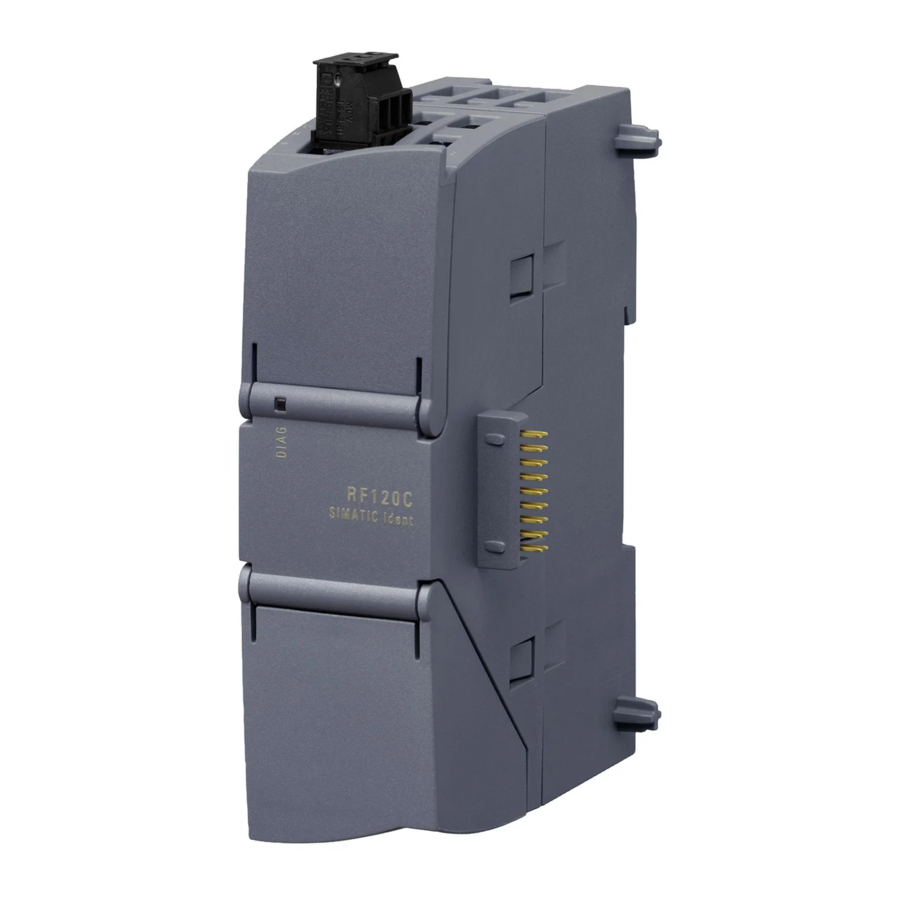
- Page 12 Table of contents RF120C ..........................391 RF160C ..........................391 RF170C ..........................392 RF180C ..........................393 RF182C ..........................394 System diagnostics ..........................395 10.1 Error codes ........................... 395 10.2 Diagnostics functions - STEP 7 Classic ................397 10.2.1 Overview ..........................397 10.2.2 Reader diagnostics with SLG STATUS ................
-
Page 13: Introduction
Introduction Navigating in the system manual Structure of the content Content Contents Detailed organization of the documentation, including the index of pages and chapters Introduction Purpose, structure and description of the important topics. Safety Information Refers to all the valid technical safety aspects which have to be adhered to while installing, commissioning and operating from the product/system view and with reference to statutory regulations. -
Page 14: Preface
RF382R Scanmode in the relevant manuals. Additional information (https://support.industry.siemens.com/cs/ww/en/ps/15033) Registered trademarks SIMATIC ®, SIMATIC RF ®, MOBY ®, RF MANAGER ® and SIMATIC Sensors ® are registered trademarks of Siemens AG. History Currently released versions of the SIMATIC RF300 system manual: Edition... - Page 15 Introduction 1.2 Preface Edition Remark 03/2014 Revised edition, expanded by the reader functionalities "RF300 transponder" and "ISO transponder" for the SIMATIC RF340R and SIMATIC RF350R readers Expanded by the following components: Reader • RF310R with Scanmode, RF382R with Scanmode Communications module •...
- Page 16 Introduction 1.2 Preface SIMATIC RF300 System Manual, 07/2016, C79000-G8976-C345-0x...
-
Page 17: Safety Information
Safety information SIMATIC RFID products comply with the salient safety specifications acc. to IEC, VDE, EN, UL and CSA. If you have questions about the permissibility of the installation in the planned environment, please contact your service representative. WARNING Opening the device Do not open the device when when the power supply is on. - Page 18 Safety information Repairs WARNING Repairs only by authorized qualified personnel Repairs may only be carried out by authorized qualified personnel. Unauthorized opening of and improper repairs to the device may result in substantial damage to equipment or risk of personal injury to the user. System expansions Only install system expansions intended for this system.
- Page 19 Siemens recommends strongly that you regularly check for product updates. For the secure operation of Siemens products and solutions, it is necessary to take suitable preventive action (e.g. cell protection concept) and integrate each component into a holistic, state-of-the-art industrial security concept.
- Page 20 Safety information SIMATIC RF300 System Manual, 07/2016, C79000-G8976-C345-0x...
-
Page 21: System Overview
System overview RFID systems RFID systems from Siemens control and optimize material flow. They identify reliably, quickly and economically, are insensitive to contamination and store data directly on the product or workpiece carrier. Table 3- 1 Overview of SIMATIC RFID systems... -
Page 22: Simatic Rf300
System overview 3.2 SIMATIC RF300 SIMATIC RF300 3.2.1 System overview of SIMATIC RF300 SIMATIC RF300 is an inductive identification system specially designed for use in industrial production for the control and optimization of material flow. Thanks to its compact dimensions, RF300 is the obvious choice where installation conditions are restricted, especially for assembly lines, handling systems and workpiece carrier systems. -
Page 23: Rfid Components And Their Function
System overview 3.2 SIMATIC RF300 ● User-friendly parameter assignment and configuration with TIA Portal technological object (as of STEP 7 Basic / Professional V14 SP 1) ● Expanded functions for trained users: – Address information for the "INIT" command no longer necessary –... - Page 24 System overview 3.2 SIMATIC RF300 RF300 system components for high-performance applications Figure 3-1 High performance system overview Table 3- 4 Reader-transponder combination options for high-performance applications Transponder RF310R RF340R RF350R RF350R RF350R RF350R RF380R with ANT 1 with ANT 3 with ANT 18 with ANT 30 RF320T...
- Page 25 System overview 3.2 SIMATIC RF300 Transponder RF310R RF340R RF350R RF350R RF350R RF350R RF380R with ANT 1 with ANT 3 with ANT 18 with ANT 30 RF370T ✓ ✓ ✓ ✓ RF380T ✓ ✓ ✓ as of reader version "AS ≥ D" ✓...
- Page 26 System overview 3.2 SIMATIC RF300 RF300 system components for medium-performance applications Figure 3-2 System overview medium-performance SIMATIC RF300 System Manual, 07/2016, C79000-G8976-C345-0x...
- Page 27 System overview 3.2 SIMATIC RF300 Table 3- 5 Reader-transponder combination options for medium-performance applications Transponder / RF310R RF340R RF350R RF350R RF350R RF350R RF350R RF380R (RS-422) with ANT with ANT with ANT with ANT with ANT MDS D100 ✓ ✓ ✓ ○...
- Page 28 System overview 3.2 SIMATIC RF300 Note Note on operation of the transponders MDS D5xx and MDS E6xx Note that the transponders MDS D5xx and MDS E6xx can only be operated in conjunction with the readers of the second generation (article number "6GT2801-xBAxx"). SIMATIC RF300 System Manual, 07/2016, C79000-G8976-C345-0x...
- Page 29 System overview 3.2 SIMATIC RF300 RF300 system components for Scanmode applications Figure 3-3 Scanmode system overview SIMATIC RF300 System Manual, 07/2016, C79000-G8976-C345-0x...
- Page 30 System overview 3.2 SIMATIC RF300 Table 3- 6 Reader-transponder combination options for Scanmode applications Transponder / RF310R RF380R RF382R MDS D100 ✓ ✓ MDS D124 ✓ ✓ ✓ MDS D126 ✓ ✓ MDS D139 ✓ ✓ MDS D160 ✓ ✓ ✓...
-
Page 31: Application Areas Of Rf300
System overview 3.2 SIMATIC RF300 3.2.3 Application areas of RF300 SIMATIC RF300 is primarily used for non-contact identification of containers, palettes and workpiece holders in a closed production circuit. The data carriers (transponders) remain in the production chain and are not supplied with the products. SIMATIC RF300, with its compact transponder and reader enclosure dimensions, is particularly suitable in confined spaces. -
Page 32: System Configuration
System overview 3.3 System configuration System configuration 3.3.1 Overview The SIMATIC RF300 system is characterized by a high level of standardization of its components. This means that the system follows the TIA principle throughout: Totally Integrated Automation. It provides maximum transparency at all levels with its reduced interface overhead. - Page 33 System overview 3.3 System configuration The entire production order that is saved on the transponder can also be read manually via the WIN-LC terminal located at each workstation. This means that virtually no additional data management is required on the control computer. The production order data can also be read for servicing purposes via the mobile SIMATIC RF350M reader.
-
Page 34: Example Of Container And Cardboard Container Handling: Use Of Iso Transponders
System overview 3.3 System configuration 3.3.3 Example of container and cardboard container handling: Use of ISO transponders Containers of varying sizes are conveyed to picking workstations in a delivery center. There, the individual goods are removed and packed in cartons according to the delivery note. These cartons are marked with low-cost transponder labels and sorted to small or large packaging workstations (according to the delivery note) by being guided or transported via the corresponding conveyor system. - Page 35 System overview 3.3 System configuration Figure 3-5 Example of container and cardboard container handling SIMATIC RF300 System Manual, 07/2016, C79000-G8976-C345-0x...
- Page 36 System overview 3.3 System configuration SIMATIC RF300 System Manual, 07/2016, C79000-G8976-C345-0x...
-
Page 37: Planning The Rf300 System
Planning the RF300 system Fundamentals of application planning 4.1.1 Selection criteria for SIMATIC RF300 components Assess your application according to the following criteria, in order to choose the right SIMATIC RF300 components: ● Transmission distance (read/write distance) ● Tracking tolerances ●... - Page 38 Planning the RF300 system 4.1 Fundamentals of application planning Operating distance between transponder and reader Limit distance (maximum clear distance between upper surface of the reader and the tran- sponder, at which the transmission can still just function under normal conditions) Length of a transmission window in the x direction while maintaining the working distance (L ≠...
- Page 39 Planning the RF300 system 4.1 Fundamentals of application planning Note Transmission window with RF380R and RF382R Note that the transmission window of the reader RF380R is not square (L ≠ L ). To obtain as large a transmission window as possible, make sure that the transponder only crosses the reader in the x direction.
-
Page 40: Width Of The Transmission Window
Planning the RF300 system 4.1 Fundamentals of application planning The transponder can be used as soon as the intersection (SP) of the transponder enters the area of the transmission window. From the diagrams above, it can also be seen that operation is possible within the area between S and S . -
Page 41: Impact Of Secondary Fields
Planning the RF300 system 4.1 Fundamentals of application planning 4.1.4 Impact of secondary fields Secondary fields in the range from 0 mm to 30% of the limit distance (S ) generally always exist. They should, however, only be used during configuration in exceptional cases, since the read/write distances are very limited. - Page 42 Planning the RF300 system 4.1 Fundamentals of application planning Secondary fields without shielding The following graphic shows typical primary and secondary fields, if no shielding measures are taken. ① Main field ② Secondary field Figure 4-4 Secondary field without shielding In this arrangement, the reader can also read tags via the secondary field.
-
Page 43: Setup Help Of The Readers Of The Second Generation
Planning the RF300 system 4.1 Fundamentals of application planning Secondary fields with shielding The following graphic shows typical primary and secondary fields, with metal shielding this time. The metal shielding prevents the reader from detecting tags via the secondary field. ①... -
Page 44: Permissible Directions Of Motion Of The Transponder
Planning the RF300 system 4.1 Fundamentals of application planning Meaning of the LED operating display in the "Setup" mode The operational statuses of the reader are displayed by two LEDs. The LEDs can adopt the colors white green, red, yellow or blue and the statuses off , on , flashing : Table 4- 1 Display elements... -
Page 45: Operation In Static And Dynamic Mode
Planning the RF300 system 4.1 Fundamentals of application planning 4.1.7 Operation in static and dynamic mode Operation in static mode If working in static mode, the transponder can be operated up to the limit distance (S ). The transponder must then be positioned exactly over the reader: Figure 4-7 Operation in static mode Operation in dynamic mode... -
Page 46: Dwell Time Of The Transponder
Planning the RF300 system 4.1 Fundamentals of application planning 4.1.8 Dwell time of the transponder The dwell time is the time in which the transponder remains within the transmission window of a reader. The reader can exchange data with the transponder during this time. The dwell time is calculated thus: Dwell time of the transponder Length of the transmission window... -
Page 47: Communication Between Communications Module, Reader And Transponder
Planning the RF300 system 4.1 Fundamentals of application planning 4.1.9 Communication between communications module, reader and transponder Aids for calculating the data transmission times User-friendly calculation tools are available for the communications modules ASM 456, RF160C, RF170C and RF180C to calculate data transfer times. The calculation tools can be found on the DVD "Ident Systems Software &... -
Page 48: Field Data For Transponders, Readers And Antennas
Planning the RF300 system 4.2 Field data for transponders, readers and antennas Aids for calculating the field data You will also find a tool for calculating field data on the DVD "Ident Systems, Software & Documentation". Using this tool, among other things you can calculate the operating distance (S ), limit distance (S ) and transmission window (L). -
Page 49: Field Data Of Rf300 Transponders
Planning the RF300 system 4.2 Field data for transponders, readers and antennas Note Possible reader-transponder combinations The tables of the following section show the possible reader-transponder combinations. 4.2.1 Field data of RF300 transponders The limit distances (S ) and operating distances (S ) along with the length of the transmission window for each reader-transponder combination are listed in the tables below. - Page 50 Planning the RF300 system 4.2 Field data for transponders, readers and antennas Table 4- 4 Field data RF350R reader / ANT 1 Length of the transmission Operating distance (S Limit distance (S window (L) RF320T 1...30 RF330T 1...25 RF340T 2...55 RF350T 2...65 RF360T...
- Page 51 "distance_limiting" input parameter (you will find more detailed information in "Function manual FB 45 (https://support.industry.siemens.com/cs/ww/en/view/21738808)"). For this, values from approx. 0.5 W to approx. 2.0 W can be set in 0.25 W increments. Depending on the setting, the change to the transmission output power increases the performance in the lower operating distance (low performance) or in the upper limit distance (high performance).
-
Page 52: Field Data Of Iso Transponders (Mds D)
Planning the RF300 system 4.2 Field data for transponders, readers and antennas 4.2.2 Field data of ISO transponders (MDS D) The limit distances (S ) and operating distances (S ) along with the length of the transmission window for each reader-transponder combination are listed in the tables below. Observe the following information for field data of ISO transponders: ●... - Page 53 Planning the RF300 system 4.2 Field data for transponders, readers and antennas Table 4- 10 Field data RF340R reader Length of the transmission Operating distance (S Limit distance (S window (L) MDS D100 5...110 MDS D124 2...60 MDS D126 2...85 MDS D139 5...80 MDS D160...
- Page 54 Planning the RF300 system 4.2 Field data for transponders, readers and antennas Length of the transmission Operating distance (S Limit distance (S window (L) MDS D424 2...60 MDS D425 2...25 MDS D426 0...85 MDS D428 2...35 MDS D460 2...35 MDS D524 2...60 MDS D525 MDS D526...
- Page 55 Planning the RF300 system 4.2 Field data for transponders, readers and antennas Table 4- 14 Field data RF350R reader / ANT 18 Diameter of the transmis- Operating distance (S Limit distance (S sion window (L MDS D117 0...4 MDS D124 2...24 MDS D127 0...4...
- Page 56 Planning the RF300 system 4.2 Field data for transponders, readers and antennas Table 4- 16 Field data RF380R reader Length of the transmission window Operating distance Limit distance (S in the x direction (L ) in the y direction (L MDS D100 5...170 MDS D124...
-
Page 57: Field Data Of Iso Transponders (Mds E)
Planning the RF300 system 4.2 Field data for transponders, readers and antennas 4.2.3 Field data of ISO transponders (MDS E) The limit distances (S ) and operating distances (S ) along with the length of the transmission window for each reader-transponder combination are listed in the tables below. Observe the following information for field data of ISO transponders: ●... - Page 58 Planning the RF300 system 4.2 Field data for transponders, readers and antennas Table 4- 20 Field data RF350R reader / ANT 1 Length of the transmission Operating distance (S Limit distance (S window (L) MDS E600 5...110 MDS E611 5...110 MDS E624 2...65 All values are in mm...
-
Page 59: Minimum Clearances
Planning the RF300 system 4.2 Field data for transponders, readers and antennas 4.2.4 Minimum clearances Minimum distance from transponder to transponder The specified distances refer to a metal-free environment. For a metallic environment, the specified minimum distances must be multiplied by a factor of 1.5. The transponders designed specifically for installation in/on metal are an exception to this. - Page 60 Planning the RF300 system 4.2 Field data for transponders, readers and antennas RF310R RF340R RF350R / RF350R / RF350R / RF350R / RF350R / RF380R RF382R ANT 1 ANT 3 ANT 12 ANT 18 ANT 30 MDS D424 ≥ 100 ≥...
- Page 61 Planning the RF300 system 4.2 Field data for transponders, readers and antennas The permissible minimum distance between two RF380Rs depends on the transmit power that is set. The specified minimum distance must be multiplied by the following factor, depending on the output: Table 4- 27 Effect on the minimum distance of the transmit power with RF380R 'distance_limiting' byte...
-
Page 62: Installation Guidelines
Planning the RF300 system 4.3 Installation guidelines Installation guidelines 4.3.1 Overview The transponder and reader complete with their antennas are inductive devices. Any type of metal in the vicinity of these devices affects their functionality. Some points need to be considered during planning and installation if the values described in the "Field data (Page 48)"... - Page 63 Planning the RF300 system 4.3 Installation guidelines Table 4- 30 Flush-mounting of transponders and readers Representation Description Problem: Flush-mounting of transponders and readers is possible in principle. However, the size of the transmis- sion window is significantly reduced. The following measures can be used to counteract the reduction of the window: Remedy:...
-
Page 64: Effects Of Metal On Different Transponders And Readers
Planning the RF300 system 4.3 Installation guidelines Mounting of several readers on metal frames or racks Any reader mounted on metal couples part of the field to the metal frame. There is normally no interaction as long as the minimum distance D and metal-free areas a, b are maintained. However, interaction may take place if an iron frame is positioned unfavorably. -
Page 65: Impact On The Transmission Window By Metal
Planning the RF300 system 4.3 Installation guidelines 4.3.4 Impact on the transmission window by metal In general, the following points should be considered when mounting RFID components: ● Direct mounting on metal is allowed only in the case of specially approved transponders. ●... - Page 66 Planning the RF300 system 4.3 Installation guidelines Transponder RF310R reader Without metal On metal Flush-mounted in metal (20 mm all- round) RF340T Without metal On metal; distance 0 mm Flush-mounted in metal; distance all round 20 mm RF350T Without metal On metal;...
- Page 67 Planning the RF300 system 4.3 Installation guidelines Transponder RF310R reader Without metal On metal Flush-mounted in metal (20 mm all- round) MDS D139 Without metal On metal; distance 30 mm Flush-mounted in metal; distance all round 100 mm MDS D160 Without metal On metal;...
- Page 68 Planning the RF300 system 4.3 Installation guidelines Transponder RF310R reader Without metal On metal Flush-mounted in metal (20 mm all- round) MDS D428 Without metal On metal; distance 0 mm MDS D460 Without metal On metal; distance 10 mm MDS D524 without metal on metal;...
-
Page 69: Rf340R
Planning the RF300 system 4.3 Installation guidelines Transponder RF310R reader without metal on metal flush-mounted in metal (20 mm all- round) MDS E624 without metal on metal; distance 15 mm flush-mounted in metal; distance all round 20 mm Mounting the transponder on or in metal is only possible with the appropriate spacer or if there is adequate clearance to the metal. - Page 70 Planning the RF300 system 4.3 Installation guidelines Transponder RF340R reader Without metal On metal Flush-mounted in metal (20 mm all- round) RF370T Without metal On metal; distance 0 mm Flush-mounted in metal; distance all round 20 mm RF380T Without metal On metal;...
- Page 71 Planning the RF300 system 4.3 Installation guidelines Transponder RF340R reader Without metal On metal Flush-mounted in metal (20 mm all- round) MDS D200 Without metal On metal; distance 20 mm Flush-mounted in metal; distance all round 20 mm MDS D261 Without metal On metal;...
- Page 72 Planning the RF300 system 4.3 Installation guidelines Transponder RF340R reader Without metal On metal Flush-mounted in metal (20 mm all- round) MDS D525 without metal on metal; distance 0 mm MDS D526 without metal on metal; distance 25 mm flush-mounted in metal; distance all round 50 mm MDS D528 without metal...
-
Page 73: Rf350R
Planning the RF300 system 4.3 Installation guidelines 4.3.4.3 RF350R Reader RF350R with ANT 1 and with RF300 transponders Table 4- 38 Reduction of field data due to metal, range as %: Transponder and RF350R with ANT 1 Transponder ANT 1 without ANT 1 on metal ANT 1 flush- metal... - Page 74 Planning the RF300 system 4.3 Installation guidelines Reader RF350R with ANT 1 and with ISO transponders (MDS D) Table 4- 39 Reduction of field data due to metal, range as %: Transponder and RF350R with ANT 1 Transponder ANT 1 without ANT 1 on metal ANT 1 mounted metal...
- Page 75 Planning the RF300 system 4.3 Installation guidelines Transponder ANT 1 without ANT 1 on metal ANT 1 mounted metal in metal (40 mm all- round) MDS D423 Without metal On metal; distance 0 mm Flush-mounted in metal; distance all round 0 mm MDS D424 Without metal On metal;...
- Page 76 Planning the RF300 system 4.3 Installation guidelines Reader RF350R with ANT 1 and with ISO transponders (MDS E) Table 4- 40 Reduction of field data due to metal, range as %: Transponder and RF350R with ANT 1 Transponder ANT 1 without ANT 1 on metal ANT 1 mounted metal...
- Page 77 Planning the RF300 system 4.3 Installation guidelines Transponder ANT 3 without ANT 3 on metal ANT 3 flush- metal mounted in metal (40 mm all- round) RF350T without metal on metal; distance 0 mm flush-mounted in metal; distance all round 20 mm RF360T without metal on metal;...
- Page 78 Planning the RF300 system 4.3 Installation guidelines Transponder ANT 3 without ANT 3 on metal ANT 3 flush- metal mounted in metal (40 mm all- round) MDS D424 without metal on metal; distance 15 mm flush-mounted in metal; distance all round 25 mm MDS D425 without metal on metal;...
- Page 79 Planning the RF300 system 4.3 Installation guidelines Reader RF350R with ANT 12 and with ISO transponders (MDS D) Table 4- 44 Reduction of field data due to metal, range as %: Transponder and RF350R with ANT 12 Transponder ANT 12 without metal ANT 12 mounted in met- (0 mm all-round) MDS D117...
- Page 80 Planning the RF300 system 4.3 Installation guidelines Reader RF350R with ANT 12 and with ISO transponders (MDS E) Table 4- 45 Reduction of field data due to metal, range as %: Transponder and RF350R with ANT 12 Transponder ANT 12 without metal ANT 12 mounted in met- (0 mm all-round) MDS E623...
- Page 81 Planning the RF300 system 4.3 Installation guidelines Reader RF350R with ANT 18 and with ISO transponders (MDS D) Table 4- 47 Reduction of field data due to metal, range as %: Transponder and RF350R with ANT 18 Transponder ANT 18 without metal ANT 18 mounted in met- (10 mm all-round) MDS D124...
- Page 82 Planning the RF300 system 4.3 Installation guidelines Transponder ANT 18 without metal ANT 18 mounted in met- (10 mm all-round) MDS D522 without metal on metal, distance 0 mm flush-mounted in metal; distance all round 0 mm MDS D524 without metal on metal 15 mm flush-mounted in metal;...
- Page 83 Planning the RF300 system 4.3 Installation guidelines Reader RF350R with ANT 30 and with RF300 transponders Table 4- 49 Reduction of field data due to metal, range as %: Transponder and RF350R with ANT 30 Transponder Mounting the antenna ANT 30 without metal ANT 30 mounted in met- (20 mm all-round) RF320T...
- Page 84 Planning the RF300 system 4.3 Installation guidelines Transponder ANT 30 without metal ANT 30 mounted in met- (20 mm all-round) MDS D126 Without metal On metal; distance 25 mm Flush-mounted in metal; distance all round 50 mm MDS D160 Without metal On metal, distance 10 mm MDS D324 Without metal...
-
Page 85: Rf380R
Planning the RF300 system 4.3 Installation guidelines Transponder ANT 30 without metal ANT 30 mounted in met- (20 mm all-round) MDS D526 without metal on metal; distance 25 mm flush-mounted in metal; distance all round 50 mm MDS D528 without metal on metal, distance 0 mm Mounting the transponder on or in metal is only possible with the appropriate spacer or if there is adequate clearance to the metal. - Page 86 Planning the RF300 system 4.3 Installation guidelines Transponder Reader RF380R (RF300 mode) Without metal On metal Flush-mounted in metal (20 mm all- round) RF330T Without metal On metal; distance 0 mm RF340T Without metal On metal; distance 0 mm Flush-mounted in metal; distance all round 20 mm RF350T Without metal...
- Page 87 Planning the RF300 system 4.3 Installation guidelines Transponder Reader RF380R (ISO mode) Without metal On metal Flush-mounted in metal (20 mm all- round) MDS D124 Without metal On metal; distance 15 mm Flush-mounted in metal; distance all round 20 mm MDS D126 Without metal On metal;...
- Page 88 Planning the RF300 system 4.3 Installation guidelines Transponder Reader RF380R (ISO mode) Without metal On metal Flush-mounted in metal (20 mm all- round) MDS D424 Without metal On metal; distance 15 mm Flush-mounted in metal; distance all round 25 mm MDS D425 Without metal On metal;...
-
Page 89: Rf382R
Planning the RF300 system 4.3 Installation guidelines 4.3.4.5 RF382R Note RF382R not suitable for metallic surroundings The RF382R was not developed for reading transponders in a metallic environment. With ISO transponders (MDS D) Table 4- 54 Reduction of field data by metal (in %): Transponder and RF382R Transponder Reader RF382R (ISO mode) Without metal... -
Page 90: Chemical Resistance Of The Transponders
Planning the RF300 system 4.4 Chemical resistance of the transponders Chemical resistance of the transponders 4.4.1 Overview of the transponders and their housing materials The following sections describe the resistance to chemicals of the various transponders. Resistance to chemicals depends on the housing materials used to manufacture the transponders. -
Page 91: Polyamide 12
Planning the RF300 system 4.4 Chemical resistance of the transponders Housing material Transponder MDS D127 PA6.6 GF30 MDS D126 MDS D422 MDS D425 MDS D426 MDS D428 MDS D522 MDS D525 MDS D526 MDS D528 Note Chemical substances not listed The following sections describe the resistance of the various transponders to specific substances. - Page 92 Planning the RF300 system 4.4 Chemical resistance of the transponders Substance Test conditions Rating Concentration [%] Temperature [°C] Calcium nitrate, w. c. s. 20 ℃ ○○○○ c. s. 60 ℃ ○○○ Chlorine 20 ℃ Chrome baths, tech. 20 ℃ Iron salts, w. c.
-
Page 93: Polyphenylene Sulfide (Pps)
Planning the RF300 system 4.4 Chemical resistance of the transponders Substance Test conditions Rating Concentration [%] Temperature [°C] Detergent high 60 ℃ ○○○○ Plasticizer 60 ℃ ○○○○ Explanation of the rating ○○○○ Resistant ○○○ Practically resistant ○○ Conditionally resistant ○ Less resistant Not resistant Water solution... -
Page 94: Polycarbonate (Pc)
Planning the RF300 system 4.4 Chemical resistance of the transponders Substance Test conditions Rating Concentration [%] Temperature [°C] Sodium hydroxide solution 90 ℃ ○○○○ Nitric acid 23 ℃ ○○○○ Hydrochloric acid 80 ℃ Sulfuric acid 23 ℃ ○○○○ 80 ℃ ○○... -
Page 95: Polyvinyl Chloride (Pvc)
Planning the RF300 system 4.4 Chemical resistance of the transponders Substance Test conditions Rating Concentration [%] Temperature [°C] Perchloroethylene Acetone Alcohols ○○ Hot water (hydrolysis resistance) Explanation of the rating ○○○○ Resistant ○○○ Practically resistant ○○ Conditionally resistant ○ Less resistant Not resistant 4.4.5 Polyvinyl chloride (PVC) -
Page 96: Epoxy Resin
Planning the RF300 system 4.4 Chemical resistance of the transponders 4.4.6 Epoxy resin Table 4- 60 Chemical Resistance - epoxy resin Substance Test conditions Rating Concentration [%] Temperature [°C] Allyl chloride 20 ℃ ○○○○ Formic acid 20 ℃ ○○○○ 100% 20 ℃... - Page 97 Planning the RF300 system 4.4 Chemical resistance of the transponders Substance Test conditions Rating Concentration [%] Temperature [°C] Chromosulfuric acid 20 ℃ Citric acid 20 ℃ ○○○○ Cyanamide 20 ℃ ○○○○ Cyanides (K–, Na– among others) 60 ℃ ○○○○ Dextrin, w. 60 ℃...
-
Page 98: Pa6.6 Gf30
Planning the RF300 system 4.4 Chemical resistance of the transponders Substance Test conditions Rating Concentration [%] Temperature [°C] Phosphoric acid 60 ℃ ○○○○ 20 ℃ ○○○○ Propanol 20 ℃ ○○○○ Nitric acid 20 ℃ Hydrochloric acid 20 ℃ Brine 60 ℃ Sulfur dioxide 100% 20 ℃... -
Page 99: Guidelines For Electromagnetic Compatibility (Emc)
Planning the RF300 system 4.5 Guidelines for electromagnetic compatibility (EMC) Substance Test conditions Rating Concentration [%] Temperature [°C] Strong mineral acids Weak organic acids ○○ Strong organic acids Oxidizing acids Weak alkaline solutions ○○ Strong alkaline solutions Trichloroethylene ○○○○ Perchloroethylene ○○○○... -
Page 100: What Does Emc Mean
Planning the RF300 system 4.5 Guidelines for electromagnetic compatibility (EMC) The description is intended for "qualified personnel": ● Project engineers and planners who plan system configurations with RFID modules and have to observe the necessary guidelines. ● Fitters and service engineers who install the connecting cables in accordance with this description or who rectify defects in this area in the event of interference. -
Page 101: Basic Rules
Planning the RF300 system 4.5 Guidelines for electromagnetic compatibility (EMC) EMC measures usually consist of a complete package of measures, all of which need to be implemented in order to ensure that the plant is immune to interference. Note The plant manufacturer is responsible for the observance of the EMC directives; the plant operator is responsible for radio interference suppression in the overall plant. -
Page 102: Propagation Of Electromagnetic Interference
Planning the RF300 system 4.5 Guidelines for electromagnetic compatibility (EMC) ● Route the signal cables as close as possible to chassis surfaces. ● Twist the feed and return conductors of separately installed cables. ● Routing HF cables: avoid parallel routing of HF cables. ●... - Page 103 Planning the RF300 system 4.5 Guidelines for electromagnetic compatibility (EMC) The EMC measures are applied to all three components, in order to prevent malfunctions due to interference. When setting up a plant, the manufacturer must take all possible measures in order to prevent the occurrence of interference sources: ●...
- Page 104 Planning the RF300 system 4.5 Guidelines for electromagnetic compatibility (EMC) What interference can affect RFID? Interference source Cause Remedy Switched-mode power supply Interference emitted from the Replace the power supply current infeed Interference injected through Cable is inadequately shield- Better cable shielding the cables connected in series The reader is not connected...
- Page 105 Planning the RF300 system 4.5 Guidelines for electromagnetic compatibility (EMC) When RFID modules are used, different components in the overall system can act as a coupling path: Table 4- 63 Causes of coupling paths Coupling path Invoked by Conductors and cables Incorrect or inappropriate installation •...
-
Page 106: Cabinet Configuration
Planning the RF300 system 4.5 Guidelines for electromagnetic compatibility (EMC) 4.5.5 Cabinet configuration The influence of the user in the configuration of an electromagnetically compatible plant encompasses cabinet configuration, cable installation, ground connections and correct shielding of cables. Note For information about electromagnetically compatible cabinet configuration, please consult the installation guidelines for SIMATIC PLCs. - Page 107 Planning the RF300 system 4.5 Guidelines for electromagnetic compatibility (EMC) As a rule: ● The effect of the interference decreases as the distance between the interference source and interference sink increases. ● The interference can be further decreased by installing grounded shielding plates. ●...
- Page 108 Planning the RF300 system 4.5 Guidelines for electromagnetic compatibility (EMC) Filtering of the supply voltage External interference from the mains can be prevented by installing line filters. Correct installation is extremely important, in addition to appropriate dimensioning. It is essential that the line filter is mounted directly at the cabinet inlet.
-
Page 109: Prevention Of Interference Sources
Planning the RF300 system 4.5 Guidelines for electromagnetic compatibility (EMC) 4.5.6 Prevention of interference sources A high level of immunity to interference can be achieved by avoiding interference sources. All switched inductances are frequent sources of interference in plants. Suppression of inductance Relays, contactors, etc. -
Page 110: Equipotential Bonding
Planning the RF300 system 4.5 Guidelines for electromagnetic compatibility (EMC) 4.5.7 Equipotential bonding Potential differences between different parts of a plant can arise due to the different design of the plant components and different voltage levels. If the plant components are connected across signal cables, transient currents flow across the signal cables. -
Page 111: Cable Shielding
Planning the RF300 system 4.5 Guidelines for electromagnetic compatibility (EMC) 4.5.8 Cable shielding Signal cables must be shielded in order to prevent coupling of interference. The best shielding is achieved by installing the cables in steel tubes. However, this is only necessary if the signal cable is routed through an environment prone to particular interference. - Page 112 Planning the RF300 system 4.5 Guidelines for electromagnetic compatibility (EMC) Figure 4-19 Connection of shielding bus The shielding bus must be connected to the PE busbar. If shielded cables have to be interrupted, the shield must be continued via the corresponding connector housing.
-
Page 113: Readers
● Function manual "Ident profile and Ident blocks (https://support.industry.siemens.com/cs/ww/en/view/106368029)", ● Product Information "FB 45 and FC 45 input parameters for RF300 and ISO transponders (https://support.industry.siemens.com/cs/ww/en/view/33315697)", ● Function manual "FB 45 (https://support.industry.siemens.com/cs/ww/en/view/21738808)" as of version "AS ≥ A3". SIMATIC RF300 System Manual, 07/2016, C79000-G8976-C345-0x... - Page 114 Readers ISO 14443 functionality With all readers of the second generation of the RF300 family, you can use ISO 14443 transponders. The RF300 readers of the second generation therefore replace the MOBY E readers SLG 72 and SLG 75. Note that the readers for RF300, ISO 15963 or ISO 14443 operation must have parameters assigned.
-
Page 115: Simatic Rf310R
Readers 5.1 SIMATIC RF310R SIMATIC RF310R 5.1.1 Features SIMATIC RF310R Characteristics ① Design RS-422 interface ② Status display Area of application Identification tasks on small assembly lines in harsh industrial environments 5.1.2 RF310R ordering data Table 5- 1 RF310R ordering data Article number RF310R with RS-422 interface (3964R) 6GT2801-1AB10... -
Page 116: Pin Assignment Rf310R With Rs-422 Interface
Readers 5.1 SIMATIC RF310R 5.1.3 Pin assignment RF310R with RS-422 interface Assignment Device end 8-pin M12 + 24 V - Transmit + Transmit + Receive - Receive Unassigned Earth (shield) 5.1.4 LED operating display The operational statuses of the reader are displayed by the LEDs. The LED can adopt the colors green, red or yellow and the statuses off , on , flashing... -
Page 117: Metal-Free Area
Readers 5.1 SIMATIC RF310R 5.1.6 Metal-free area The RF310R can be flush-mounted in metal. Please allow for a possible reduction in the field data values. Figure 5-1 Metal-free area for RF310R To avoid any impact on the field data, the distance a should be ≥ 20 mm. 5.1.7 Minimum distance between RF310R readers RF310R side by side... -
Page 118: Technical Specifications
Readers 5.1 SIMATIC RF310R RF310R face-of-face ≥ 300 mm Figure 5-3 Face-of-face distance between two RF310Rs 5.1.8 Technical specifications Table 5- 3 Technical specifications of the RF310R reader with RS-422 interface 6GT2801-1AB10 Product type designation SIMATIC RF310R Radio frequencies Operating frequency, rated value 13.56 MHz Electrical data Maximum range... - Page 119 Readers 5.1 SIMATIC RF310R 6GT2801-1AB10 Mechanical specifications Housing Material Plastic PA 12 • • Color Anthracite • • Recommended distance to metal 0 mm Supply voltage, current consumption, power loss Supply voltage 24 VDC Typical current consumption 50 mA Permitted ambient conditions Ambient temperature During operation -25 to +70 ℃...
-
Page 120: Approvals
5.1 SIMATIC RF310R 5.1.9 Approvals FCC information Siemens SIMATIC RF310R (MLFB 6GT2801-1AB10); FCC ID NXW-RF310R This device complies with part 15 of the FCC rules. Operation is subject to the following two conditions: (1) This device may not cause harmful interference, and (2) this device must accept any interference received, including interference that may cause undesired operation. -
Page 121: Dimension Drawing
Readers 5.1 SIMATIC RF310R 5.1.10 Dimension drawing Figure 5-4 Dimension drawing for RF310R Dimensions in mm SIMATIC RF300 System Manual, 07/2016, C79000-G8976-C345-0x... -
Page 122: Simatic Rf310R With Scanmode
Readers 5.2 SIMATIC RF310R with Scanmode SIMATIC RF310R with Scanmode You will find detailed information on the SIMATIC RF310R with Scanmode on the Internet (https://support.industry.siemens.com/cs/ww/en/ps/15034). 5.2.1 Features SIMATIC RF310R special version Characteristics Scanmode ① Design RS-422 interface ② Status display... -
Page 123: Pin Assignment Rf310R Special Version Scanmode Rs-422 Interface
Readers 5.2 SIMATIC RF310R with Scanmode 5.2.3 Pin assignment RF310R special version Scanmode RS-422 interface Assignment Device end 8-pin M12 + 24 V - Transmit + Transmit + Receive - Receive Unassigned Earth (shield) 5.2.4 LED operating display The operational statuses of the reader are displayed by the LEDs. The LED can adopt the colors green, red or yellow and the statuses off , on , flashing : Table 5- 5 LED operating display on the reader... -
Page 124: Metal-Free Area
Readers 5.2 SIMATIC RF310R with Scanmode 5.2.6 Metal-free area The RF310R special version can be flush-mounted in metal. Please allow for a possible reduction in the field data values. Figure 5-5 Metal-free area for RF310R special version To avoid any impact on the field data, the distance a should be ≥ 20 mm. 5.2.7 Minimum distance between several readers RF310R special version side by side... -
Page 125: Technical Specifications
Readers 5.2 SIMATIC RF310R with Scanmode RF310R special version face-to-face ≥ 300 mm Figure 5-7 Face-to-face distance between two RF310R special version 5.2.8 Technical specifications Table 5- 6 Technical specifications of the RF310R reader with Scanmode 6GT2801-1AB20-0AX1 Product type designation SIMATIC RF310R Scanmode Radio frequencies Operating frequency, rated value... - Page 126 Readers 5.2 SIMATIC RF310R with Scanmode 6GT2801-1AB20-0AX1 Supply voltage, current consumption, power loss Supply voltage 24 VDC Typical current consumption 50 mA Permitted ambient conditions Ambient temperature During operation -25 to +70 ℃ • • During transportation and storage -40 to +85 ℃ •...
-
Page 127: Approvals
5.2 SIMATIC RF310R with Scanmode 5.2.9 Approvals FCC information Siemens SIMATIC RF310R (MLFB 6GT2801-1AB20-0AX1); FCC ID NXW-RF310R This device complies with part 15 of the FCC rules. Operation is subject to the following two conditions: (1) This device may not cause harmful interference, and (2) this device must accept any interference received, including interference that may cause undesired operation. -
Page 128: Dimension Drawing
Readers 5.2 SIMATIC RF310R with Scanmode 5.2.10 Dimension drawing Figure 5-8 Dimension drawing RF310R special version Scanmode Dimensions in mm SIMATIC RF300 System Manual, 07/2016, C79000-G8976-C345-0x... -
Page 129: Simatic Rf310R - Second Generation
Readers 5.3 SIMATIC RF310R - second generation SIMATIC RF310R - second generation 5.3.1 Features SIMATIC RF310R Characteristics ① Design RS-422 interface ② LED operating display Area of application Identification tasks on small assembly lines in harsh industrial environments 5.3.2 Ordering data Table 5- 7 RF310R ordering data Article number... -
Page 130: Pin Assignment Of The Rs-422 Interface
Readers 5.3 SIMATIC RF310R - second generation 5.3.3 Pin assignment of the RS-422 interface Table 5- 8 Pin assignment Assignment Device end 8-pin M12 + 24 V - Transmit + Transmit + Receive - Receive Unassigned Earth (shield) 5.3.4 LED operating display The operational statuses of the reader are displayed by two LEDs. -
Page 131: Metal-Free Area
Readers 5.3 SIMATIC RF310R - second generation 5.3.6 Metal-free area The RF310R can be flush-mounted in metal. Allow for a possible reduction in the field data. To avoid any influence on the field data, the distance "a" should be kept to. a ≥... -
Page 132: Technical Specifications
Readers 5.3 SIMATIC RF310R - second generation RF310R face-of-face D ≥ 300 mm Figure 5-11 Face-of-face distance between two RF310Rs 5.3.8 Technical specifications Table 5- 10 Technical specifications of the RF310R reader with RS-422 interface 6GT2801-1BA10 Product type designation SIMATIC RF310R Radio frequencies Operating frequency, rated value 13.56 MHz... - Page 133 Readers 5.3 SIMATIC RF310R - second generation 6GT2801-1BA10 Mechanical specifications Housing Material Plastic PA 12 • • Color TI-Grey • • Recommended distance to metal 0 mm Supply voltage, current consumption, power loss Supply voltage 24 VDC Typical current consumption 55 mA Permitted ambient conditions Ambient temperature...
-
Page 134: Approvals
5.3 SIMATIC RF310R - second generation 5.3.9 Approvals FCC information Siemens SIMATIC RF310R (MLFB 6GT2801-1BA10); FCC ID NXW-RF310R-03 This device complies with part 15 of the FCC rules. Operation is subject to the following two conditions: (1) This device may not cause harmful interference, and (2) this device must accept any interference received, including interference that may cause undesired operation. -
Page 135: Dimension Drawing
Readers 5.3 SIMATIC RF310R - second generation UL information (IEC61010-1 / IEC61010-2-201) This standard applies to equipment designed to be safe at least under the following conditions: ● a) indoor use; ● b) altitude up to 2 000 m; ● c) temperature -25 °C to 70 °C; ●... -
Page 136: Simatic Rf340R/Rf350R
Readers 5.4 SIMATIC RF340R/RF350R SIMATIC RF340R/RF350R 5.4.1 SIMATIC RF340R 5.4.1.1 Features SIMATIC RF340R Characteristics ① Design RS-422 interface ② Status display Area of application Identification tasks on assembly lines in harsh industrial environments 5.4.1.2 Ordering data for RF340R Table 5- 11 Ordering data for RF340R Article number RF340R with RS-422 interface (3964R) -
Page 137: Pin Assignment Of Rf340R Rs422 Interface
Readers 5.4 SIMATIC RF340R/RF350R 5.4.1.3 Pin assignment of RF340R RS422 interface Assignment Device end 8-pin M12 + 24 V - Transmit + Transmit + Receive - Receive Unassigned Earth (shield) 5.4.1.4 LED operating display The operational statuses of the reader are displayed by the LEDs. The LED can adopt the colors green, red or yellow and the statuses off , on , flashing : Table 5- 12... -
Page 138: Metal-Free Area
Readers 5.4 SIMATIC RF340R/RF350R 5.4.1.6 Metal-free area The RF340R can be flush-mounted in metal. Please allow for a possible reduction in the field data values. Figure 5-13 Metal-free area for RF340R To avoid any impact on the field data, the distance a should be ≥ 20 mm. 5.4.1.7 Minimum distance between RF340R readers RF340R side by side... -
Page 139: Technical Specifications
Readers 5.4 SIMATIC RF340R/RF350R RF340R face-of-face ≥ 500 mm Figure 5-15 Face-of-face distance between two RF340Rs 5.4.1.8 Technical specifications Table 5- 13 Technical specifications of the RF340R reader 6GT2801-2AB10 Product type designation SIMATIC RF340R Radio frequencies Operating frequency, rated value 13.56 MHz Electrical data Maximum range... - Page 140 Readers 5.4 SIMATIC RF340R/RF350R 6GT2801-2AB10 Mechanical specifications Housing Material Plastic PA 12 • • Color Anthracite • • Recommended distance to metal 0 mm Supply voltage, current consumption, power loss Supply voltage 24 VDC Typical current consumption 100 mA Permitted ambient conditions Ambient temperature During operation -25 to +70 ℃...
-
Page 141: Approvals
5.4 SIMATIC RF340R/RF350R 5.4.1.9 Approvals FCC information Siemens SIMATIC RF340R (MLFB 6GT2801-2AA10); FCC ID NXW-RF340R Siemens SIMATIC RF340R (MLFB 6GT2801-2AB10); FCC ID NXW-RF340R01 This device complies with part 15 of the FCC rules. Operation is subject to the following two conditions:... -
Page 142: Dimension Drawing
Readers 5.4 SIMATIC RF340R/RF350R 5.4.1.10 Dimension drawing Figure 5-16 Dimension drawing for RF340R Dimensions in mm SIMATIC RF300 System Manual, 07/2016, C79000-G8976-C345-0x... -
Page 143: Simatic Rf350R
Readers 5.4 SIMATIC RF340R/RF350R 5.4.2 SIMATIC RF350R 5.4.2.1 Features SIMATIC RF350R Characteristics ① Design Antenna connection ② RS-422 interface ③ Status display Area of application Identification tasks in assembly lines in harsh industrial environments; for external antennas (ANT 1, ANT 3, ANT 12, ANT 18, ANT 30) Note Reader requires external antennas Note that the RF350R reader is designed only for operation with external antennas and only... -
Page 144: Pin Assignment Of Rf350R Rs422 Interface
Readers 5.4 SIMATIC RF340R/RF350R 5.4.2.3 Pin assignment of RF350R RS422 interface Assignment Device end 8-pin M12 + 24 V - Transmit + Transmit + Receive - Receive Unassigned Earth (shield) 5.4.2.4 LED operating display The operational statuses of the reader are displayed by the LEDs. The LED can adopt the colors green, red or yellow and the statuses off , on , flashing : Table 5- 15... -
Page 145: Technical Specifications
Readers 5.4 SIMATIC RF340R/RF350R 5.4.2.7 Technical specifications Table 5- 16 Technical specifications of the RF350R reader 6GT2801-4AB10 Product type designation SIMATIC RF350R Radio frequencies Operating frequency, rated value 13.56 MHz Electrical data Maximum range ANT 1 140 mm • • ANT 3 50 mm •... - Page 146 Readers 5.4 SIMATIC RF340R/RF350R 6GT2801-4AB10 Supply voltage, current consumption, power loss Supply voltage 24 VDC Typical current consumption 100 mA Permitted ambient conditions Ambient temperature During operation -25 to +70 ℃ • • During transportation and storage -40 to +85 ℃ •...
-
Page 147: Approvals
5.4 SIMATIC RF340R/RF350R 5.4.2.8 Approvals FCC information Siemens SIMATIC RF350R (MLFB 6GT2801-4AA10); FCC ID NXW-RF350R Siemens SIMATIC RF350R (MLFB 6GT2801-4AB10); FCC ID NXW-RF350R01 This device complies with part 15 of the FCC rules. Operation is subject to the following two conditions:... -
Page 148: Dimension Drawing
Readers 5.4 SIMATIC RF340R/RF350R 5.4.2.9 Dimension drawing Figure 5-17 RF350R dimension drawing Dimensions in mm SIMATIC RF300 System Manual, 07/2016, C79000-G8976-C345-0x... -
Page 149: Use Of The Reader In Hazardous Areas
Readers 5.4 SIMATIC RF340R/RF350R 5.4.3 Use of the reader in hazardous areas TÜV NORD CERT GmbH as accredited test center and certification body, no. 0044 as per Article 9 of the Directive 94/9/EC of the European Council of 23 March 1994, has confirmed the compliance with the essential health and safety requirements relating to the design and construction of equipment and protective systems intended for use in hazardous areas as per Annex II of the Directive. -
Page 150: Use Of The Readers In Hazardous Areas For Gases
Readers 5.4 SIMATIC RF340R/RF350R 5.4.3.1 Use of the readers in hazardous areas for gases Temperature class delineation for gases The temperature class of the reader for hazardous areas depends on the ambient temperature range: Ambient temperature range Temperature class -25 °C to +70 °C WARNING Ignitions of gas-air mixtures When using the RF340R/RF350R readers, check to ensure that the temperature class is... -
Page 151: Installation And Operating Conditions For The Hazardous Area
Readers 5.4 SIMATIC RF340R/RF350R 5.4.3.3 Installation and operating conditions for the hazardous area NOTICE Device may be damaged Note the following conditions when installing and operating the device in a hazardous zone to avoid damage: • Making and breaking of circuits is permitted only in a de-energized state. •... -
Page 152: Simatic Rf340R/Rf350R - Second Generation
Readers 5.5 SIMATIC RF340R/RF350R - second generation SIMATIC RF340R/RF350R - second generation 5.5.1 SIMATIC RF340R - second generation 5.5.1.1 Features SIMATIC RF340R Characteristics ① Design RS-422 interface ② LED operating display Area of application Identification tasks on assembly lines in harsh industrial environments 5.5.1.2 Ordering data... -
Page 153: Pin Assignment Of The Rs-422 Interface
Readers 5.5 SIMATIC RF340R/RF350R - second generation 5.5.1.3 Pin assignment of the RS-422 interface Table 5- 18 Pin assignment Assignment Device end 8-pin M12 + 24 V - Transmit + Transmit + Receive - Receive Unassigned Earth (shield) 5.5.1.4 LED operating display The operational statuses of the reader are displayed by two LEDs. -
Page 154: Metal-Free Area
Readers 5.5 SIMATIC RF340R/RF350R - second generation 5.5.1.6 Metal-free area The RF340R can be flush-mounted in metal. Allow for a possible reduction in the field data. To avoid any influence on the field data, the distance "a" should be kept to. a ≥... -
Page 155: Technical Specifications
Readers 5.5 SIMATIC RF340R/RF350R - second generation RF340R face-of-face D ≥ 500 mm Figure 5-20 Face-of-face distance between two RF340Rs 5.5.1.8 Technical specifications Table 5- 20 Technical specifications of the RF340R reader 6GT2801-2BA10 Product type designation SIMATIC RF340R Radio frequencies Operating frequency, rated value 13.56 MHz Electrical data... - Page 156 Readers 5.5 SIMATIC RF340R/RF350R - second generation 6GT2801-2BA10 Mechanical specifications Housing Material Plastic PA 12 • • Color TI-Grey • • Recommended distance to metal 0 mm Supply voltage, current consumption, power loss Supply voltage 24 VDC Typical current consumption 55 mA Permitted ambient conditions Ambient temperature...
-
Page 157: Approvals
5.5 SIMATIC RF340R/RF350R - second generation 5.5.1.9 Approvals FCC information Siemens SIMATIC RF340R (MLFB 6GT2801-2BA10); FCC ID NXW-RF340R-03 This device complies with part 15 of the FCC rules. Operation is subject to the following two conditions: (1) This device may not cause harmful interference, and (2) this device must accept any interference received, including interference that may cause undesired operation. -
Page 158: Dimension Drawing
Readers 5.5 SIMATIC RF340R/RF350R - second generation UL information (IEC61010-1 / IEC61010-2-201) This standard applies to equipment designed to be safe at least under the following conditions: ● a) indoor use; ● b) altitude up to 2 000 m; ● c) temperature -25 °C to 70 °C; ●... -
Page 159: Simatic Rf350R - Second Generation
Readers 5.5 SIMATIC RF340R/RF350R - second generation 5.5.2 SIMATIC RF350R - second generation 5.5.2.1 Features SIMATIC RF350R Characteristics ① Design Antenna connection ② RS-422 interface ③ LED operating display Area of application Identification tasks in assembly lines in harsh industrial environments; for external antennas (ANT 1, ANT 3, ANT 12, ANT 18, ANT 30) Note Reader requires external antennas... -
Page 160: Pin Assignment Of The Rs-422 Interface
Readers 5.5 SIMATIC RF340R/RF350R - second generation 5.5.2.3 Pin assignment of the RS-422 interface Table 5- 22 Pin assignment Assignment Device end 8-pin M12 + 24 V - Transmit + Transmit + Receive - Receive Unassigned Earth (shield) 5.5.2.4 LED operating display The operational statuses of the reader are displayed by two LEDs. -
Page 161: Metal-Free Area
Readers 5.5 SIMATIC RF340R/RF350R - second generation 5.5.2.6 Metal-free area The RF350R reader does not have an internal antenna. Operation is not affected by mounting on metal or flush-mounting in metal. For information about the metal-free area required by the external antennas, refer to the corresponding section of the chapter "Antennas (Page 193)". - Page 162 Readers 5.5 SIMATIC RF340R/RF350R - second generation 6GT2801-4BA10 Mechanical specifications Housing Material Plastic PA 12 • • Color TI-Grey • • Recommended distance to metal 0 mm Supply voltage, current consumption, power loss Supply voltage 24 VDC Typical current consumption 55 mA Permitted ambient conditions Ambient temperature...
-
Page 163: Approvals
5.5 SIMATIC RF340R/RF350R - second generation 5.5.2.8 Approvals FCC information Siemens SIMATIC RF350R (MLFB 6GT2801-4BA10); FCC ID NXW-RF350R-03 This device complies with part 15 of the FCC rules. Operation is subject to the following two conditions: (1) This device may not cause harmful interference, and (2) this device must accept any interference received, including interference that may cause undesired operation. -
Page 164: Dimension Drawing
Readers 5.5 SIMATIC RF340R/RF350R - second generation UL information (IEC61010-1 / IEC61010-2-201) This standard applies to equipment designed to be safe at least under the following conditions: ● a) indoor use; ● b) altitude up to 2 000 m; ● c) temperature -25 °C to 70 °C; ●... -
Page 165: Use Of The Reader In Hazardous Areas
Readers 5.5 SIMATIC RF340R/RF350R - second generation 5.5.3 Use of the reader in hazardous areas NOTICE Approvals for the hazardous area The approvals for the hazardous area of the readers SIMATIC RF340R und RF350R are currently in preparation. SIMATIC RF300 System Manual, 07/2016, C79000-G8976-C345-0x... -
Page 166: Simatic Rf380R
Readers 5.6 SIMATIC RF380R SIMATIC RF380R 5.6.1 Features SIMATIC RF380R Characteristics ① Design RS-232 or RS-422 interface ② Status display Area of application Identification tasks on assembly lines in harsh industrial environments 5.6.2 RF380R ordering data Table 5- 25 RF380R ordering data Article number RF380R with RS-232/RS-422 interface (3964R) 6GT2801-3AB10... - Page 167 Readers 5.6 SIMATIC RF380R Note correct assignment of the pins here: Assignment Device end RS-232 RS-422 8-pin M12 + 24 V + 24 V - Transmit + Transmit not used + Receive not used - Receive not used not used Ground (shield) Ground (shield) 5.6.4...
- Page 168 Readers 5.6 SIMATIC RF380R 5.6.6 Metal-free area The RF380R can be flush-mounted in metal. Please allow for a possible reduction in the field data values. Figure 5-23 Metal-free area for RF380R To avoid any impact on the field data, the distance a should be ≥ 20 mm. 5.6.7 Minimum distance between RF380R readers RF380R side by side...
- Page 169 Readers 5.6 SIMATIC RF380R RF380R face-to-face ≥ 800 mm Figure 5-25 Face-to-face distance between two RF380R 5.6.8 Technical specifications Table 5- 27 Technical specifications of the RF380R reader 6GT2801-3AB10 Product type designation SIMATIC RF380R Radio frequencies Operating frequency, rated value 13.56 MHz Electrical data Maximum range...
- Page 170 Readers 5.6 SIMATIC RF380R 6GT2801-3AB10 Mechanical specifications Housing Material Plastic PA 12 • • Color Anthracite • • Recommended distance to metal 0 mm Supply voltage, current consumption, power loss Supply voltage 24 VDC Typical current consumption 160 mA Permitted ambient conditions Ambient temperature During operation -25 to +70 ℃...
- Page 171 5.6 SIMATIC RF380R 5.6.9 Approvals FCC information Siemens SIMATIC RF380R (MLFB 6GT2801-3AA10); FCC ID NXW-RF380R Siemens SIMATIC RF380R (MLFB 6GT2801-3AB10); FCC ID NXW-RF380R01 This device complies with part 15 of the FCC rules. Operation is subject to the following two conditions:...
- Page 172 Readers 5.6 SIMATIC RF380R 5.6.10 Use of the reader in hazardous areas The TÜV SÜD Automotive GmbH as approved test center as well as the TÜV SÜD Product Service GmbH as certification center, identification number 0123, as per Article 9 of the Directive of the European Council of 23 March 1994 (94/9/EC), has confirmed the compliance with the essential health and safety requirements relating to the design and construction of equipment and protective systems intended for use in hazardous areas as...
- Page 173 Readers 5.6 SIMATIC RF380R 5.6.11 Use of the reader in hazardous areas for gases Temperature class delineation for gases The temperature class of the reader for hazardous areas depends on the ambient temperature range: Ambient temperature range Temperature class -25 °C to +70 °C WARNING Ignitions of gas-air mixtures When using the RF380R reader, check to ensure that the temperature class is observed in...
- Page 174 Readers 5.6 SIMATIC RF380R 5.6.13 Dimension drawing Figure 5-26 Dimension drawing RF380R Dimensions in mm SIMATIC RF300 System Manual, 07/2016, C79000-G8976-C345-0x...
- Page 175 Readers 5.7 SIMATIC RF380R with Scanmode SIMATIC RF380R with Scanmode You will find detailed information on the SIMATIC RF382R with Scanmode on the Industry Online Support - SIMATIC RF380R with Scanmode (https://support.industry.siemens.com/cs/ww/en/ps/15037). 5.7.1 Features RF380R Scanmode Characteristics ① Design RS232 or RS422 interface ②...
- Page 176 You can connect the RF380R Scanmode reader via the internal RS-232/RS-422 interface to a higher-level system. (See section "Basic rules (Page 101)") Make sure that the pin assignment is correct. In the factory settings, the reader is set to RS-232. Siemens can change the interface to RS-422.
- Page 177 Readers 5.7 SIMATIC RF380R with Scanmode 5.7.6 Metal-free area The RF380R can be flush-mounted in metal. Please allow for a possible reduction in the field data values. Figure 5-27 Metal-free area for RF380R To avoid any impact on the field data, the distance a should be ≥ 20 mm. 5.7.7 Minimum distance between several RF380R Scanmode readers RF380R side by side...
- Page 178 Readers 5.7 SIMATIC RF380R with Scanmode RF380R face-to-face ≥ 800 mm Figure 5-29 Face-to-face distance between two RF380R 5.7.8 Technical specifications Table 5- 31 Technical specifications of the RF380R Scanmode reader 6GT2801-3AB20-0AX1 Product type designation SIMATIC RF380R Scanmode Radio frequencies Operating frequency, rated value 13.56 MHz Electrical data...
- Page 179 Readers 5.7 SIMATIC RF380R with Scanmode 6GT2801-3AB20-0AX1 Supply voltage, current consumption, power loss Supply voltage 24 VDC Typical current consumption 160 mA Permitted environmental conditions Ambient temperature -25 to +70 °C During operation • -40 to +85 °C Transport and storage •...
- Page 180 5.7 SIMATIC RF380R with Scanmode 5.7.9 Approvals FCC information Siemens SIMATIC RF380R (MLFB 6GT2801-3AB20-0AX1); FCC ID NXW-RF380R01 This device complies with part 15 of the FCC rules. Operation is subject to the following two conditions: (1) This device may not cause harmful interference, and (2) this device must accept any interference received, including interference that may cause undesired operation.
- Page 181 Readers 5.7 SIMATIC RF380R with Scanmode 5.7.10 Certificates and Approvals Certificates for USA and Canada Underwriters Laboratories (UL) acc. to standard UL 60950, Report E11 5352 and Ca- nadian standard C22.2 No. 60950 (I.T.E) or acc. to UL508 and C22.2 No. 142 (IND.CONT.EQ) 5.7.11 Dimension drawing...
- Page 182 Readers 5.8 SIMATIC RF382R with Scanmode SIMATIC RF382R with Scanmode You will find detailed information on the SIMATIC RF382R with Scanmode on the Internet (https://support.industry.siemens.com/cs/ww/en/ps/15038). 5.8.1 Characteristics RF382R Scanmode Characteristics ① Design RS-232 or RS-422 interface ② Status display Operating range Suitable for high speeds, e.g.
- Page 183 You can connect the RF382R Scanmode reader via the internal RS-232/RS-422 interface or via a higher-level system. (See section "Basic rules (Page 101)") Make sure that the pin assignment is correct. In the factory settings, the reader is set to RS-232. Siemens can change the interface to RS-422.
- Page 184 Readers 5.8 SIMATIC RF382R with Scanmode 5.8.7 Minimum distance between several RF382R Scanmode readers Figure 5-31 Minimum distance between several RF382R Scanmode readers Minimum distance D from RF382R to RF382R D ≥ 200 mm 5.8.8 Transmission window Orientation of fields of the SIMATIC RF382R Scanmode For many applications it may be best to operate the reader so that the tags move from left to right (or from right to left) at a certain distance in front of the narrow edge of the reader.
- Page 185 Readers 5.8 SIMATIC RF382R with Scanmode Maximum field strength The reader creates the maximum field approximately 13 mm below the upper reader edge. For the largest possible reading range the tags you want to read should move in this range. This applies regardless of whether the horizontal or the vertical field is used.
- Page 186 Readers 5.8 SIMATIC RF382R with Scanmode Transmission window horizontal field Figure 5-35 Distance definition horizontal field Green Main field (processing field) Blue Secondary fields, horizontal field Maximum length of the main field, horizontal field Distance from the reader edge at which maximum horizontal main field length L exists Operating range in the main field Limit distance ①...
- Page 187 Readers 5.8 SIMATIC RF382R with Scanmode Limit distance (S ③ The limit distance lies on Level Transmission window vertical field Figure 5-36 Distance definition vertical field Green Main field (processing field) Maximum length of the main field, vertical field Distance from the reader edge at which maximum vertical main field length L exists Operating range in the main field Limit distance...
- Page 188 Readers 5.8 SIMATIC RF382R with Scanmode 5.8.9 Technical specifications Table 5- 35 Technical specifications of the RF382R reader with Scanmode 6GT2801-3AB20-0AX0 Product type designation SIMATIC RF382R Scanmode Radio frequencies Operating frequency, rated value 13.56 MHz Electrical data Maximum range 75 mm Maximum data transmission speed ISO transponder reader ↔...
- Page 189 EN 301489, CE, FCC, UL/CSA 5.8.10 Approvals FCC information Siemens SIMATIC RF382R (MLFB 6GT2801-3AB20-0AX0); FCC ID NXW-RF382R This device complies with part 15 of the FCC rules. Operation is subject to the following two conditions: (1) This device may not cause harmful interference, and (2) this device must accept any interference received, including interference that may cause undesired operation.
- Page 190 Readers 5.8 SIMATIC RF382R with Scanmode Note This equipment has been tested and found to comply with the limits for a Class A digital device, pursuant to part 15 of the FCC Rules. These limits are designed to provide reasonable protection against harmful interference when the equipment is operated in a commercial environment.
- Page 191 Readers 5.8 SIMATIC RF382R with Scanmode 5.8.11 Dimensional diagram Figure 5-37 Dimension drawing SIMATIC RF300 System Manual, 07/2016, C79000-G8976-C345-0x...
- Page 192 Readers 5.8 SIMATIC RF382R with Scanmode SIMATIC RF300 System Manual, 07/2016, C79000-G8976-C345-0x...