Siemens SIMATIC Ident Operating Instructions Manual
Hide thumbs
Also See for SIMATIC Ident:
- System manual (362 pages) ,
- Function manual (142 pages) ,
- Operating manual (80 pages)
Table of Contents
Advertisement
Quick Links
SIMATIC Ident
RFID systems
SIMATIC RF120C
Operating Instructions
02/2021
C79000-G8976-C328-03
Introduction
Description
Mounting, connecting up
and commissioning
Configuration and
parameter assignment
Service and maintenance
Technical data
Dimension drawings
Appendix
Service & Support
1
2
3
4
5
6
7
A
B
Advertisement
Table of Contents

Related Manuals for Siemens SIMATIC Ident


Summary of Contents for Siemens SIMATIC Ident
- Page 1 Introduction Description Mounting, connecting up SIMATIC Ident and commissioning Configuration and parameter assignment RFID systems SIMATIC RF120C Service and maintenance Technical data Operating Instructions Dimension drawings Appendix Service & Support 02/2021 C79000-G8976-C328-03...
- Page 2 Note the following: WARNING Siemens products may only be used for the applications described in the catalog and in the relevant technical documentation. If products and components from other manufacturers are used, these must be recommended or approved by Siemens. Proper transport, storage, installation, assembly, commissioning, operation and maintenance are required to ensure that the products operate safely and without any problems.
-
Page 3: Table Of Contents
Table of contents Introduction ............................5 Security information ......................6 Description ............................. 7 Area of application and features ................... 7 Setup and configuration ...................... 8 Integration ........................10 Mounting, connecting up and commissioning ..................11 Important notes on using the device .................. 11 Installing and commissioning the RF120C ................ - Page 4 Table of contents Connecting cable ....................... 44 A.2.1 Routing of standard cables ....................44 A.2.2 Self-assembled cables ......................47 Connection of serial devices via Freeport protocol .............. 48 A.3.1 Compatible Ident devices ....................48 A.3.2 Connecting handheld readers / access control readers / serial devices ......... 48 A.3.3 Hardware configuration .....................
-
Page 5: Introduction
1200 programmable controller (https://support.industry.siemens.com/cs/ww/en/view/109772940)". • The manuals of the relevant IID system (https://support.industry.siemens.com/cs/ww/en/ps/14970/man) contain information on the readers and optical code readers to be connected. • You can find information on configuration and parameter assignment, as well as on the reset blocks, in the "Ident profile and Ident blocks, standard function for Ident systems... -
Page 6: Security Information
Do not dispose of the products at public disposal sites. For environmentally compliant recycling and disposal of your electronic waste, please contact a company certified for the disposal of electronic waste or your Siemens representative. Note the different country-specific regulations. -
Page 7: Description
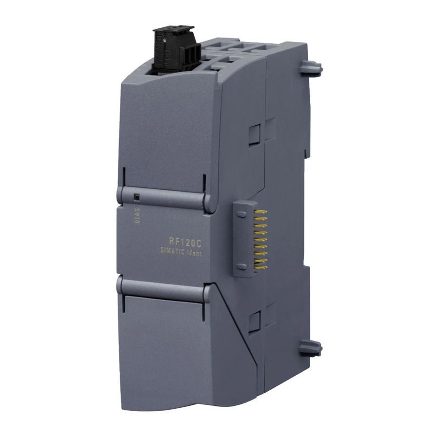
Description Area of application and features Area of application The SIMATIC RF120C communications module is a module for the SIMATIC S7-1200 controllers. The RF120C can be used as a central I/O device in a SIMATIC S7-1200 with firmware version ≥ 3.0. Figure 2-1 RF120C communications module When operating the communications modules with a SIMATIC S7-1200, there is a global... -
Page 8: Setup And Configuration
Description 2.2 Setup and configuration Only one reader or one optical reader can be operated with a SIMATIC RF120C communication module via an RS232/RS422 interface. RFID readers and optical readers from the following product families can be operated with the RF120C: •... - Page 9 Description 2.2 Setup and configuration ① RF120C communications module ② CPU SIMATIC S7-1200 ③ Signal modules ④ DIN rail mounting clip ⑤ DIN rail / panel Figure 2-2 SIMATIC S7-1200 with RF120C Configuration The following figure shows the SIMATIC S7-1200 with three RF120C communications modules.
-
Page 10: Integration
Description 2.3 Integration Integration Integration The figure below shows how the SIMATIC S7-1200 with RF120C is integrated into an automation system. Figure 2-4 Example of integrating a SIMATIC S7-1200 with RF120C As of STEP 7 Basic/Professional V13, the communication module RF120C (V1.0) is integrated in the TIA Portal;... -
Page 11: Mounting, Connecting Up And Commissioning
Mounting, connecting up and commissioning Important notes on using the device Safety notices on the use of the device The following safety notices must be adhered to when setting up and operating the device and during all work relating to it such as installation, connecting up, replacing devices or opening the device. -
Page 12: Installing And Commissioning The Rf120C
Mounting, connecting up and commissioning 3.2 Installing and commissioning the RF120C Overvoltage protection NOTICE Protection of the external 24 VDC voltage supply If the module is supplied via widespread 24 V power supply cables or networks, coupling of strong electromagnetic pulses into the power supply cables is possible, for example due to lightning or the switching of large loads. - Page 13 Mounting, connecting up and commissioning 3.2 Installing and commissioning the RF120C Dimensions for installation Figure 3-1 Dimensions for installation of the S7-1200 Table 3- 1 Dimensions for installation S7-1200 devices Width A Width B * CPU ② Width depends on the CPU being used 90 mm 45 mm 110 mm...
- Page 14 Mounting, connecting up and commissioning 3.2 Installing and commissioning the RF120C Procedure for installation and commissioning Note Installation location All RF120C communications modules must be installed to the left beside the SIMATIC S7- 1200. During installation, make sure that the upper and lower ventilation slits of the module are not obstructed and good ventilation is possible.
- Page 15 Mounting, connecting up and commissioning 3.2 Installing and commissioning the RF120C Table 3- 2 Installing and connecting up an RF120C Task Procedure 1. Remove the bus cover on the left of the CPU: Insert a screwdriver into the slot above the bus cover. –...
- Page 16 Mounting, connecting up and commissioning 3.2 Installing and commissioning the RF120C Table 3- 3 Dismantling an RF120C Task Procedure 1. Make sure that the CPU and all S7-1200 devices are disconnected from the electric power. 2. Remove the two plug-in connectors from the CPU and the RF120C. 3.
-
Page 17: Connecting Readers / Serial Devices
Mounting, connecting up and commissioning 3.3 Connecting readers / serial devices Connecting readers / serial devices NOTICE Correct usage When connecting non-specified devices to the RF120C, it is possible that the connected device may be destroyed. A pre-assembled cable therefore permits the optimum and simple connection of the reader. The standard version of the connecting cable is available in lengths 2 m, 5 m and 10 m. - Page 18 Mounting, connecting up and commissioning 3.3 Connecting readers / serial devices At the top right behind the upper door in the housing of the module the version is printed as a placeholder "X". You require the version if you have questions for Support. In the example "X 2 3 4", the "X"...
-
Page 19: External Power Supply
Mounting, connecting up and commissioning 3.4 External power supply External power supply Power supply The 3-pin socket for the external 24 VDC power supply is located on the top of the module. The reader is supplied with voltage via this power supply. The matching plug with screw terminals ships with the product. -
Page 20: Pin Assignment Of The Socket For The External Power Supply
Mounting, connecting up and commissioning 3.5 Pin assignment of the socket for the external power supply Pin assignment of the socket for the external power supply Figure 3-5 Socket for the external 24 VDC power supply (view from above) Table 3- 4 Pin assignment of the socket for the external power supply Labeling Function... -
Page 21: Configuration And Parameter Assignment
A more in-depth parameter assignment of the communication module RF120C (V2.0) as well as the devices connected to it, takes place via the technology object "SIMATIC Ident > TO_Ident" of the TIA Portal as of V17. SIMATIC RF120C... -
Page 22: Module Parameters" Parameter Group
RF120C using special Reset blocks. You can find detailed information on the Reset blocks in the function manual "Ident profile and Ident blocks, standard function for Ident systems (https://support.industry.siemens.com/cs/ww/en/ps/14970/man)". The "Parameter" main menu item is divided into the following parameter groups: • Module parameters •... -
Page 23: Frame" Parameter Group
Configuration and parameter assignment 4.3 Parameter assignment with the device configuration Parameter Parameter value Default value Description Diagnostics None Hard errors With this parameter, you set whether hardware messages diagnostic messages will be reported. Hard errors • None: Apart from standard diagnostics, no other alarms are generated. - Page 24 Configuration and parameter assignment 4.3 Parameter assignment with the device configuration Parameter Parameter value Default value Description Specifying end detec- After character delay After character delay Specifies the end detection of a received frame: tion time elapses time elapses • After character delay time elapses: On receipt of fixed num- ber of characters...
-
Page 25: Programming Via Simatic Controller
STEP 7 as of version V13. You can find a detailed description of the Ident profile and the Ident blocks in the "Ident profile and Ident blocks, standard function for Ident systems (https://support.industry.siemens.com/cs/ww/en/view/109781633)" function manual. SIMATIC RF120C Operating Instructions, 02/2021, C79000-G8976-C328-03... -
Page 27: Service And Maintenance
Service and maintenance LED status display on the RF120C Position of the display elements and the electrical connectors The LEDs for detailed display of the module statuses are located behind the upper door in the housing. Open the upper door in the housing by pulling it down. To allow this, the doors in the housing are extended to form a handle. - Page 28 Service and maintenance 5.1 LED status display on the RF120C Table 5- 1 LEDs below the upper cover of the housing LED / colors Name Meaning DC 24 V Indicates that voltage is being applied via the external 24 V power supply.
-
Page 29: Diagnostics
Service and maintenance 5.2 Diagnostics Diagnostics NOTICE The diagnostics options are limited Error messages that the RF120C communications module forwards automatically to the SIMATIC controller are not evaluated by S7-1200 controllers with firmware version 4.0. For this reason error messages from the communications module are displayed neither on the controller nor in the TIA Portal. - Page 30 Service and maintenance 5.2 Diagnostics Procedure Proceed as follows to read the diagnostic status of the RF120C using STEP 7 Basic / Professional (TIA Portal): 1. Change to the Project view. 2. Right-click on the desired communications module and click on "Online & Diagnostics" in the shortcut menu.
-
Page 31: Error Messages
You can find a detailed description of all error messages and their possible causes and remedies in the "Ident profile and Ident blocks, standard function for Ident systems (https://support.industry.siemens.com/cs/ww/en/view/109781633)" Function Manual. Error messages displayed via the "ERR" LED The following error messages from the communications module are indicated by the flashing... -
Page 33: Technical Data
Technical data Table 6- 1 Technical specifications of the RF120C 6GT2002-0LA00 Product type designation SIMATIC RF120C Transmission speed Maximum transmission speed on point-to-point connections (serial) 115.2 Kbps Interfaces Design of the interface for RS422, RS232 point-to-point connection Max. cable length •... - Page 34 Technical data 6GT2002-0LA00 Mechanical specifications Material Xantar MX 1094 Color Ti-Grey 24L01 Dimensions (W x H x D) 30 x 100 x 75 mm Weight 0.15 kg Type of mounting S7-1200 module rack Maximum tightening torque of 0.45 Nm the screw for securing the equipment Environmental conditions Ambient temperature •...
-
Page 35: Dimension Drawings
Dimension drawings Figure 7-1 Dimension drawing RF120C communications module (dimensions in mm) SIMATIC RF120C Operating Instructions, 02/2021, C79000-G8976-C328-03... -
Page 37: Appendix
SIMATIC NET/SIMATIC Ident products are regularly submitted to the authorities and approval centers for approvals relating to certain markets and applications. Contact your Siemens representative if you need a list of the current approvals for the individual devices or check the Internet pages of Siemens Industry Online Support: Current approvals (https://support.industry.siemens.com/cs/ww/en/ps/15666) - Page 38 Siemens Aktiengesellschaft Process Industries and Drives Process Automation D-76181 Karlsruhe Germany You will find the CE Declaration of Conformity for this product on the Internet at the following address: CE declaration of conformity (https://support.industry.siemens.com/cs/ww/en/ps/15109/cert) SIMATIC RF120C Operating Instructions, 02/2021, C79000-G8976-C328-03...
- Page 39 WARNING Risk of explosion in hazardous areas When using SIMATIC NET/SIMATIC Ident products in Zone 2 hazardous areas, it is essential that you pay attention to the associated special conditions in the document: "SIMATIC NET Product Information Use of subassemblies/modules in a Zone 2 Hazardous Area".
- Page 40 Appendix A.1 Certificates & approvals The SIMATIC Ident products described in these operating instructions meet the requirements of the EU directive 2014/34/EU "Equipment and protective systems for use in hazardous areas". Note Type of protection of the device The devices are approved for various types of protection. You can find the type of protection of your device and the ATEX certificate number on the nameplate.
- Page 41 Appendix A.1 Certificates & approvals IECEx The SIMATIC Ident products described in these operating instructions meet the requirements of explosion protection acc. to IECEx. Note Type of protection of the device The devices are approved for various types of protection. You can find the type of protection of your device and the IECEx certificate number on the nameplate.
-
Page 42: Standards And Test Regulations
Appendix A.1 Certificates & approvals The product meets the requirements of the standards: • Factory Mutual Approval Standard Class Number 3611 • FM Hazardous (Classified) Location Electrical Equipment: Non Incendive / Class I / Division 2 / Groups A,B,C,D / T4 and Non Incendive / Class I / Zone 2 / Group IIC / T4 A.1.2 Standards and test regulations... - Page 43 Appendix A.1 Certificates & approvals Environmental conditions Environmental conditions - transportation and storage EN 60068-2-2, Test Bb, dry heat and -40 ℃ ... +70 ℃ EN 60068-2-1 Test Ab, cold EN 60068-2-30, Test Db, damp heat 25 ℃ to 55 ℃, 95% humidity EN 60068-2-14, Test Na, temperature shock -40 ℃...
-
Page 44: Connecting Cable
Appendix A.2 Connecting cable Connecting cable A.2.1 Routing of standard cables You can connect the various readers and optical readers using the following connecting cables. • Connecting cable D-sub (RS422) ↔ M12 for RF200, RF300, MV400 and MV500 Length: 2 m, 5 m, 10 m An additional CM adapter cable (6GF3500-8BA11 or 6GF3500-8BA12) is required to connect the MV500. - Page 45 Appendix A.2 Connecting cable • Connecting cable D-sub (RS232) ↔ RJ50 for MV320 Length: 1.6 m coiled; can be extended to 4.0 m D-sub connector (male) RJ50 connector (female) • Extension cable M12 ↔ M12 for RF200, RF300 and MV400 Length: 2 m, 5 m, 10 m, 20 m, 50 m M12 connector (male) M12 connector (female)
- Page 46 Appendix A.2 Connecting cable • Connecting cable M12 ↔ D-sub for MOBY D Can only be used in conjunction with a connecting cable D-sub-D (RS422) ↔M12 (6GT2091-4Lxxx). Length: 2 m M12 connector (male) D-sub connector (female) 1, 8 Note: Reader with a D-sub connector must be supplied over an additional connector with 24 V DC. •...
-
Page 47: Self-Assembled Cables
A reader connector with screw terminals is available for self-assembly (see the relevant system manual). Cables and reader connectors can be ordered using the TIA Selection Tool, the SIMATIC Ident Configuration Guide. Maximum cable length The readers (RS232) connected to the communication module can be operated with a maximum cable length of 15 m. -
Page 48: Connection Of Serial Devices Via Freeport Protocol
The manuals of the relevant devices contain information on the parameterization options for the devices stated in the following: • SIMATIC MV320 (https://support.industry.siemens.com/cs/ww/en/ps/15157/man) • SIMATIC RF1000 (https://support.industry.siemens.com/cs/ww/en/ps/24223/man) You will find the parameter assignment options of other serial devices in the manuals of the respective device vendor. -
Page 49: Hardware Configuration
Appendix A.3 Connection of serial devices via Freeport protocol Power supply The connected field device can be supplied with power via the communication module if the performance data of the communication module is not exceeded. Note the technical specifications of the RF120C in this respect: At 24 V max. 0.8 A or at 5 V max. 0.6 A. A.3.3 Hardware configuration The optical handheld readers and access control readers can be integrated into SIMATIC... - Page 50 Appendix A.3 Connection of serial devices via Freeport protocol Configuring the optical handheld readers To allow the operation of the optical handheld readers via the RS232 interface with the communication module you need to configure the handheld readers appropriately. This configuration can be achieved quickly and simply by scanning the relevant codes.
-
Page 51: Functions And Commands
Reset_Reader As an alternative to the "Reset_Univ" command, this command can be used with using the technology object "SIMATIC Ident > TO_Ident". You can find detailed information on the commands and error messages of the RF1040R/RF1070R in the "Programming" section of the "SIMATIC RF1000" manual. The system job frames displayed must be stored in the data area for the "Write"... - Page 52 Appendix A.3 Connection of serial devices via Freeport protocol Notes on the commands and functions Reset_* Communication with the CM is initialized with the Reset command. The Reset command does not have reader-specific parameters and triggers the deletion of the buffers. The communication module is ready for operation after the "Reset_*".
-
Page 53: Block-Specific Error Messages
Appendix A.3 Connection of serial devices via Freeport protocol A.3.5 Block-specific error messages The following table lists the block-specific error codes that can occur when working with optical handheld readers, access control readers or serial devices. Table A- 4 Block-specific error messages Error ID Meaning 0xE1FE0300... -
Page 54: Ordering Data
Appendix A.4 Ordering data Ordering data A.4.1 Ordering data for RF120C Table A- 5 Ordering data Article number RF120C communications module 6GT2002-0LA00 Table A- 6 Ordering data - Accessories Article number Connecting cable D-sub (RS422) ↔ M12; 6GT2091-4LH20 for RF200/RF300, MV400/MV500 6GT2091-4LH50 10 m 6GT2091-4LN10... -
Page 55: Ordering Data For Simatic S7-1200 Accessories
Appendix A.4 Ordering data A.4.2 Ordering data for SIMATIC S7-1200 accessories You will find the complete ordering overview for the SIMATIC S7-1200 • in the Operating Instructions "S7-1200 Programmable Controller" or • in the catalog "ST 70, Totally Integrated Automation and Micro Automation". A.4.3 Further ordering data Table A- 7... -
Page 57: Service & Support
Industry Online Support In addition to the product documentation, you are supported by the comprehensive online information platform of Siemens Industry Online Support at the following Internet address: Link: (https://support.industry.siemens.com/cs/de/en/) Apart from news, you will also find the following there: •... - Page 58 Service & Support SIMATIC RF120C Operating Instructions, 02/2021, C79000-G8976-C328-03...