Table of Contents
Advertisement
Quick Links
USER GUIDE
NI CB-2162
Single-Ended Digital I/O Accessory
Contents
The NI CB-2162 is a connector block and prototyping board for
National Instruments digital waveform generator/analyzer modules.
The NI CB-2162 provides an easy way to complete the following tasks:
•
Terminate digital I/O (DIO) and control channels
•
Connect to other devices for testing and debugging
•
Develop and interface to prototype circuits
•
Probe DIO and control channels
This guide explains how to set up and use the NI CB-2162 single-ended
DIO accessory.
What You Need to Get Started ............................................................... 2
Related Documentation........................................................................... 3
Parts Locator Diagram ............................................................................ 4
Installing Cables...................................................................................... 5
Connecting Signals ................................................................................. 6
Terminating Signals ................................................................................ 12
Using the NI CB-2162 Prototyping Area................................................ 15
Mounting the NI CB-2162 in an Enclosure ............................................ 17
Specifications .......................................................................................... 21
Where to Go for Support......................................................................... 22
Advertisement
Table of Contents

Related Manuals for NI CB-2162


Summary of Contents for NI CB-2162
-
Page 1: Table Of Contents
• Develop and interface to prototype circuits • Probe DIO and control channels This guide explains how to set up and use the NI CB-2162 single-ended DIO accessory. Contents What You Need to Get Started ............... 2 Related Documentation................3 Parts Locator Diagram ................ -
Page 2: What You Need To Get Started
❑ Resistors and 10-pin single-inline packaged resistor networks for pull-up/pull-down and series termination ❑ The NI CB-2162 ships populated with a 0 Ω resistor. A 50 Ω resistor also is included for optional STROBE/PFI 5 series termination. ❑ 30-gauge wire ❑... -
Page 3: Related Documentation
The titles and location of the documents vary based on the instrument driver that supports the NI device, but you should have the following types of documentation: •... -
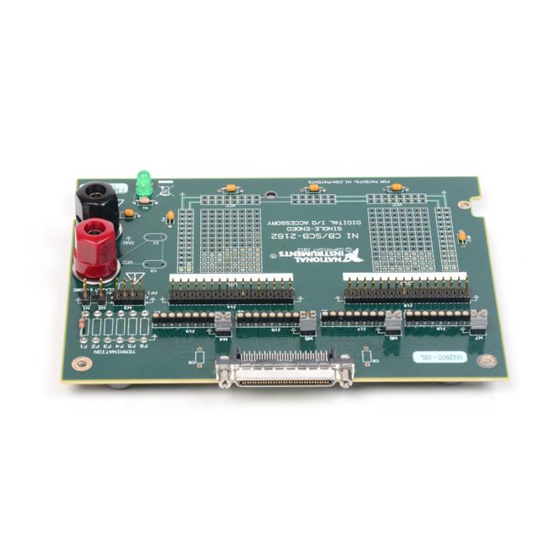
Page 4: Parts Locator Diagram
Parts Locator Diagram Refer to Figure 1 to locate connectors and components on the NI CB-2162. F6 F5 F4 F3 F2 F1 4/DDC CLKOUT STROBE 1 68-Pin Digital Data & Control (DDC) Connector 6 Prototyping Area Power and Ground Solder Pads... -
Page 5: Installing Cables
Before connecting the cable, disconnect power from the module, accessory, and Caution any other connected hardware to prevent damage to the hardware and personal injury. NI is not liable for damage resulting from improper connections. Install NI-HSDIO or NI-DAQmx and the digital waveform generator/analyzer by following the installation procedure in the Getting Started Guide that shipped with your device. -
Page 6: Connecting Signals
Refer to Figure 1 for the location of these pins on the NI CB-2162. Before powering down the digital waveform generator/analyzer module, remove Caution power from the prototyping area of the NI CB-2162. NI is not liable for any damage resulting from improper signal connections. NI CB-2162 User Guide... - Page 7 Figure 3 shows the DDC connector pinout of the NI CB-2162. DIO 31 DIO 30 DIO 29 DIO 28 DIO 27 DIO 26 DIO 25 DIO 24 RESERVED DIO 23 DIO 22 DIO 21 DIO 20 DIO 19 DIO18 DIO 17...
- Page 8 Examples of how to make these connections are provided in the following sections. Connections that exceed any of the maximum ratings for the NI CB-2162 or the Caution NI digital waveform generator/analyzer module can damage the module and the computer.
- Page 9 Using 1 × 2 Header Receptacles Each signal and ground header pair is labeled on the NI CB-2162 and in Figure 1. These header pairs are arranged so that you can make quick connections using a 1 × 2 header receptacle to a coaxial cable assembly.
- Page 10 Using a Ribbon Cable The header pairs on the NI CB-2162 are available for single wire probing. You also can use 32-pin ribbon cables to easily connect a large number of channels to other devices. Cable type and quality can dramatically affect how well the signal integrity is maintained.
- Page 11 Connect the DIO channel and ground header pins for each channel being used. Figure 6 provides an illustration for making a wire-wrap connection. 1 Wire-Wrap Tool 3 Header Pin Receptacle 2 Stripped Wire Figure 6. Wire-Wrap Connections © National Instruments Corporation NI CB-2162 User Guide...
-
Page 12: Terminating Signals
To minimize the effect of stubs, termination is placed at the end of the signal path. If your signal transmission line ends on the NI CB-2162, you can use the provided termination socket. If your signal terminates somewhere other than the NI CB-2162, NI recommends terminating the transmission line at the final signal destination. - Page 13 Thevenin (Dual) Termination In some applications, you might need to provide a Thevenin (dual) termination or a pull-up and pull-down configuration. Figure 9 shows a typical dual-termination resistor network, which can accomplish this task. © National Instruments Corporation NI CB-2162 User Guide...
- Page 14 DDC CLK OUT/PFI_4 (W2) J5, J6 (F2) Parallel (pull-down) RESERVED/PFI_0 (F3) Parallel (pull-down) PFI 1 (W3) J7, J8 (F4) Parallel (pull-down) PFI 2 (W3) J9, J10 (F5) Parallel (pull-down) PFI 3 (W3) J11, J12 (F6) Parallel (pull-down) NI CB-2162 User Guide ni.com...
-
Page 15: Using The Ni Cb-2162 Prototyping Area
Using the NI CB-2162 Prototyping Area The NI CB-2162 prototyping area is designed to aid you in the following tasks: •... - Page 16 Replacing Components The NI CB-2162 does not use replaceable fuses. If you need to replace the LED, choose a replacement that meets the specifications described in the Specifications section.
-
Page 17: Mounting The Ni Cb-2162 In An Enclosure
You will not need the washers to mount the NI CB-2162 in the CA-1000. Save the Note washers in case you ever need to remove the NI CB-2162 from the CA-1000 and use the NI CB-2162 outside the enclosure. © National Instruments Corporation... - Page 18 Figure 12. Position the NI CB-2162 on the standoffs of the CA-1000. Secure the NI CB-2162 in the bottom of the CA 1000 using two of the screws provided in the NI CB-2162 CA-1000 Mounting Kit. Place the lower edge of the VHDCI panellete in the groove at the bottom of the enclosure opening.
- Page 19 10. Reattach the DDC connector jackscrews through the opening in the I/O panelette. 1 DDC Screws 3 CA 1000 5 NI CB-2162 2 VHDCI Panelette 4 Standoffs Figure 12. Secure the NI CB-2162 and Attach the I/O Panelette © National Instruments Corporation NI CB-2162 User Guide...
- Page 20 12. Install I/O panelettes in the unused panelette openings, as shown in Figure 13. The panelettes in the following figure are blank, but you can purchase many other types of I/O panelettes from NI. For more information on the other I/O panelettes, go to and search for ni.com...
-
Page 21: Specifications
Dimensions..........10 × 14 cm (3.94 × 5.51 in.) I/O connectors ........68-pin DDC connector, two banana-style connectors, 76 header pins, 4 termination sockets (8 DIO per socket) Weight ............ 82 g (2.9 oz) © National Instruments Corporation NI CB-2162 User Guide... -
Page 22: Where To Go For Support
NI Application Engineers. National Instruments corporate headquarters is located at 11500 North Mopac Expressway, Austin, Texas, 78759-3504. National Instruments also has offices located around the world to help address your support needs. - Page 23 National Instruments, NI, ni.com, and LabVIEW are trademarks of National Instruments Corporation. Refer to the Terms of Use section on ni.com/legal for more information about National Instruments trademarks. Other product and company names mentioned herein are trademarks or trade names of their respective companies. For patents covering National Instruments products, refer to the appropriate location: Help»Patents in your software, the patents.txt file on your CD, or...
Need help?
Do you have a question about the CB-2162 and is the answer not in the manual?
Questions and answers