Advertisement
Quick Links
Advertisement

Summary of Contents for NI PXI-2571
- Page 1 PXI-2571 Features 2024-03-27...
- Page 2 PXI-2571 Overview........
- Page 3 PXI-2571 Features PXI-2571 Overview PXI-2571 Pinout © National Instruments...
- Page 4 PXI-2571 Features COM0 NC50 COM1 COM50 COM2 NO50 COM3 NC51 COM4 COM51 COM5 NO51 COM6 NC52 COM7 COM52 COM8 NO52 COM9 NC53 NC10 COM10 COM53 NO10 NC11 COM11 NO53 NO11 NC12 COM12 NC54 NO12 NC13 COM13 COM54 NO13 NC14 COM14...
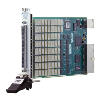
- Page 5 Signal Description COMx Routing destination for corresponding signal connections Normally closed signal connection Normally open signal connection — No connection PXI-2571 Hardware Diagram This figure shows the hardware diagram of the module. COM0 COM1 COM2 COM3 NC65 COM65 NO65 PXI-2571 Topology Module software name: 2571/66-SPDT (NISWITCH_TOPOLOGY_2571_66_SPDT) The module is composed of 66 armature-latching SPDT relays.
- Page 6 PXI-2571 Features Note Switching inductive loads (for example, motors and solenoids) can produce high voltage transients in excess of the module's rated voltage. Without additional protection, these transients can interfere with module operation and impact relay life. 66-SPDT Topology (NC0)
- Page 7 Refer to the following table for information about ordering replacement relays. Replacement Relay Part Number AXICOM (Tyco Electronics) (relay manufacturer) IM42PNS (7-1462039-8) NI relay kit (10 relays) 781678-01 Ensure you have the following: Temperature-regulated soldering iron set to 371 °C (700 °F) for lead-free ■...
- Page 8 PXI-2571 Features Note NI recommends using lead-free solder for relay replacement on lead-free assemblies, and lead solder for relay replacement on lead assemblies. Notice Do not rework lead assemblies using a lead-free work station. Lead solder from the unit could contaminate the station.
- Page 9 — 3. Replace the relay as you would any other through-hole part. Use the NI-SWITCH Switch Soft Front Panel to reset the relay count after you have replaced a failed relay. Refer to the Switch Soft Front Panel Help for more information.


Need help?
Do you have a question about the PXI-2571 and is the answer not in the manual?
Questions and answers