
Related Manuals for NI PXIe-4322


Summary of Contents for NI PXIe-4322
- Page 1 NI SC Express NI PXIe-4322 User Manual NI PXIe-4322 User Manual April 2013 373754A-01...
- Page 2 Worldwide Technical Support and Product Information ni.com Worldwide Offices Visit ni.com/niglobal to access the branch office Web sites, which provide up-to-date contact information, support phone numbers, email addresses, and current events. National Instruments Corporate Headquarters 11500 North Mopac Expressway Austin, Texas 78759-3504 USA Tel: 512 683 0100...
- Page 3 Important Information Warranty The NI PXIe-4322 is warranted against defects in materials and workmanship for a period of one year from the date of shipment, as evidenced by receipts or other documentation. National Instruments will, at its option, repair or replace equipment that proves to be defective during the warranty period.
- Page 4 For patents covering National Instruments products/technology, refer to the appropriate location: Help»Patents in your software, the file on your media, or the National Instruments Patent Notice at patents.txt ni.com/patents Export Compliance Information Refer to the Export Compliance Information at for the National Instruments global ni.com/legal/export-compliance...
-
Page 5: Table Of Contents
TB-4322 Accessory ..................2-14 Accessory Auto-Detection................2-14 Isolation ......................2-14 Chapter 3 NI SC Express Considerations PXI and NI SC Express Clock and Trigger Signals ............3-1 PXIe_CLK100 ......................3-1 PXIe_SYNC100 ....................... 3-1 PXI_CLK10......................3-1 PXI Triggers ......................3-1 PXI_STAR Trigger....................3-2... - Page 6 Cascaded Voltage Output Channels Diagram ........2-3 Figure 2-5. Cascade Current Output Channels Diagram.......... 2-4 Figure 2-6. NI PXIe-4322 Block Diagram ............... 2-7 Figure 2-7. Analog Output Timing Options............. 2-9 Figure 2-8. AO Sample Clock and AO Start Trigger..........2-10 Figure 2-9.
- Page 7 Compliance Electromagnetic Compatibility Guidelines This product was tested and complies with the regulatory requirements and limits for electromagnetic compatibility (EMC) stated in the product specifications. These requirements and limits provide reasonable protection against harmful interference when the product is operated in the intended operational electromagnetic environment.
-
Page 8: Getting Started
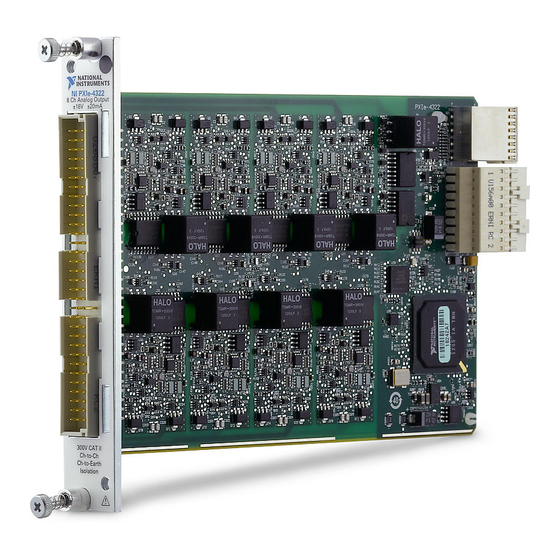
(DAC) and can be configured as voltage output mode or current output mode. The voltage mode has ±16 V output range and the current mode has ±20 mA output range. Installation Refer to the NI PXIe-4322 and TB-4322 Installation Guide and Terminal Block Specifications for step-by-step software and hardware installation instructions. Module Specifications Refer to the NI PXIe-4322 Specifications document for module specifications. -
Page 9: Using The Ni Pxie-4322
Block Specifications document for details about signal terminal locations. You can connect a load to each channel of the NI PXIe-4322. Connect the positive lead of the load to the AO+ terminal. Connect the ground of the load to the corresponding AO- terminal as shown in Figure 2-1. -
Page 10: Increasing Output Voltage Range In Voltage Output Mode
Increasing Output Voltage Range in Voltage Output Mode Each channel of the NI PXIe-4322 has a nominal output voltage range of ±16 V and can drive up to ±20 mA of current. If you want to increase the nominal output voltage range, you can cascade up to eight output channels, as shown in Figure 2-4, for a maximum of ±128 V nominal. -
Page 11: Increasing Output Current Range In Current Output Mode
Increasing Output Current Range in Current Output Mode Each channel of the NI PXIe-4322 has a nominal output current range of ±20 mA within its nominal compliance voltage of ±16 V. If you want to increase the nominal output current range, you can connect up to eight current mode output channels in parallel, as shown in Figure 2-5, for a maximum of ±160 mA nominal. -
Page 12: Device Pinout
PXIe-4322 TB-4322 Device Pinout This is the pinout represented on the front connector of the NI PXIe-4322. Refer to the Connector Signal Description section for definitions of each signal. Refer to the terminal block installation guide for signal locations on the terminal block. -
Page 13: Table 2-1. Front Signal Pin Assignments
NI PXIe-4322 User Manual Table 2-1. Front Signal Pin Assignments Front Connector Diagram Pin Number Column A Column B Column C Channel — AO 0+ AOS 0+ — AO 0- AOS 0- Column — — — — AO 1+ AOS 1+ —... -
Page 14: I/O Connector Signal Description
Chapter 2 Using the NI PXIe-4322 I/O Connector Signal Description Table 2-2 describes the signals found on the I/O connectors. Table 2-2. I/O Connector Signal Descriptions NI-DAQmx Signal Names Signal Name Description AO <0..7>+, AO <0..7> Analog Output Channels 0 to 7. AO+ is the positive AO <0..7>-... -
Page 15: Ni Pxie-4322 Block Diagram
Software-Timed Generations With a software-timed generation, software controls the rate at which data is generated. Software sends a separate command to the hardware to initiate each DAC conversion. In NI-DAQmx, software-timed generations are referred to as on-demand timing. Software-timed generations are also referred to as immediate or static operations. -
Page 16: Hardware-Timed Generations
HWTSP ideal for real-time control applications. HWTSP operations, in conjunction with the wait for next sample clock function, provide tight synchronization between the software layer and the hardware layer. Refer to the NI Developer Zone document, NI-DAQmx Hardware-Timed Single Point Lateness Checking, for more information. To access this... -
Page 17: Analog Output Timing Signals
Timebase Clock Divider 20 MHz Timebase 100 kHz Timebase PXI_CLK10 The NI PXIe-4322 features the following analog output (waveform generation) timing signals: • AO Sample Clock Signal (digital filtering supported) • AO Sample Clock Timebase Signal (digital filtering not supported) AO Sample Clock Signal Use the AO Sample Clock (ao/SampleClock) signal to initiate AO samples. -
Page 18: Using An External Source
A programmable internal counter divides down the AO Sample Clock Timebase signal. Several other internal signals can be routed to AO Sample Clock through internal routes. Refer to Device Routing in MAX in the NI-DAQmx Help or the LabVIEW Help for more information. Using an External Source Use one of the following external signals as the source of AO Sample Clock: •... -
Page 19: Getting Started With Ao Applications In Software
External Reference Clock An external reference clock can be used as a source for the internal timebase on the NI PXIe-4322. This clock can be sourced using the signals shown in Table 2-3. Since the clock © National Instruments | 2-11... -
Page 20: 10 Mhz Reference Clock
10 MHz Reference Clock The 10 MHz reference clock can be used to synchronize other devices to the NI PXIe-4322 module. The 10 MHz reference clock can be routed to the PXI_Trig <0..7> terminals. Other devices connected to the PXI_Trig bus can use this signal as a clock input. -
Page 21: Synchronizing Multiple Devices
Digital Input Triggering You can configure the NI PXIe-4322 device to start or pause an acquisition in response to a digital trigger signal from either PXIe_DSTAR <A, B>, PXI_Trig<0..7>, or PXI_STAR. The trigger circuit can respond to a rising, falling, or level sensitive signal, in one of the following three modes: •... -
Page 22: Tb-4322 Accessory
Instruments»NI-DAQ»NI-DAQmx Help. Accessory Power The NI PXIe-4322 provides auxiliary power for accessories connected to the module and has protection in the event of a fault condition. If a fault occurs in the form of an over-power condition, the power supply latches off until it is reset. To reset after a fault condition perform a Device Reset in MAX or programmatically in your ADE. - Page 23 This category refers to local-level electrical distribution, such as that provided by a standard wall outlet, for example, 115 V for U.S. or 230 V for Europe. Do not connect the NI PXIe-4322 module to signals or use for measurements within Measurement Categories III or IV.
-
Page 24: Ni Sc Express Considerations
NI SC Express Considerations PXI clock and trigger signals are only available on PXI Express devices. PXI and NI SC Express Clock and Trigger Signals PXIe_CLK100 PXIe_CLK100 is a common low-skew 100 MHz reference clock for synchronization of multiple modules in a PXI Express measurement or control system. The PXIe backplane is responsible for generating PXIe_CLK100 independently to each peripheral slot in a PXI Express chassis. -
Page 25: Pxi_Star Trigger
Chapter 3 NI SC Express Considerations On SC Express modules, the eight PXI trigger signals are synonymous with PXI_Trig <0..7>. Note that in a PXI chassis with more than eight slots, the PXI trigger lines may be divided into multiple independent buses. Refer to the documentation for your chassis for details. -
Page 26: Data Transfer Methods
CPU. This method makes DMA the fastest available data transfer method. NI uses DMA hardware and software technology to achieve high throughput rates and increase system utilization. DMA is the default method of data transfer for PCI Express and PXI Express devices. -
Page 27: Technical Support And Professional Services
Engineers make sure every question submitted online receives an answer. – Standard Service Program Membership—This program entitles members to direct access to NI Applications Engineers via phone and email for one-to-one technical support, as well as exclusive access to self-paced online training modules at ni.com/ . - Page 28 Appendix A Technical Support and Professional Services You also can visit the Worldwide Offices section of to access the branch ni.com/niglobal office Web sites, which provide up-to-date contact information, support phone numbers, email addresses, and current events. A-2 | ni.com...
Need help?
Do you have a question about the PXIe-4322 and is the answer not in the manual?
Questions and answers