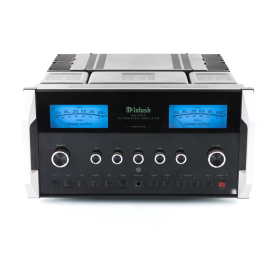
McIntosh MA7000 Service Manual
Integrated amplifier
Hide thumbs
Also See for MA7000:
- Owner's manual (20 pages) ,
- Connection diagrams (2 pages) ,
- Programming manual (21 pages)
Advertisement
Quick Links
Performance Specifications ..........................................2
Notes ...........................................................................2
Rear Panel ...................................................................3
Section Location ..........................................................4
Block Diagram .......................................................5 - 6
Interconnection Diagram ........................................7 - 8
Backup Power Supply Schematic and PCB............9 - 10
Main Schematic and PCB ...................................11 - 22
Display Schematic and PCB................................23 - 26
SERVICE MANUAL
MA7000
INTEGRATED
AMPLIFIER
SERIAL NO. YK1001 And Above
CONTENTS
Pushbutton Schematic and PCB ..........................27 - 30
Balanced Schematic and PCB .............................31 - 34
Preamp Schematic and PCB ...............................35 - 38
Capacitor Schematic and PCB ............................39 - 42
Heatsink Schematic and PCB ..............................43 - 46
Meter Light Schematic and PCB ..........................47 - 48
Parts List .............................................................49 - 56
Repacking Instruction ................................................57
MA7000
Advertisement

Related Manuals for McIntosh MA7000


Summary of Contents for McIntosh MA7000
-
Page 1: Table Of Contents
MA7000 MA7000 INTEGRATED AMPLIFIER SERIAL NO. YK1001 And Above CONTENTS Performance Specifications ..........2 Pushbutton Schematic and PCB ......27 - 30 Notes ................2 Balanced Schematic and PCB ......31 - 34 Rear Panel ..............3 Preamp Schematic and PCB .......35 - 38 Section Location ............4 Capacitor Schematic and PCB ......39 - 42... -
Page 2: Performance Specifications
240 Volts, 50/60Hz at 3.3 amps Phono, 1.2 mV Standby: Less than 1 watt Power Amp In, 2.5V Note: Refer to the rear panel of the MA7000 for the Signal To Noise Ratio (A-Weighted) correct voltage. High Level, 100dB below rated output... -
Page 3: Rear Panel
MA7000 REAR PANEL... -
Page 4: Section Location
SECTION LOCATIONS... -
Page 5: Block Diagram
MA7000 BLOCK DIAGRAM... - Page 6 INTERCONNECT...
- Page 7 MA7000 BACKUP POWER SUPPLY 751060 SCH and PCB AC FUSE J17:1 +VBU AC N J17:2 PRIMARY 1000uF J16:4 +VBU +VBU J16:5 J16:1 POWER 1 0 0 V 1 2 0 V 2 2 0 V 2 4 0 V 100V...
- Page 8 MAIN 750856 SCH 1 of 5 IN OUT +15V 1.1A 1.1A 1.1A POWER RLY IN OUT -15V J8:1 +VBU RELAY +VBU J8:4 IN OUT J8:5 AC DETECT 22.1k...
- Page 9 MA7000 MAIN 750856 SCH 2 of 5 INPUT RELAY DECODER +15V THERM FRONT REAR REC OUT SERVER LED SERVER RLY DATA DATA CD2 LED CD2 RLY SCLK SCLK REC LED REC RLY RESET REC OUT RLY TUNER LED TUNER RLY...
- Page 10 MAIN 750856 SCH 3 of 5 L PRE J16:2 R PRE J16:1 R62B R62A R64B R64A R66B R66A DVD RLY CD1 RLY PHONO RLY 22uF +15V 100uF +15V U13B 47uF R INP 22.1 U16B -15V J16:5 10uF LEFT OUTPUT 2 UNBAL TO BAL AM P -15V J16:6...
- Page 11 MA7000 MAIN 750856 SCH 4 of 5 L B+ L B+ L B+ +15V +14L R105 -15V -14L R122 R106 R128 L DRV FB J24:5 VOLTAGE .0068uF 47 .5W +65V DIFFERENTIAL L B+ J24G 47 .5W 10uF R112 R113 -65V...
- Page 12 MAIN 750856 SCH 5 of 5 R151 R B+ R B+ R B+ +15V +14R R152 -15V -14R C110 C111 C112 C113 C105 R DRV FB J26:5 VOLTAGE .0068uF R140 +65V J26:7 47 .5 W R B+ DIFFERENTIAL C109 R157 R158 10uF -65V...
- Page 13 MA7000 MAIN 750856 PCB 129903...
- Page 14 R MET FB J6:6 ILLUM PWR ON MONO LED J3:23 100k J6:8 OUT1 LED OUT1 CTRL L PG J3:20 MA7000 PreAmp OUT2 LED OUT2 CTRL R METER ADJ ACC CTRL MUTE 2.21k L METER J3:21 HDPH RLY T/O DELAY L MET [+]...
- Page 15 MA7000 DISPLAY/HEADPHONE 750680 PCB HEADPHONE...
- Page 16 PUSHBUTTON 750681 SCH McIntosh MA7000 P1324 Pushbutton PCB Assy PC BD 129834 COL0/RES TUN/STBY J1:2 J1:3 Insertion Assy PCB Assy 750681 COL0 REC/MUTE J1:4 J1:5 COL1 SRVR/OUT2 J1:6 J1:7 ROW 0 STANDBY/ON MUTE OUTPUT 2 COL2 DVD/OUT1 J1:14 J1:9 ROW 2...
- Page 17 MA7000 PUSHBUTTON 750681 PCB...
- Page 18 BALANCED 750682 SCH 100pF 10uF +15V 10uF -15V RIGHT BAL TO UNBAL AMP BAL R J1:12 +15V -15V BAL L J1:2 100pF J1:10 10uF J1:3 +15V J1:8 +15V +15V J1:1 -15V J1:6 -15V 10uF J1:11 J1:4 -15V LEFT BAL TO UNBAL AMP .1uF .1uF CD1 / DVD...
- Page 19 MA7000 BALANCED 750682 PCB...
- Page 20 100k 100k 100k R22A R27A R32A R37A R42A 470pF 10uF .047uF 1.5uF .01uF .47uF .0033uF .15uF .001uF McIn tosh .033uF -15V2 -15V2 -15V2 -15V2 +15V2 -15V2 MA7000 P1324 Preamp PCB Assy PC BD 129836 Insertion Assy 702455 PCB Assy 750683...
- Page 21 MA7000 PREAMP 750683 PCB...
- Page 22 CAPACITOR 750685 SCH BR [+] J5:1 + 65V BR [-] - 65V J5:2 Y EL J6:1 + 65V J6:2 - 65V...
- Page 23 MA7000 CAPACITOR 750685 PCB...
- Page 24 HEATSINK 750684 SCH DRIVER Q10A Q12A OUTPUTS CURRENT Q14A LIMITER + 65V J1:1 +65V Q16A - 65V J1:2 -65V Q18A 1.1k J3:1 BIAS [+] 1.1k J3:2 BIAS [-] Q10B Q12B Q16B Q18B .47x2 .47x2 .47x2 OUTPUT .47x2 .47x2 .47x2 Q11B Q13B Q17B Q19B...
- Page 25 MA7000 HEATSINK 750684 PCB...
- Page 26 METER LIGHT 750845 SCH and PCB +5.6V J1:12 +5.6V J1:11 +5.6V J1:10 J1:9 J1:8 J1:7 McIntosh J1:6 MA7000 P1324 Meter Light PCB Assy J1:5 PC BD Insertion Assy J1:4 PCB Assy 310373 +5.6V J1:3 +5.6V J1:2 +5.6V J1:1 129899...
-
Page 27: Parts List
MA7000 PARTS LIST INTERCONNECT Ref. No. Description Part No. Ref. No. Description Part No. THERMISTOR 5 OHM 144151 ASSEMBLY CAPACITOR 052005 THERMISTOR 5 OHM 144151 CABLE ASSY MAIN/HEATSINK 171896 TRANSFORMER 8V/16V 2.5VA 159366 CABLE ASSY CAP/HEATSINK 171897 CABLE ASSY CAP/HEATSINK... - Page 28 PARTS LIST (Cont’d.) MAIN PCB 750856 (Cont’d.) Ref. No. Description Part No. Ref. No. Description Part No. C115 CAP MONO 220PF 200V 10% NPO 061342 CAP ELECT 10UF 16V 066580 C116 CAP MONO 100PF 100V 10% NPO 061341 CAP ELECT 10UF 50V 066445 C117 CAP MONO 100PF 100V 10% NPO...
- Page 29 MA7000 PARTS LIST (Cont’d.) MAIN PCB 750856 (Cont’d.) Ref. No. Description Part No. Ref. No. Description Part No. RECEPTACLE XLR MALE 117686 TRANSISTOR NPN SILICON 132317 RECEPTACLE XLR MALE 117686 TRANSISTOR NPN SILICON 132317 JACK RCA 3X2 WHT/RED 14MM 117790...
- Page 30 PARTS LIST (Cont’d.) MAIN PCB 750856 (Cont’d.) Ref. No. Description Part No. Ref. No. Description Part No. RES MF 100K 1% 1/4W 144528 RES MF 12.1K 1% 1/4W 144550 RES MET OX 47 OHM .5W 5% 137102 R100 RES MF 221 OHM 1% 1/4W 144559 R101 RES MF 10K 1% 1/4W...
- Page 31 MA7000 PARTS LIST (Cont’d.) MAIN PCB 750856 (Cont’d.) Ref. No. Description Part No. Ref. No. Description Part No. LED GREEN 5MM 30 DEG 058190 R159 RES MF 267K 1% 1/4W 144532 (DS3) SPACER LED 112108 R160 RES MF 47.5K 1% 1/4W...
- Page 32 134506 RES MF 1K 1% 1/4W 144513 IC NAND 2 INPUT X 4 133575 RES MF 20K 1% 1/4W 144524 IC PROGRAMMED V1.00 MA7000 133671 RES MF 20K 1% 1/4W 144524 (U2) SOCKET IC 40-PIN 178133 RES MF 1K 1% 1/4W...
- Page 33 MA7000 PARTS LIST (Cont’d.) PREAMP PCB 750683 (Cont’d.) Ref. No. Description Part No. Ref. No. Description Part No. CAP MONO 470PF 100V 10% NPO 061343 RES MF 100K 1% 1/4W 144528 CAP MONO .1UF 50V 20% Z5U 061346 RES MF 100K 1% 1/4W 144528 CAP MONO .1UF 50V 20% Z5U...
- Page 34 PARTS LIST (Cont’d.) HEATSINK PCB 750688 (Cont’d.) Ref. No. Description Part No. Ref. No. Description Part No. DIODE SILICON 070174 RES MF 2.21 OHM 1% 1/4W 144607 DIODE SILICON 070174 RES MF 2.21 OHM 1% 1/4W 144607 DIODE SILICON 070174 RES MF 324 OHM 1% 1/4W 144597 STANDOFF 6-32 X 1/4 MOUNT PCB...
-
Page 35: Repacking Instruction
If a shipping carton or any of the interior 104058 Flat washer part(s) are needed, please call or write Customer Service Department of McIntosh Laboratory. Refer to page 3. Please see the Part List for the correct part numbers. - Page 36 The continuous improvement of its products is the policy of McIntosh Laboratory Incorporated, who reserve the right to improve design without notice. Because of the constant upgrading of McIntosh products’ circuitry and components, the Company cannot insure, and does not warrant, the accuracy of the within schematic material, which is intended for information only.
Need help?
Do you have a question about the MA7000 and is the answer not in the manual?
Questions and answers