McIntosh MA6900 Owner's Manual
Hide thumbs
Also See for MA6900:
- Service manual (22 pages) ,
- Brochure & specs (4 pages) ,
- Programming manual (21 pages)

Related Manuals for McIntosh MA6900


Summary of Contents for McIntosh MA6900
-
Page 1: Integrated Amplifier
Integrated Amplifier MA6900 Owner’s Manual McIntosh Laboratory, Inc. 2 Chambers Street Binghamton, New York 13903-2699 Phone: 607-723-3512 FAX: 607-724-0549... -
Page 2: Safety Instructions
The exclamation point within an equi- The lightning flash with arrowhead, within an equilateral triangle, is intended lateral triangle is intended to alert the to alert the user to the presence of user to the presence of important uninsulated “dangerous voltage” within operating and maintenance (servic- the product’s enclosure that may be of ing) instructions in the literature ac-... -
Page 3: Table Of Contents
Phone: 607-723-1545 Fax: 607-723-3636 Customer Service If it is determined that your McIntosh product is in need of repair, you can return it to your dealer. You can also return it to the McIntosh Laboratory Service Department. For as- sistance on factory repair return procedure, contact the McIntosh Service Department at: McIntosh Laboratory, Inc. -
Page 4: Important Information
12 Gauge. • • • • • Electronic Input Switching 5. In the event that the MA6900 over heats, due to improper Digital Logic integrated circuits drive Electromagnetic ventilation and/or high ambient temperature, the protection Switches on all six inputs and operating functions for reli- circuits will activate. -
Page 5: Dimensions
MA6900 Dimensions MA6900 Dimensions The following dimensions can assist in determining the best location for your MA6900. There is additional infor- mation on the next page pertaining to installing the MA6900 into cabinets. " 44.45cm Front View of the MA6900 "... -
Page 6: Installation
Installation (2.54cm) on each side of the amplifier, so that airflow is The MA6900 can be placed upright on a table or shelf, standing on its four feet. It also can be custom installed in a not obstructed. Allow 20 inches (50.8cm) depth behind the piece of furniture or cabinet of your choice. -
Page 7: Rear Panel Connections And Switch
MA6900 Rear Panel Connections and Switch Main Fuse holder, Right OUTPUT CD1 balanced INPUTS TAPE OUTPUTS Left OUTPUT refer to information Connections for accept high level program provide the Record Connections for on the back panel 2, 4 or 8 ohm... -
Page 8: How To Connect For Loudspeakers
How to Connect Loudspeakers How to Connect Loudspeakers Caution: The supplied AC Power Cord should not be connected to the Rear Panel of the MA6900 Amplifier until after the Loudspeaker Connections have been made. Failure to observe this could result in Electric Shock. -
Page 9: How To Connect For Audio And Data Control
OUTPUTS to the Record Inputs of a Tape Recorder Jack. and from the MA6900 TAPE INPUTS to a Tape Re- 9. Connect the MA6900 Power Cord to a live AC outlet. corder Outputs. 5. Connect a Control Cable from the MA6900 POWER CONTROL ACC Jack to the Power Control In on the McIntosh Tuner. -
Page 10: How To Connect For Video
How to Connect for Video Switching How to Connect for Video Switching 1. Connect a Data cable from the MA6900 VIDEO DATA Video Output to the Audio/Video Selector Video Input PORT to the Audio/Video Selector Data In jack. and the Control Out to the Audio/Video Selector Data 2. -
Page 11: How To Connect For A Second Room
How to Connect for a Second Room How to Connect for a Second Room 1. Connect Audio Cables from the MA6900 OUTPUTS 2 to the Second Power Amplifier Inputs. 2. Connect Hookup Cables from the Second Power Am- Keypad plifier to the loudspeakers. Refer to page 8 in this Owner’s Manual for connection details. -
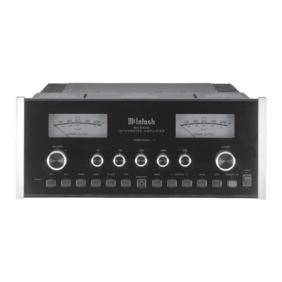
Page 12: Front Panel Controls, Display, Indicator Push-Button And Switch
Select any one MONO push-button MUTE push-button STANDBY/ON of the six Audio combines the left and mutes the listening push-button turns signal sources right channel signals for audio the MA6900 ON, Mono operation or OFF (Standby) -
Page 13: How To Operate
PH/AUX inputs, set indicate the MA6900 is in Standby the PH AUX switch to the PH position. mode. To turn On the MA6900, press When using an auxiliary program source the STANDBY/ON push-button. The component connected to the PH/AUX... - Page 14 Reset of Microprocessors Note: The MA6900 TAPE OUTPUTS are not affected by the VOLUME or BALANCE controls. In the event that the controls of the MA6900 stop function- ing, push the POWER switch OFF and wait about two min- Power Output Meters utes.
- Page 15 Notes...
-
Page 16: Remote Control Push-Buttons
Remote Control Push-Buttons Press to Power the LED illuminates during the Press MODE to switch between MA6900 ON or OFF time a remote command is Stereo or Mono Modes sent to the MA6900 Turns AC Power ON or OFF to cer-... -
Page 17: How To Operate By Remote Control
When one of the Audio/Video Inputs (SAT, Acc On LV, TV, VCR, VCR2 and DVD) are selected by remote Press ACC ON to turn the power ON to a McIntosh Disc control, the MA6900 will automatically switch to the Player. -
Page 18: Technical Description
Integrated Ampli- fier McIntosh has ever manufactured. The distortion limits for the MA6900 are no more than 0.005% at rated power output for all frequencies from 20Hz to 20,000Hz. Typical performance at mid frequencies is less than 0.002%. The true distortion readings on the MA6900 are so low, it takes special measuring techniques to make accurate readings. - Page 19 All inputs, outputs, and data ports are controlled by current amplification must be as linear as possible prior to logic circuits in the MA6900. The logic is changed by front the use of negative feedback. McIntosh engineers know panel push-buttons or by a microprocessor IR decoder.
- Page 20 Re- tributes to low operating temperatures. More than 621 fer to figures 14, 15 and 16. An square inches of heat sink area keep the MA6900 operating overdriven amplifier can pro- safely with convection cooling. No fans are needed.
- Page 21 Power Supply Circuits With Power Guard tronic attenuator at the amplifier To compliment the design of the MA6900, there is a high input reduces the input volume voltage power supply for both channels. Refer to figure 17. just enough to prevent any fur- The power amplifiers draw high current from the AC ther increase in distortion.
-
Page 22: Specifications
230 Volts, 50/60Hz at 2.35 Amps Frequency Response 240 Volts, 50/60Hz at 2.25 Amps +0, -0.5dB from 20Hz to 20,000Hz Note: Refer to the rear panel of the MA6900 for the correct +0, -3dB from 10Hz to 100,000Hz voltage. Sensitivity Overall Dimensions Phono, 2.5mV for 2.5V rated output (0.5mV IHF) -
Page 23: Packing Instruction
104033 #10 x 1-3/4 inch Flat washer or write Customer Service Department of McIntosh Labo- ratory. Please see the Part List for the correct part numbers. 017218 Plastic foot... - Page 24 McIntosh Laboratory, Inc. 2 Chambers Street Binghamton, NY 13903 The continuous improvement of its products is the policy of McIntosh Laboratory Incorporated who reserve the right to improve design without notice. Printed in the U.S.A. McIntosh Part No. 04099100...
Need help?
Do you have a question about the MA6900 and is the answer not in the manual?
Questions and answers