Advertisement
Quick Links
Advertisement

Related Manuals for McIntosh MA6200


Summary of Contents for McIntosh MA6200
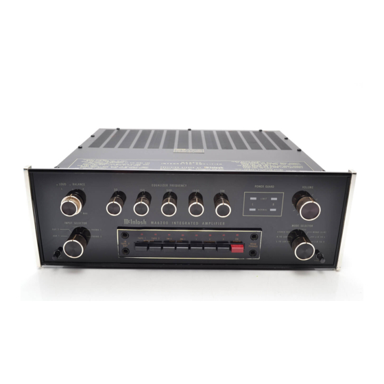
- Page 1 THE MA 6200 INTEGRATED AMPLIFIER Reading Time: 40 Minutes Price: $2.00...
- Page 2 VARIOUS REGULATORY AGENCIES REQUIRE THAT WE BRING THE FOLLOWING INFOR- MATION TO YOUR ATTENTION. PLEASE READ IT CAREFULLY. WARNING: TO PREVENT FIRE OR SHOCK HAZARD, DO NOT EXPOSE THIS UNIT TO RAIN OR MOISTURE. The Mclntosh you have purchased is a Model MA 6200.
-
Page 3: Table Of Contents
Your MA 6200 Integrated Amplifier will give you many years of pleasant and satisfactory performance. If you have any questions, please contact: Contents CUSTOMER SERVICE Mclntosh Laboratory Inc. 2 Chambers Street Binghamton, New York 13903-9990 HOW TO I N S T A L L . . . 2 HOW TO CONNECT... -
Page 4: How To I N S T A L L
The recommended minimum space for installation is 15 inches (38.1 cm) deep, 17 inches (43.2 cm) wide, and 6 inches (15.2 cm) high. To install the instrument in a Mclntosh cabinet, follow the instructions that are enclosed with the cabinet. For any other type of installation follow these instructions: 1. - Page 5 Install Mounting Strips In the hardware package you will find two mounting strips and two sets of machine screws. For panels that are less than ½ inch thick, use the ¾ inch screws; for panels that are more than ½ inch thick, use the 1¼...
-
Page 6: How To Connect
How to Connect CONNECTING TURNTABLE TO PHONO 1 AND 2 Connect a cable from the L TAPE 1 OUTPUT jack Connect the cable from the "left" channel of the to the left high level input of the tape recorder. Con- turntable into the L PHONO 1 INPUT jack. - Page 8 turntable on/off switch. When AC power to the turn- Connect the leads from the left main loudspeaker table is turned on, automatically the instrument and to the SPEAKER 1 Left and Common push connec- tors. Connect the lead from the right main the SWITCHED black AC power outlets are turned on.
-
Page 10: The Front Panel Controls And How To Use Them
The Front Panel Controls and How to use Them INPUT SELECTOR response has been shaped according to the RIAA The INPUT SELECTOR Is a five position switch standard to compensate for the characteristics of a that connects the chosen input program to the pro- magnetic phono cartridge. - Page 11 STEREO REV: Connects the left program to the Frequency response is flat and there is no right loudspeaker and the right program to the left loudness compensation when the knob is turned ful- loudspeaker. ly counter-clockwise to the "flat" position. STEREO: Connects the left program to the left loudspeaker and the right program to the right EQUALIZER FREQUENCY CONTROLS...
- Page 12 The MA 6200 is designed so it may be used with nected. A metal shielded 1/4 inch stereo phone plug two tape recorders. The four left pushbuttons con- is used for best shielding. Connections follow the in- trol the signal output of these recorders. They permit dustry standards and are tip: left signal, ring: right recordings to be monitored as they are being record- signal, and sleeve: common ground.
- Page 13 of power when they are driven to clipping and can have more than 40% harmonic distortion. The extra energy content of the clipped signal will damage most speak- ers. A Mclntosh ad- vancement helps to protect your speaker from this kind of damage. The MA 6200 has a built in "waveform comparator"...
-
Page 14: Performance Limits
Performance Limits We promise you that the MA 6200 you buy must be Tape & Aux Input: 100 dBA, 95 dB unweighted, capable of performance at or exceeding these limits below rated output at the time of purchase or you get your money back. Phono Input: 85 dBA, 80 dB unweighted, Mclntosh PERFORMANCE LIMITS are the maximum... -
Page 15: Performance Charts
Performance Charts POWER OUTPUT SECTION HARMONIC DISTORTION VS POWER RL = 8 OHMS, BOTH CHANNELS OPERATING POWER OUTPUT IN WATTS POWER OUTPUT SECTION BOTH CHANNELS OPERATING .05% THD POWER BANDWIDTH 100k FREQUENCY Hz OUTPUT SIGNAL WAVEFORM SHOWING ACTION OF POWER GUARD TO ELIMINATE OUTPUT SIGNAL INTERMODULATION DISTORTION CLIPPING. - Page 16 LOUDNESS RESPONSE FREQUENCY IN HERTZ FREQUENCY RESPONSE OF EQUALIZER FREQUENCY CONTROLS SET AT MAXIMUM AND MINIMUM FREQUENCY IN HERTZ PHONO EQUALIZATION (RIAA) RESPONSE FREQUENCY IN HERTZ...
-
Page 17: Technical Description
Technical Description Munson equal loudness compensation. A poten- AUDIO SECTION Each channel of the MA 6200 has four basic sec- tiometer is placed between these two feedback loops making it possible to select any combination tions. They are: phono preamplifier, high level and loudness amplifier, equalizer amplifier, and power of the two from a flat response to full loudness com- pensation. - Page 18 conditions. To further insure reliability a special occurs when an amplifier is asked to exceed its power output SENTRY MONITORING CIRCUIT design limits and the capacity of the power supply. prevents failure of the power amplifier transistors Since POWER GUARD does not begin to work until due to excessive mismatch or shorting of the output.
- Page 20 MclNTOSH LABORATORY INC. 2 CHAMBERS ST., BINGHAMTON, N.Y. 13903-2699 607-723-3512 The continuous improvement of its products is the policy of Mclntosh Laboratory Incorporated who reserve the right to improve design without notice. Printed in U.S.A. 039179 BE032003...
Need help?
Do you have a question about the MA6200 and is the answer not in the manual?
Questions and answers