McIntosh MA7000 Owner's Manual
Mcintosh owner's manual integrated amplifier ma7000
Hide thumbs
Also See for MA7000:
- Service manual (36 pages) ,
- Connection diagrams (2 pages) ,
- Programming manual (21 pages)

Related Manuals for McIntosh MA7000


Summary of Contents for McIntosh MA7000
-
Page 1: Integrated Amplifier
Integrated Amplifier MA7000 Owner’s Manual McIntosh Laboratory, Inc. 2 Chambers Street Binghamton, New York 13903-2699 Phone: 607-723-3512 FAX: 607-724-0549... -
Page 2: Important Safety Instructions
The lightning flash with arrowhead, within an equilateral triangle, is intended to alert the user to the presence of uninsulated “danger- ous voltage” within the product’s enclosure that may be of sufficient magnitude to constitute a risk of electric shock to persons. WARNING - TO REDUCE RISK OF FIRE OR ELECTRICAL SHOCK, DO NOT EXPOSE THIS EQUIPMENT TO... -
Page 3: Table Of Contents
Phone: 607-723-1545 Fax: 607-724-0549 Customer Service If it is determined that your McIntosh product is in need of repair, you can return it to your Dealer. You can also return it to the McIntosh Laboratory Service Department. For assistance on factory repair return procedure, contact the McIntosh Service Department at: McIntosh Laboratory, Inc. -
Page 4: Connector And Cable Information
Connector and Cable Information XLR Connectors Below is the Pin configuration for the XLR Balanced Input and Output Connectors on the MA7000. Refer to the dia- gram for connection: PIN 1: Shield/Ground PIN 2: + Output PIN 3: - Output... -
Page 5: Dimensions
Dimensions The following dimensions can assist in determining the best location for your MA7000. There is additional in- formation on the next page pertaining to installing the MA7000 into cabinets. Front View of the MA7000 Rear View of the MA7000 "... -
Page 6: Installation
Installation The MA7000 can be placed upright on a table or shelf, standing on its four feet. It also can be custom installed in a piece of furniture or cabinet of your choice. The four feet may be removed from the bottom of the MA7000 when it is custom installed as outlined below. -
Page 7: Rear Panel Connections
Rear Panel Connections Connect the MA7000 power cord to a live AC outlet. Refer to information on the back panel of your MA7000 to determine the correct voltage for your unit... -
Page 8: Connecting Components
Remote Control. With an external sensor connected to the MA7000, remote control operation of the system is possi- ble from another room and/or when the MA7000 is located in a cabinet with the doors closed. The connection instructions below, together with the MA7000 Input and Output Connection Diagrams located on the separate folded sheet “Mc1A/1B”, are an example of... -
Page 9: How To Connect
Loudspeaker’s impedance is in-between the available connections, use the nearest lower impedance connec- tion. Figure 2 Figure 3 4. Connect the MA7000 Power Cord to a live AC outlet. How to Connect Figure 4 Figure 5 out. Refer to figures 4, 5 & 6. -
Page 10: Remote Control Push-Buttons
Selects one of the seven available Audio Sources Remote Control Push-Buttons Press to Power the MA7000 ON or OFF... -
Page 11: How To Use The Remote Control
How to use the Remote Control The supplied Remote Control is capable of directly con- trolling the functions of contemporary McIntosh Source Components connected to the MA7000 via the Data Ports. Input Source Selection Press the appropriate Source Push-button to select the desired program source. -
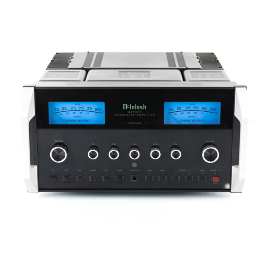
Page 12: Front Panel Displays, Controls, Push-Buttons And Jack
IR Sensor receives commands from a Remote Control Front Panel Displays, Controls, Push-buttons and Jack Standby Power On Indicator STANDBY/ON Push-button switch- es the MA7000 ON or OFF (Standby) and resets the micro- processors... -
Page 13: How To Operate The Ma7000
How to Operate the MA7000 Power On The Red LED above the STANDBY/ON Push-button lights to indicate the MA7000 is in Standby mode. To Switch ON the MA7000, press the STANDBY/ON Push-button on the Front Panel or the Power Push-button on the Remote Control. -
Page 14: How To Operate The Ma7000
Using a Separate Power Amplifier There are two different ways to use a separate power am- plifier with a MA7000. The first way is to use the separate amplifier instead of the MA7000 built-in Power Amplifier. Connect the Loudspeakers to the separate power amplifier and remove the McIntosh Jumpers that are located between the OUTPUTS 1 Jacks and the POWER AMP INput Jacks. -
Page 15: Technical Description
Integrated Ampli- fier McIntosh has ever manufactured. The distortion limits for the MA7000 are no more than 0.005% at rated power output for all frequencies from 20Hz to 20,000Hz. Typical performance at mid frequencies is less than 0.002%. The true distortion readings on the MA7000 are so low, it takes special measuring techniques to make accurate readings. - Page 16 All inputs, outputs, and data ports are controlled by logic circuits in the MA7000. The logic is changed by front panel push-buttons or by a microprocessor IR de- coder. This microprocessor IR decoder is programmed with exclusive McIntosh software.
-
Page 17: Protection Circuits
The different types of protec- tion circuits incorporated in the MA7000 insure a long and safe operating life. The MA7000 also includes the unique patented McIn- tosh Power Guard circuit. Power Guard eliminates the pos- sibility of ever overdriving the ampli- fier into clipping. -
Page 18: Specifications
220 Volts, 50/60Hz at 3.3 amps 230 Volts, 50/60Hz at 3.3 amps 240 Volts, 50/60Hz at 3.3 amps Standby: Less than 1 watt Note: Refer to the rear panel of the MA7000 for the correct voltage. Overall Dimensions Width is 17-1/2 inches (44.45cm) Height is 9-7/16 inches (23.97cm) including feet... -
Page 19: Packing Instruction
If a shipping carton or any of the interior part(s) are needed, please call or write Customer Service Department of McIntosh Laboratory. Refer to page 3. Please see the Part List for the correct part numbers. - Page 20 McIntosh Laboratory, Inc. 2 Chambers Street Binghamton, NY 13903 The continuous improvement of its products is the policy of McIntosh Laboratory Incorporated who reserve the right to improve design without notice. Printed in the U.S.A. McIntosh Part No. 04105200...
Need help?
Do you have a question about the MA7000 and is the answer not in the manual?
Questions and answers