Table of Contents
Advertisement
Quick Links
INVERTER
CC2
FR-CC2-P (CONVERTER UNIT FOR PARALLEL OPERATION)
INSTRUCTION MANUAL
Converter Unit
FR-CC2-H400K to H560K-P
INTRODUCTION
INSTALLATION AND WIRING
PRECAUTIONS FOR USE OF
THE CONVERTER UNIT
BASIC OPERATION
PARAMETER
PROTECTIVE FUNCTIONS
PRECAUTIONS FOR MAINTE-
NANCE AND INSPECTION
SPECIFICATIONS
1
2
3
4
5
6
7
8
Advertisement
Chapters
Table of Contents

Related Manuals for Mitsubishi Electric FR-CC2-P


Summary of Contents for Mitsubishi Electric FR-CC2-P
- Page 1 INVERTER FR-CC2-P (CONVERTER UNIT FOR PARALLEL OPERATION) INSTRUCTION MANUAL Converter Unit FR-CC2-H400K to H560K-P INTRODUCTION INSTALLATION AND WIRING PRECAUTIONS FOR USE OF THE CONVERTER UNIT BASIC OPERATION PARAMETER PROTECTIVE FUNCTIONS PRECAUTIONS FOR MAINTE- NANCE AND INSPECTION SPECIFICATIONS...
- Page 2 Thank you for choosing this Mitsubishi Electric converter unit. This Instruction Manual provides handling information and precautions for use of the FR-CC2-P series. Incorrect handling might cause an unexpected fault. Before using this converter unit, always read this Instruction Manual carefully to use this product correctly.
- Page 3 CAUTION CAUTION Transportation and installation Usage The storage temperature (applicable for a short time, e.g. during Do not repeatedly start or stop the inverter with a magnetic transit) must be between -20 and +65°C. Otherwise the contactor on its input side. Doing so may shorten the life of the converter unit may be damaged.
- Page 4 CONTENTS 1 INTRODUCTION Product checking Component names Related manuals 2 INSTALLATION AND WIRING Peripheral devices 2.1.1 Converter unit and peripheral devices ......................12 2.1.2 Peripheral device ............................13 Removal and reinstallation of the front cover Installation of the converter unit and enclosure design 2.3.1 Converter unit installation environment ......................20 2.3.2...
- Page 5 3 PRECAUTIONS FOR USE OF THE CONVERTER UNIT Electro-magnetic interference (EMI) and leakage currents 3.1.1 Leakage currents and countermeasures......................60 3.1.2 Countermeasures against EMI generated by the inverter or the converter unit..........62 3.1.3 Built-in EMC filter............................65 Power supply harmonics 3.2.1 Power supply harmonics ..........................
- Page 6 (M) Monitor display and monitor output signal 5.4.1 Monitor display selection using operation panel or via communication ............101 5.4.2 Output terminal function selection ........................105 5.4.3 Detection of control circuit temperature ......................108 (T) Multi-function input terminal parameters 5.5.1 Input terminal function selection ........................109 5.5.2 Operation selection for the external thermal relay input (Pr.876) ..............110 (A) Application parameters...
-
Page 7: Table Of Contents
Inspection item 7.1.1 Daily inspection ............................154 7.1.2 Periodic inspection ............................154 7.1.3 Daily and periodic inspection........................155 7.1.4 Checking the converter semiconductor devices................... 157 7.1.5 Cleaning ............................... 157 7.1.6 Replacement of parts ........................... 158 7.1.7 Converter unit replacement .......................... 160 Measurement of main circuit voltages, currents and powers 7.2.1 Measurement of powers.......................... - Page 8 ...............10 <Abbreviations> Operation panel ..Operation panel of the inverter (FR-DU08) Converter unit ..Converter unit FR-CC2-P series (for parallel operation) Inverter..... Mitsubishi Electric FR-A802-P series inverter (separated converter type for parallel operation) Pr......Parameter number (Number assigned to function) <Trademarks>...
- Page 9 Product checking Product checking Unpack the product and check the rating plate and the capacity plate of the converter unit to ensure that the model agrees is as ordered and the product is intact. Converter unit model Symbol Description Symbol Function Symbol Voltage class 400V class...
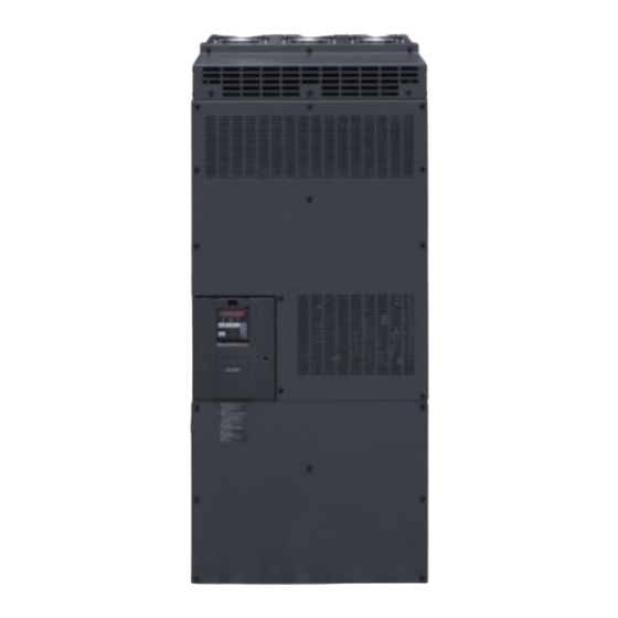
- Page 10 Component names Component names Component names are shown below. Refer to Symbol Name Description page Connects the operation panel. This connector also enables the RS-485 PU connector communication. For manufacturer setting. Do not use. Enable RS-485 communication between the master and the slave for the parallel RS-485 terminals operation.
- Page 11 Related manuals Related manuals Manuals related to the FR-CC2-P converter unit are shown in the following table. Name Manual number FR-A802-P Instruction Manual (Hardware) IB-0600651ENG Parallel Operation Function Manual IB-0600654ENG FR-A800 Instruction Manual (Detailed) IB-0600503ENG INTRODUCTION...
- Page 12 INSTALLATION AND WIRING This chapter explains the "installation" and the "wiring" of this product. Always read the instructions before using the equipment. 2.1 Peripheral devices ..............12 2.2 Removal and reinstallation of the front cover......18 2.3 Installation of the converter unit and enclosure design ..20 2.4 Terminal connection diagrams ..........27...
-
Page 13: Peripheral Devices
(MCCB) or earth leakage contactor current breaker (ELB), fuse (MC) (f) Noise filter R/L1 S/L2 T/L3 (g) Noise filter (b) Converter unit (a) Inverter (FR-CC2-P) (FR-A802-P) Earth (Ground) Earth (Ground) (h) Induction motor Earth (Ground) R/L1 S/L2 T/L3 (g) Noise filter... - Page 14 Incorrect wiring may lead to damage of the inverter and the converter unit. The control signal lines must be kept fully away from the main circuit lines Converter unit (FR-CC2-P) to protect them from noise. The built-in EMC filter of the converter unit can reduce the noise.
- Page 15 Peripheral devices Selecting the breaker/magnetic contactor 6-phase transformer Check the model of the inverter and the converter unit you purchased. Appropriate peripheral devices must be selected according to the capacity. Refer to the table below to prepare appropriate peripheral devices. •...
- Page 16 • Option 1 To connect the equipment to the input side of the 12-phase rectifier transformer before branching, prepare the same equipment as for the 6-phase rectifier transformer (refer to the FR-CC2-P Instruction Manual). • Option 2 To connect the equipment to the output side of the 12-phase rectifier transformer before branching, refer to the following table and prepare appropriate equipment.
- Page 17 Peripheral devices control Number of Applicable Rated input current Molded case circuit breaker Magnetic contactor units in converter unit for one circuit (MCCB) (NF type) (MC) on converter parallel FR-CC2-[ ]-P unit's input side H400K 1000 900 A rated product H450K 1200 1000 A rated product...
- Page 18 Peripheral devices NOTE • When the converter unit capacity is larger than the motor capacity, select an MCCB and an MC (magnetic contactor) according to the converter unit model, and select cables and reactors according to the motor output. • When the breaker on the converter unit's input side trips, check for the wiring fault (short circuit), damage to internal parts of the inverter or the converter unit, etc.
-
Page 19: Removal And Reinstallation Of The Front
Removal and reinstallation of the front cover Removal and reinstallation of the front cover Removal of the accessory cover and installation of the operation panel • Loosen the two fixing screws on the accessory cover. • Push the upper edge of the accessory cover and pull the (These screws cannot be removed.) accessory cover to remove. - Page 20 Removal and reinstallation of the front cover Removal of the front cover (upper side) Loosen Loosen Loosen With the front cover (lower side) removed, loosen the mounting screws on the front cover (upper side). (These screws cannot be removed.) While holding the areas around the installation hooks on the sides of the front cover (upper side), pull out the front cover (upper side) using its upper side as a support.
-
Page 21: Installation Of The Converter Unit And Enclosure Design
Installation of the converter unit and enclosure design Installation of the converter unit and enclosure design When designing or manufacturing an enclosure to contain the converter unit, determine the structure, size, and device layout of the enclosure by fully considering the conditions such as heat generation of the contained devices and the operating environment. - Page 22 Installation of the converter unit and enclosure design (a) Measures against high humidity • Make the enclosure enclosed, and provide it with a hygroscopic agent. • Provide dry air into the enclosure from outside. • Provide a space heater in the enclosure. (b) Measures against low humidity Air with proper humidity can be blown into the enclosure from outside.
- Page 23 Installation of the converter unit and enclosure design 2.3.2 Cooling system types for converter unit enclosure From the enclosure that contains the converter unit, the heat of the converter unit and other equipment (transformers, lamps, resistors, etc.) and the incoming heat such as direct sunlight must be dissipated to keep the in-enclosure temperature lower than the permissible temperatures of the in-enclosure equipment including the converter unit.
- Page 24 Installation of the converter unit and enclosure design 2.3.3 Installation of the converter unit Installation of the converter unit Fix six positions. • Install the converter unit on a strong surface securely with screws. • Leave enough clearances and take cooling measures. •...
- Page 25 Installation of the converter unit and enclosure design Encasing multiple inverters and converter units When multiple inverters and converter units are placed in the same enclosure, generally arrange them horizontally as shown in the figure on the right. Do not place multiple converter units or the Converter Converter Inverter...
- Page 26 Installation of the converter unit and enclosure design 2.3.4 Protruding the heat sink When encasing an converter unit to an enclosure, the heat generated in the enclosure can be greatly reduced by protruding the heat sink of the converter unit. When installing the converter unit in a compact enclosure, etc., this installation method is recommended.
- Page 27 Installation of the converter unit and enclosure design Shift and removal of a rear side installation frame One installation frame is attached to each of the upper and lower parts of the converter unit. Remove the rear side installation frame Upper on the top and bottom sides of the converter unit as shown on the installation...
-
Page 28: Terminal Connection Diagrams
Terminal connection diagrams Terminal connection diagrams When the sink logic is selected Sink logic Main circuit terminal Control circuit terminal Inverter MCCB DC reactor Inrush current R/L1 Three-phase limit circuit S/L2 AC power T/L3 supply EMC filter R1/L11 ON/OFF Jumper S1/L21 ∗1 connecter... - Page 29 Terminal connection diagrams When the source logic is selected Source logic Main circuit terminal Inverter Control circuit terminal MCCB DC reactor Inrush current R/L1 Three-phase limit circuit S/L2 AC power T/L3 supply EMC filter ON/OFF R1/L11 Jumper connecter S1/L21 ∗1 Main circuit Earth (Ground)
- Page 30 Terminal connection diagrams System configuration example (for operating two units in parallel) • Wire the RS-485 terminals between the converter units as shown in the diagram in page 30. (For the details on wiring the RS-485 terminals, refer to page 53.) •...
- Page 31 Terminal connection diagrams • Terminal connection diagram for two units in parallel (for driving a single wound motor) FR-CC2-P (master) FR-A802-P (master) FR-POL R/L1 Three-phase AC power S/L2 supply T/L3 R1/L11 R1/L11 S1/L21 S1/L21 MRS(X10) TXD1+ TXD1+ TXD1- TXD1- TXD2+...
- Page 32 Terminal connection diagrams • Terminal connection diagram for two units in parallel (for driving a multi-wound motor) FR-CC2-P (master) FR-A802-P (master) R/L1 Three-phase AC power S/L2 T/L3 supply R1/L11 R1/L11 S1/L21 S1/L21 MRS(X10) TXD1+ TXD1+ TXD1- TXD1- TXD2+ TXD2+ TXD2-...
- Page 33 Terminal connection diagrams System configuration example (for operating three units in parallel) • Wire the RS-485 terminals between the converter units as shown in the diagram in page 33. (For the details on wiring the RS-485 terminals, refer to page 53.) •...
- Page 34 TXD1- TXD1- TXD2+ TXD2+ TXD2- TXD2- RXD1+ RXD1+ RXD1- RXD1- RXD2+ RXD2+ RXD2- RXD2- GND(SG) GND(SG) GND(SG) GND(SG) FR-CC2-P (slave 1) FR-A802-P (slave 1) FR-POL R/L1 S/L2 T/L3 R1/L11 R1/L11 S1/L21 S1/L21 TXD1+ TXD1+ TXD1- TXD1- TXD2+ TXD2+ TXD2- TXD2-...
- Page 35 Terminal connection diagrams Wiring converter units and inverters Main circuit terminals • Wire the converter unit to the inverter at each terminal P and terminal N. Pair the masters or the slaves (1 with 1 or 2.with 2). Otherwise, incorrect connection may damage the converter unit and the inverter. •...
- Page 36 Main circuit terminals (6-phase rectification) Main circuit terminals (6-phase rectification) 2.5.1 Details on the main circuit terminals Terminal Refer to Terminal name Terminal function description symbol page R/L1, S/L2, AC power input Connect these terminals to the commercial power supply. —...
- Page 37 Main circuit terminals (6-phase rectification) NOTE • Make sure the power cables are connected to the R/L1, S/L2, and T/L3. (Phase need not be matched.) • When wiring the main circuit conductor, tighten a nut from the right side of the conductor. When wiring two wires, place wires on both sides of the conductor.
- Page 38 Main circuit terminals (6-phase rectification) 2.5.3 Applicable cables Select a recommended cable size to ensure that the voltage drop will be 2% or less. The following table indicates a selection example for the wiring length of 20 m per converter unit. (440 V input power supply, 150% overload current rating for 1 minute).
- Page 39 Main circuit terminals (6-phase rectification) 2.5.4 Earthing (grounding) precautions • Always earth (ground) the converter unit. Purpose of earthing (grounding) Generally, an electrical apparatus has an earth (ground) terminal, which must be connected to the ground before use. An electrical circuit is usually insulated by an insulating material and encased. However, it is impossible to manufacture an insulating material that can shut off a leakage current completely, and actually, a slight current flows into the case.
- Page 40 Main circuit terminals (for 12-phase rectification) Main circuit terminals (for 12-phase rectification) 2.6.1 Details on the main circuit terminals Refer to Terminal symbol Terminal name Terminal function description page Connect these terminals to the output terminals in the wye R/L1, S/L2, T/L3 AC power input connection of a 12-phase transformer (3-winding transformer).
- Page 41 Main circuit terminals (for 12-phase rectification) 2.6.4 Wiring method • In the initial status, terminals R/L1 and R2/L12, S/L2 and S2/L22, and T/L3 and T2/L32 of the converter unit are respectively shorted with shorting conductors. For 12-phase rectification, remove the bolts and nuts shown in the figure below to remove the shorting conductors.
- Page 42 Main circuit terminals (for 12-phase rectification) • When wiring cables to the main circuit conductor, tighten each nut from the right of the conductor as seen from the front of the unit. When wiring two cables, place cables on both sides of the conductor. Use the bolts and nuts removed earlier for these connections.
- Page 43 Main circuit terminals (for 12-phase rectification) NOTE • Tighten the terminal screw to the specified torque. A screw that has been tightened too loosely can cause a short circuit or malfunction. A screw that has been tightened too tightly can cause a short circuit or malfunction due to the unit breakage. •...
- Page 44 Control circuit Control circuit 2.7.1 Details on the control circuit terminals The input signal function of the terminals in can be selected by setting Pr.178, Pr.187, Pr.189 to Pr.195 (I/O terminal function selection). (Refer to page 105, 109.) Input signal Terminal Terminal name Terminal function description...
- Page 45 Control circuit Output signal Terminal Terminal name Terminal function description Rate Specification Symbol 1 changeover contact output that indicates that the protective function of Contact capacity 230 Relay output 1 (fault the converter unit has been activated and the outputs are stopped. VAC 0.3 A (power output) Fault: discontinuity across B and C (continuity across A and C), Normal:...
- Page 46 Control circuit 2.7.2 Control logic (sink/source) change Change the control logic of input signals as necessary. To change the control logic, change the jumper connector position on the control circuit board. Connect the jumper connector to the connector pin of the desired control logic. The jumper connector is in the sink logic (SINK) when shipped from the factory.
- Page 47 Control circuit Sink logic and source logic • In the sink logic, a signal switches ON when a current flows from the corresponding signal input terminal. Terminal SD is common to the contact input signals. Terminal SE is common to the open collector output signals. •...
- Page 48 Control circuit 2.7.3 Wiring of control circuit Control circuit terminal layout ∗1 ∗1 NC NC NC NC NC +24 SD NC NC NC NC PC NC NC NC SE SE IPF RSO FAN PC NC NC NC NC NC NC OH SD SD RDI NC NC ...
- Page 49 Control circuit Ferrule terminal model Crimping tool Cable gauge (mm name With insulation sleeve Without insulation sleeve For UL wire A ferrule terminal with an insulation sleeve compatible with the MTW wire which has a thick wire insulation. ...
- Page 50 Control circuit Signal inputs by contactless switches The contact input terminals of the converter unit (RES, OH, RDI) can be controlled using a transistor instead of a contact switch as shown below. +24 V Converter unit +24 V RDI, etc Converter unit RDI, etc External signal input using transistor...
- Page 51 Control circuit 2.7.5 When using separate power supplies for the control circuit and the main circuit Cable size for the control circuit power supply (terminals R1/L11 and S1/ L21) • Terminal screw size: M4 • Cable gauge: 0.75 mm to 2 mm •...
- Page 52 Control circuit 2.7.6 When supplying 24 V external power to the control circuit Connect a 24 V external power supply across terminals +24 and SD. Connecting a 24 V external power supply enables I/O terminal ON/OFF operation, operation panel displays, control functions, and communication during communication operation even during power-OFF of converter unit's main circuit power supply.
- Page 53 Control circuit Operation while the 24 V external power is supplied • Fault history and parameters can be read and parameters can be written using the operation panel keys. • During the 24 V external power supply operation, monitored items and signals related to inputs to main circuit power supply, such as input current and converter output voltage are invalid.
- Page 54 Communication connectors and terminals Communication connectors and terminals 2.8.1 RS-485 terminal block Connecting the RS-485 terminals of the master/slave converter units enables communication for parallel operation. RS-485 terminal layout Terminating resistor switch Name Description Initially-set to "OPEN". RXD1+ Converter unit receive+ Set only the terminating resistor switch of RXD1- Converter unit receive-...
- Page 55 Communication connectors and terminals RS-485 terminal wiring method • Operating two converter units in parallel Ferrite cores ∗1 Master Slave • Operating three converter units in parallel Ferrite cores Ferrite cores ∗1 Master Slave 1 Slave 2 Set the terminating resistor switch to 100 . NOTE •...
- Page 56 Communication connectors and terminals 2.8.2 PU connector Installing the operation panel on the enclosure surface • Having an operation panel on the enclosure surface is convenient. With a connection cable, you can install the operation panel on the enclosure surface, and connect it to the converter unit. Use the option FR-CB2[ ], or connectors and cables available on the market.
- Page 57 Setting parameters for parallel operation Setting parameters for parallel operation Parallel operation selection (Pr.1001) Description Name Initial value Setting range Master/slave station Number of slave station Slave station 1 — Slave station 2 — 1001 Parallel operation 100 (initial value) E390 selection Master station...
- Page 58 Setting parameters for parallel operation Parallel operation communication check time (Pr.652) Name Initial value Setting range Description Parallel operation communication disabled Set the interval of the communication check Parallel operation (signal loss detection) time. 0.1 to 120 s N092 communication check time If a no-communication state persists for the permissible time or longer, the inverter will trip.
- Page 59 MEMO...
- Page 60 PRECAUTIONS FOR USE OF THE CONVERTER UNIT This chapter explains the precautions for use of this product. Always read the instructions before using the equipment. 3.1 Electro-magnetic interference (EMI) and leakage currents ..60 3.2 Power supply harmonics ............66 3.3 Power-OFF and magnetic contactor (MC) ......70 3.4 Checklist before starting operation ........71...
-
Page 61: Electro-Magnetic Interference (Emi) And Leakage Currents
Electro-magnetic interference (EMI) and leakage currents Electro-magnetic interference (EMI) and leakage currents 3.1.1 Leakage currents and countermeasures Capacitances exist between the I/O cables or other cables of the inverter or the converter unit and earth, and in the motor, through which a leakage current flows. The amount of current leakage depends on the size of the capacitance. Take the following precautions to prevent current leakage. - Page 62 • Leakage currents of the inverter and the converter unit with a 6-phase transformer 400 V class (input power condition: 440 V/60 Hz, power supply unbalance within 3%) Inverter/ FR-A802-P Converter unit converter unit (Separated converter type) FR-CC2-P EMC filter Phase earthing (grounding) Earthed-neutral system (mA) •...
- Page 63 Electro-magnetic interference (EMI) and leakage currents 400 V class (input power condition: 440 V/60 Hz, power supply unbalance within 3%) EMC filter Wye connection / Delta connection (mA) NOTE • Install the earth leakage circuit breaker (ELB) on the input side of the converter unit. •...
- Page 64 Electro-magnetic interference (EMI) and leakage currents • Techniques to reduce electromagnetic noises that are radiated by the inverter or the converter unit to cause the peripheral devices to malfunction (EMI countermeasures) Noises generated from the inverter or the converter unit are largely classified into those radiated by the cables connected to the inverter or the converter unit and their main circuits (I/O), those electromagnetically and electrostatically induced to the signal cables of the peripheral devices close to the main circuit cables, and those transmitted through the power supply cables.
- Page 65 Electro-magnetic interference (EMI) and leakage currents Data line filter Data line filter is effective as an EMI countermeasure. Provide a data line filter for the detector cable, etc. <Example> Data line filter : ZCAT3035-1330 (by TDK) : ESD-SR-250 (by NEC TOKIN) Impedance (ZCAT3035-1330) Impedance () [Unit: mm]...
- Page 66 Electro-magnetic interference (EMI) and leakage currents 3.1.3 Built-in EMC filter The converter unit is equipped with a built-in EMC filter (capacitive filter). The filter is effective in reducing air-propagated noise on the input side of the converter unit. Two EMC filter ON/OFF connectors are provided. Both connectors are initially set to the "disabled" (OFF) position. To enable the EMC filters, fit both of the EMC filter ON/OFF connectors to the "enabled"...
-
Page 67: Power Supply Harmonics
Power supply harmonics Power supply harmonics 3.2.1 Power supply harmonics The inverter or the converter unit may generate power supply harmonics from its converter circuit to affect the power generator, power factor correction capacitor etc. Power supply harmonics are different from noise and leakage currents in source, frequency band and transmission path. - Page 68 Power supply harmonics 3.2.2 Harmonic Suppression Guidelines Harmonic currents flow from the inverter or the converter unit to a power receiving point via a power transformer. The Harmonic Suppression Guidelines was established to protect other consumers from these outgoing harmonic currents. The three-phase 200 V input specifications 3.7 kW or lower were previously covered by "the Harmonic Suppression Guidelines for Household Appliances and General-purpose Products"...
- Page 69 Power supply harmonics • Equivalent capacity limits Received power voltage Reference capacity 6.6 kV 50 kVA 22/33 kV 300 kVA 66 kV or more 2000 kVA • Harmonic contents for 6-phase rectification (values of the fundamental current are 100%) Reactor 11th 13th 17th...
- Page 70 Power supply harmonics Item Description Installation of power factor When used with a reactor connected in series, the power factor improving correction capacitor can absorb improving capacitor harmonic currents. Transformer multi-phase - and - combinations to provide an Use two transformers with a phase angle difference of 30° as in operation effect corresponding to 12 pulses, reducing low-degree harmonic currents.
-
Page 71: Power-Off And Magnetic Contactor (Mc)
Power-OFF and magnetic contactor (MC) Power-OFF and magnetic contactor (MC) Converter unit input side magnetic contactor (MC) On the converter unit input side, it is recommended to provide an MC for the following purposes: (Refer to page 13 for selection.) •... -
Page 72: Checklist Before Starting Operation
Checklist before starting operation Checklist before starting operation The converter unit is a highly reliable product, but incorrect peripheral circuit making or operation/handling method may shorten the product life or damage the product. Before starting operation, always recheck the following points. Refer Check Checkpoint... - Page 73 MEMO...
- Page 74 BASIC OPERATION This chapter explains the "BASIC OPERATION" of this product. Always read the instructions before using the equipment. 4.1 Operation panel.................74 4.2 Monitoring the converter unit status ........78 BASIC OPERATION...
- Page 75 Operation panel Operation panel 4.1.1 Components of the operation panel Install the operation panel of the inverter on the converter unit. To mount the operation panel on the enclosure surface, refer to page Component Name Description — Not used. MON: ON to indicate the monitor mode. Quickly blinks twice intermittently while the Operation panel protective function is activated.
- Page 76 Operation panel 4.1.2 Basic operation of the operation panel Basic operation Input current monitor Electronic thermal relay function load factor monitor Converter output voltage monitor (At power-ON) The present setting displayed. Parameter setting mode Blink (Example) Value change Parameter write complete Parameter clear All parameter clear Fault history clear...
- Page 77 Operation panel Parameter setting mode In the parameter setting mode, converter unit functions (parameters) are set. The following table explains the indications in the parameter setting mode. Refer Operation panel Function name Description indication page Under this mode, the set value of the displayed parameter number is Parameter setting mode read or changed.
- Page 78 Operation panel 4.1.4 Changing the parameter setting value Changing example Change Pr.774 Operation panel monitor selection 1. Operation Screen at power-ON The monitor display appears. Parameter setting mode Press to choose the parameter setting mode. (The parameter number read previously appears.) Selecting the parameter number Turn until...
- Page 79 Monitoring the converter unit status Monitoring the converter unit status 4.2.1 Monitoring of converter output voltage and input current POINT POINT • Pressing in the monitor mode switches the monitored item to converter output voltage, input current, and then to electronic thermal relay function load factor.
- Page 80 PARAMETER This chapter explains the function setting for use of this product. Always read the instructions before using the equipment. PARAMETER...
- Page 81 Install the operation panel of the inverter on the FR-CC2-P. • The list of FR-CC2-P parameters (including the availability for the master and the slave) is as follows. indicates the parameter in which all the settings are valid. indicates the parameter in which some settings are invalid. ...
- Page 82 Parameter list Parameter list (by parameter number) Minimum Refer Initial Master Slave Customer Name Setting range setting group value station station setting increments page RDI terminal function 178 T700 9999 selection List OH terminal function 187 T709 7, 62, 84, 9999 ...
- Page 83 Parameter list Parameter list (by parameter number) Minimum Refer Initial Master Slave Customer Name Setting range setting group value station station setting increments page Control circuit temperature 663 M060 0 to 100°C 1°C 0°C signal output level 686 E712 Maintenance timer 2 0 (1 to 9998) ...
- Page 84 Parameter list Parameter display by function group 5.1.2 Parameter display by function group The monitor display can be changed to the parameter display by function group. Parameter numbers are displayed by function group. The related parameters can be set easily. List Changing to the grouped parameter numbers Pr.MD setting value...
- Page 85 Parameter list Parameter list (by function group) 5.1.3 Parameter list (by function group) (E) Environment setting (H) Protective function parameters parameters Parameters that set the converter unit operation Parameters to protect the converter unit. characteristics. Refer Name group Refer page Name H102 Undervoltage level...
- Page 86 Parameter list Parameter list (by function group) (N) Operation via communication (T) Multi-function input terminal and its settings parameters Parameters for communication operation. These parameters Parameters for the input terminals where converter unit set the communication specifications and operation. commands are received through. Refer Refer Name...
- Page 87 (E) Environment setting parameters (E) Environment setting parameters Refer to Purpose Parameter to set page To set the time Simple clock function P.E020 to P.E022 Pr.1006 to Pr.1008 To set a limit for the reset function. Reset selection / P.E100, P.E101, To shut off output if the operation disconnected PU Pr.75...
- Page 88 (E) Environment setting parameters 5.2.1 Simple clock function The time can be set. The time can only be updated while the converter unit power is ON. The real time clock function is enabled using an optional LCD operation panel (FR-LU08). Initial Name Setting range...
- Page 89 (E) Environment setting parameters 5.2.2 Reset selection / disconnected PU detection / reset limit The reset input acceptance, the disconnected operation panel connector detection function, and the reset limit function can be selected. Name Initial value Setting range Description For the initial setting, reset is always Reset selection/disconnected 14 to 17, 114 to 117 enabled, PU disconnection is not detected,...
- Page 90 (E) Environment setting parameters Reset limit function (P.E107) • Setting P.E107="1" or Pr.75 = any of "114 to 117" will make the inverter to refuse any reset operation (RES signal, etc.) for 3 minutes after the first activation of an electronic thermal function (E.THC). NOTE •...
- Page 91 (E) Environment setting parameters 5.2.5 Setting dial key lock operation selection The key operation of the operation panel can be disabled. Setting Name Initial value Description range Key lock mode disabled Key lock operation selection E200 Key lock mode enabled •...
- Page 92 (E) Environment setting parameters 5.2.7 Password function Registering a 4-digit password can restrict parameter reading/writing. Name Initial value Setting range Description Select restriction level of parameter 0 to 3, 5, 6, reading/writing when a password is Password lock level 100 to 103, 105, 106 9999 registered.
- Page 93 (E) Environment setting parameters Unlocking a password (Pr.296, Pr.297) • There are two ways of unlocking the password. • Enter the password in Pr.297. If the password matches, it unlocks. If the password does not match, an error occurs and the password does not unlock.
- Page 94 (E) Environment setting parameters 5.2.8 Free parameter Any number within the setting range of 0 to 9999 can be input. For example, these numbers can be used: • As a unit number when multiple units are used. • As a pattern number for each operation application when multiple units are used. •...
- Page 95 (E) Environment setting parameters Life alarm display and signal output (Y90 signal, Pr.255) • Whether or not the parts of the control circuit capacitor, cooling fan, or inrush current limit circuit have reached the life alarm output level can be checked with Pr.255 Life alarm status display and the life alarm signal (Y90). 0 0 0 0 0 0 0 0 0 0 0 0 1 0 0 •...
- Page 96 (E) Environment setting parameters 5.2.10 Maintenance timer alarm The maintenance timer output signal (Y95) is output when the converter unit's cumulative energization time reaches the time period set with the parameter. MT1, MT2 or MT3 is displayed on the operation panel. This can be used as a guideline for the maintenance time of peripheral devices.
- Page 97 (H) Protective function parameter (H) Protective function parameter Refer to Purpose Parameter to set page To vary the operating level of the Undervoltage level P.H102 Pr.598 undervoltage protective function To initiate an inverter protective Fault initiation P.H103 Pr.997 function To disable the I/O phase loss Input phase loss P.H201 Pr.872...
- Page 98 (H) Protective function parameter 5.3.3 Input phase loss protection selection The input phase loss protective function on the converter unit input side (R/L1, S/L2, T/L3) can be enabled or disabled. Initial Setting Name Description value range Input phase loss Without input phase loss protection H201 protection selection With input phase loss protection...
- Page 99 (H) Protective function parameter Connection diagram A connection diagram of the emergency drive is shown below. • Two units connected in parallel (for driving a single wound motor) FR-CC2-P (master) FR-A802-P (master) FR-POL MCCB Three-phase R/L1 AC power S/L2 supply...
- Page 100 (H) Protective function parameter Emergency drive operation selection (Pr.523) Use Pr.523 Emergency drive mode selection to select the emergency drive operation. Pr.523 setting Description When a critical fault occurs, the RDA signal is turned OFF and the RDB signal is turned ON to disable inverter operation.
- Page 101 (H) Protective function parameter • The fault output during emergency drive operation is as follows. Pr.190 to Pr.196 setting Signal Description Positive Negative logic logic Turns ON during emergency drive operation. Turns ON at the occurrence of a fault that causes the above-mentioned "retry" or "output shutoff"...
- Page 102 (M) Monitor display and monitor output signal (M) Monitor display and monitor output signal Refer to Purpose Parameter to set page Operation panel monitor Pr.170, Pr.268, P.M020 to P.M023, To change the monitored item on selection Pr.290, Pr.563, P.M044, the operation panel Cumulative monitor Pr.774 to Pr.776, P.M100 to P.M104...
- Page 103 Monitor item list (Pr.774 to Pr.776, Pr.992) • The monitor items of the FR-CC2-P (including the availability for the master and the slave during the parallel operation) is as follows. indicates that the monitor is valid. indicates that the monitor is invalid ("0" is displayed). Use Pr.774 to Pr.776 and Pr.992 to select a monitored item to be displayed on the operation panel.
- Page 104 (M) Monitor display and monitor output signal The total input power value of the master and slave converter units is displayed. The total cumulative power value of the master and slave converter units is displayed. While the input current of the converter unit for 12-phase rectification is monitored, a total amount of input current in the star-delta connections is shown as an effective value of input current.
- Page 105 (M) Monitor display and monitor output signal Power is measured in the range of 0 to 99999.99 kWh, and displayed in five digits. When the monitor value exceeds "999.99", a carry occurs, for example "1000.0", so the value is displayed in 0.1 kWh increments. •...
- Page 106 (M) Monitor display and monitor output signal 5.4.2 Output terminal function selection Use the following parameters to change the functions of the open collector output terminals and relay output terminals. Initial Name Initial signal Setting range value RDB terminal RDB (Inverter operation M400 function selection enable (NC contact))
- Page 107 (M) Monitor display and monitor output signal Setting Refer Signal Related Positive Negative Function Operation name parameter logic logic page Output when an alarm (fan fault or communication 107, Alarm Pr.121 error warning) occurs. Output when the converter unit's protective function is Fault activated to stop the output (at fault occurrence).
- Page 108 (M) Monitor display and monitor output signal Fan fault output signal (FAN) • A cooling fan operates at power ON of the converter unit. If the fan stops at this time, fan operation is regarded as faulty, Fan alarm (FN) is displayed on the operation panel, and the Fan fault output (FAN) and Alarm (LF) signals are output. •...
- Page 109 (M) Monitor display and monitor output signal Fault output signals (ALM, ALM2) • The Fault (ALM, ALM2) signals are output when the converter Converter unit fault occurrence unit protective function is activated. (trip) • The ALM2 signal stays ON during the reset period after the fault occurs.
- Page 110 (T) Multi-function input terminal parameters (T) Multi-function input terminal parameters Refer to Purpose Parameter to set page To assign functions to input Input terminal function P.T700, P.T709, Pr.178, Pr.187, terminals selection P.T711 Pr.189 To change operation when the OH OH input selection P.T723 Pr.876 signal is input...
- Page 111 (T) Multi-function input terminal parameters 5.5.2 Operation selection for the external thermal relay input (Pr.876) The operation when the external thermal relay input (OH) signal is input can be changed by the Pr.876 setting. Initial Setting Name Description value range No function The converter unit output is shut off by turning OFF the OH OH input selection...
- Page 112 (A) Application parameters (A) Application parameters Refer to Purpose Parameter to set page To reduce the standby power Self power management P.A006, P.E300 Pr.30, Pr.248 Automatic restart To restart after instantaneous operation after P.A702 Pr.57 power failure instantaneous power failure Power failure time To decelerate the motor to a stop deceleration-to-stop...
- Page 113 (A) Application parameters Operation of the self power management function • This is a function to control the input side magnetic contactor (MC) with an output relay to reduce standby power. Use separate power supplies for the main circuit and the control circuit by using terminals R1/L11 or S1/L21 (refer to page and 24 V external power supply input (refer to page...
- Page 114 (A) Application parameters 5.6.2 Automatic restart after instantaneous power failure selection The converter unit can be restarted after power restoration from instantaneous power failure. Name Initial value Setting range Description Restarts the motor after power restoration Restart selection from instantaneous power failure 9999 A702 9999...
- Page 115 (A) Application parameters 5.6.3 Power failure time deceleration-to-stop function This is a function to decelerate the motor to a stop when an instantaneous power failure or undervoltage occurs. Name Initial value Setting range Description Power failure stop Power failure time deceleration-to-stop function disabled A730 selection 1, 2, 21, 22...
- Page 116 (N) Operation via communication and its settings (N) Operation via communication and its settings Refer to Purpose Parameter to set page To start operation via Initial setting of operation via P.N001 Pr.342 communication communication To operate via Initial setting of computer link communication from PU P.N020 to P.N028 Pr.117 to Pr.124...
- Page 117 (N) Operation via communication and its settings Configuration and wiring of PU connector communication system • System configuration Station 0 Station 0 Converter Computer Converter Converter Computer unit unit unit RS-232C Operation Operation connector panel panel RS-232C RS-485 connector Maximum connector connector cable...
- Page 118 (N) Operation via communication and its settings 5.7.2 EEPROM write selection during communication operation Set the action when the converter unit is performing operation via communication. Initial Setting Name Description value range Parameter values written by communication are written to Communication the EEPROM and RAM.
- Page 119 (N) Operation via communication and its settings 5.7.3 Initial settings and specifications of RS-485 communication Use the following parameters to perform required settings for the RS-485 communication between the converter unit and a personal computer. • Use the PU connector of the converter unit. •...
- Page 120 (N) Operation via communication and its settings 5.7.4 Mitsubishi inverter protocol (computer link communication) Parameter settings and monitoring are possible by using the Mitsubishi inverter protocol (computer link communication) via inverter PU connector. Communication specifications • The communication specifications are given below. Related Item Description...
- Page 121 (N) Operation via communication and its settings Communication operation presence/absence and data format types • Data communication between the computer and the converter unit is made in ASCII code (hexadecimal code). • Communication operation presence/absence and data format types are as follows. Special Converter Symbol...
- Page 122 (N) Operation via communication and its settings • Data reading format a. Communication request data from the computer to the converter unit Number of characters Format Converter unit Instruction code Sum check station No. c. Reply data from the converter unit to the computer (No data error detected) Number of characters Format Converter unit...
- Page 123 (N) Operation via communication and its settings Data definitions • Control code Signal ASCII code Description name Start Of Text (Start of data) End Of Text (End of data) Enquiry (Communication request) Acknowledge (No data error detected) Line Feed Carriage Return Negative Acknowledge (Data error detected) •...
- Page 124 (N) Operation via communication and its settings (Example 1) Instruction Station Data check code Computer Converter unit number code Binary code ASCII Code H30 H31 H45 H31 H30 H37 H41 H44 H46 H34 H30+H31+H45+H31+H31+H30+H37+H41+H44 = H1F4 ∗ When the Pr. 123 Waiting time setting "9999", create the communication request data without "waiting time"...
- Page 125 (N) Operation via communication and its settings [Formula for data transmission time] Number of data Communication specifications characters (Total number of bits) = data transmission time (s) Communication (Refer to page 120.) Refer to the following section. speed (bps) ...
- Page 126 (N) Operation via communication and its settings Retry count setting (Pr.121) • Set the permissible number of retries for data receive error occurrence. (Refer to page 123 for data receive error for retry.) • When the data receive errors occur consecutively and the number of retries exceeds the permissible number setting, a communication fault (E.PUE) occurs and the inverter output is shut off.
- Page 127 (N) Operation via communication and its settings Instructions for the program • When data from the computer has any error, the converter unit does not accept that data. Hence, in the user program, always insert a retry program for data error. •...
- Page 128 (N) Operation via communication and its settings General flowchart Port open Communication setting Timeout setting Send data processing Data setting Sum code calculation Data transmission Receive data waiting Receive data processing Data retrieval Screen display CAUTION ...
- Page 129 (N) Operation via communication and its settings Setting items and set data • After completion of parameter settings, set the instruction codes and data, then start communication from the computer to allow reading/writing of parameters and monitoring. Number of data Read/ Instruction Item...
- Page 130 (N) Operation via communication and its settings Number of data Read/ Instruction Item Data description digits write code (Format) All parameters return to initial values. Whether to clear communication parameters or not can be selected according to the data. •...
- Page 131 (N) Operation via communication and its settings Converter status monitor Instruction Item Description Example code length b0: RDB (inverter operation [Example 1] H01...Inverter operation enable signal (NC contact) ON enable signal (NC contact)) b1: Fixed to 0 b2: Fixed to 0 Converter b3: RDA (inverter operation [Example 2] H80...Fault occurrence...
- Page 132 Parameter clear / all parameter clear Parameter clear / all parameter clear POINT POINT • Set "1" to Pr.CLR Parameter clear, ALL.CL All parameter clear to initialize all parameters. (Parameters cannot be cleared when Pr.77 Parameter write selection = "1".) •...
- Page 133 Verify parameters in the converter unit and the operation panel. (Refer to page 134.) NOTE • When the destination is other than the FR-CC2-P series or when parameter copy is attempted after the parameter copy reading was stopped, "model error ( )" appears. • Refer to the parameter list on page 170 for availability of parameter copy.
- Page 134 Copying and verifying parameters Copying parameter settings read to the operation panel to the converter unit Operation Connects the operation panel to the destination converter unit. Parameter setting mode Press to choose the parameter setting mode. (The parameter number read previously appears.) Selecting the parameter number Turn (parameter copy), and press...
- Page 135 Copying and verifying parameters 5.9.2 Parameter verification • Whether the parameter settings of converter units are the same or not can be checked. Operation Copy the parameter settings of the verification source converter unit to the operation panel according to the procedure on page 132.
- Page 136 Checking parameters changed from their initial values (Initial value change list) 5.10 Checking parameters changed from their initial values (Initial value change list) Parameters changed from their initial values can be displayed. Operation Screen at power-ON The monitor display appears. Parameter setting mode Press to choose the parameter setting mode.
- Page 137 MEMO...
- Page 138 PROTECTIVE FUNCTIONS This chapter explains the "PROTECTIVE FUNCTION" that operates in this product. Always read the instructions before using the equipment. 6.1 Converter unit fault and alarm indications......138 6.2 Reset method for the protective functions......138 6.3 Check and clear of the fault history ........139 6.4 Fault history and the list of fault displays ......141...
- Page 139 Converter unit fault and alarm indications Converter unit fault and alarm indications • When the converter unit detects a fault, depending on the nature of the fault, the operation panel displays an error message or warning, or a protective function is activated to shut off the inverter output. •...
- Page 140 Check and clear of the fault history Check and clear of the fault history The operation panel stores the fault indications which appears when a protective function is activated to display the fault record for the past eight faults. (Fault history) Check for the fault history Monitor mode Parameter setting mode...
- Page 141 Check and clear of the fault history Fault history clearing procedure POINT POINT • Set Err.CL Fault history clear = "1" to clear the fault history. Operation Screen at power-ON The monitor display appears. Parameter setting mode Press to choose the parameter setting mode. (The parameter number read previously appears.) Selecting the parameter number Turn until "...
- Page 142 Fault history and the list of fault displays Fault history and the list of fault displays If the displayed message does not correspond to any of the following or if you have any other problem, contact your sales representative. Error message Operation panel Data Refer to...
- Page 143 Causes and corrective actions Causes and corrective actions Error message A message regarding operational troubles is displayed. The inverter output is not shut off. Operation panel HOLD indication Name Operation panel lock Operation lock is set. Operation other than is invalid. Description (Refer to page...
- Page 144 • Check that parameter copy to the operation panel was not interrupted by switching OFF the power or by disconnecting the operation panel. • Perform parameter copy and parameter verification between converter units of the same model (FR-CC2-P Corrective action series).
- Page 145 Causes and corrective actions Operation panel indication Name Emergency drive in operation Description Appears during emergency drive operation. Check point Emergency drive operation is performed by turning ON the X84 signal. Corrective action The display is cleared when the emergency drive operation ends. PROTECTIVE FUNCTIONS...
- Page 146 Causes and corrective actions Alarm The inverter output is not shut off when a protective function is activated. An alarm can also be output with a parameter setting. (Set "98" in Pr.190 to Pr.195 (Output terminal function selection). (Refer to page 105.) Operation panel...
- Page 147 Causes and corrective actions Operation panel E.IPF indication Name Instantaneous power failure If a power failure occurs for longer than 15 ms (this also applies to converter unit input shut-off), the instantaneous power failure protective function is activated to trip the inverter in order to prevent the control circuit from malfunctioning.
- Page 148 Causes and corrective actions Operation panel E.PA2 indication Name Parallel operation slave 2 fault Appears on the operation panel of the master at an occurrence of a slave 2 converter fault during the parallel Description operation. Appears on the master converter unit even when the RS-485 terminals are incorrectly connected. •...
- Page 149 Causes and corrective actions Operation panel E.CTE indication Name Operation panel power supply short circuit / RS-485 terminals power supply short circuit • When the power supply for the operation panel (PU connector) is shorted, the power output is shutoff and the inverter output is shut off.
- Page 150 Causes and corrective actions Operation panel E. 1 indication Name Option fault Description The inverter output is shut off if a plug-in option is disconnected while the converter unit power is ON. • Check if a plug-in option is connected. Check point •...
- Page 151 Check first when you have trouble Check first when you have trouble POINT POINT • If the cause is still unknown after every check, it is recommended to initialize the parameters (initial value) then set the required parameter values and check again. 6.6.1 Converter unit does not operate properly Refer to...
- Page 152 Check first when you have trouble 6.6.5 Inverter cannot be operated Refer to Checkpoints Cause Countermeasure page Terminals RDA and SE of the converter unit are Control not connected to terminals MRS (X10 signal) and Check for the wiring. Circuit SD of the inverter respectively.
- Page 153 MEMO...
- Page 154 PRECAUTIONS FOR MAINTENANCE AND INSPECTION This chapter explains the "PRECAUTIONS FOR MAINTENANCE AND INSPECTION" for this product. Always read the instructions before using the equipment. 7.1 Inspection item................154 7.2 Measurement of main circuit voltages, currents and powers ..................161 PRECAUTIONS FOR MAINTENANCE AND INSPECTION...
-
Page 155: Inspection Item
Inspection item The converter unit is a static unit mainly consisting of semiconductor devices. Daily inspection must be performed to prevent any fault from occurring due to the adverse effects of the operating environment, such as temperature, humidity, dust, dirt and vibration, changes in the parts with time, service life, and other factors. -
Page 156: Daily And Periodic Inspection
Inspection item 7.1.3 Daily and periodic inspection Inspection Corrective action interval Area of Inspection Check by Description at fault inspection item the user Periodic occurrence Daily Surrounding Check the surrounding air temperature, Improve the environment humidity, dirt, corrosive gas, oil mist, etc. environment. - Page 157 Inspection item Inspection Corrective action interval Area of Inspection Check by Description at fault inspection item the user Periodic occurrence Daily Contact the (1) Check that display is normal. manufacturer. Indication (2) Check for stain. Clean. Display Stop the equipment Meter Check that reading is normal.
-
Page 158: Checking The Converter Semiconductor Devices
Inspection item 7.1.4 Checking the converter semiconductor devices Preparation • Disconnect the external power supply cables (R/L1, S/L2, T/L3, P/+, and N/-). • Prepare a tester. (For the resistance measurement, use the 100 range.) Checking method Change the polarity of the tester alternately at the converter unit terminals R/L1, S/L2, T/L3, P/+, and N/- and check the electric continuity. -
Page 159: Replacement Of Parts
Inspection item 7.1.6 Replacement of parts The converter unit consists of many electronic parts such as semiconductor devices. The following parts may deteriorate with age because of their structures or physical characteristics, leading to reduced performance or fault of the converter unit. For preventive maintenance, the parts must be replaced periodically. Use the life check function as a guidance of parts replacement. - Page 160 Inspection item Replacement procedure of the cooling fan The replacement interval of the cooling fan used for cooling the parts generating heat such as the main circuit semiconductor is greatly affected by the surrounding air temperature. When unusual noise and/or vibration are noticed during inspection, the cooling fan must be replaced immediately.
-
Page 161: Converter Unit Replacement
Inspection item Smoothing capacitors A large-capacity aluminum electrolytic capacitor is used for smoothing in the DC section of the main circuit, and an aluminum electrolytic capacitor is used for stabilizing the control power in the control circuit. Adverse effects from ripple currents deteriorate capacitors. -
Page 162: Measurement Of Main Circuit Voltages, Currents And Powers
Measurement of main circuit voltages, currents and powers Measurement of main circuit voltages, currents and powers Since the voltages and currents on the converter unit power supply and output sides include harmonics, measurement data depends on the instruments used and circuits measured. When instruments for commercial frequency are used for measurement, measure the following circuits with the instruments given on the next page. -
Page 163: Measurement Of Powers
Measurement of main circuit voltages, currents and powers 7.2.1 Measurement of powers Use a digital power meter (for inverter) for the input side of converter unit. 7.2.2 Measurement of voltages Converter unit input side Use a digital power meter (for inverter) for the input side voltage. 7.2.3 Measurement of currents Use a digital power meter (for inverter) for the input side of the converter unit. -
Page 164: Insulation Resistance Test Using Megger
Measurement of main circuit voltages, currents and powers 7.2.6 Insulation resistance test using megger • For the converter unit, conduct the insulation resistance test on the main circuit only as shown below and do not perform the test on the control circuit. (Use a 500 VDC megger.) NOTE •... - Page 165 MEMO...
-
Page 166: Specifications
SPECIFICATIONS This chapter explains the "SPECIFICATIONS" of this product. Always read the instructions before using the equipment. 8.1 Converter unit rating ..............166 8.2 Common specifications ............166 8.3 Outline dimension drawings............167 SPECIFICATIONS... -
Page 167: Converter Unit Rating
Converter unit rating Converter unit rating Two in parallel Three in parallel Model FR-CC2-H[]-P 400K 450K 500K 560K 400K 450K 500K 560K Applicable motor capacity (kW) 1065 1200 1350 Overload current rating 150% 60 s, 200% 3 s Rated voltage 430 to 780 VDC ... -
Page 168: Outline Dimension Drawings
Outline dimension drawings Outline dimension drawings 8.3.1 Converter unit outline dimension drawings FR-CC2-H400K, H450K, H500K, H560K-P 3×I12 hole 8×I25 (100) (Unit: mm) Do not remove the cover on the side of the converter unit. SPECIFICATIONS... - Page 169 MEMO...
-
Page 170: Appendix
APPENDIX APPENDIX provides the reference information for use of this product. Refer to APPENDIX as required. Appendix 1 Instruction code list.............170 Appendix 2 Instructions for compliance with the EU Directives.172 Appendix 3 Instructions for UL and cUL........176 Appendix 4 Instructions for EAC............178 Appendix 5 Restricted Use of Hazardous Substances in Electronic and Electrical Products... -
Page 171: Appendix 1 Instruction Code List
Appendix 1 Instruction code list Instruction codes are used to read and write parameters by using the Mitsubishi inverter protocol via RS-485 communication. (For the RS-485 communication, refer to page 118.) For "parameter copy", "parameter clear", and "all parameter clear", "" indicates the function is available, and indicates the function is not available. - Page 172 Instruction PARAMETER code Name Copy Clear clear Operation panel monitor 4A CA 7 selection 1 Operation panel monitor 4B CB 7 selection 2 Operation panel monitor 4C CC 7 ...
-
Page 173: Appendix 2 Instructions For Compliance With The Eu Directives
CE marking. • The authorized representative in the EU The authorized representative in the EU is shown below. Company name: Mitsubishi Electric Europe B.V. Address: Mitsubishi-Electric-Platz 1, 40882 Ratingen, Germany • Note We declare that this converter unit conforms with the EMC Directive in industrial environments and affix the CE marking on the converter unit. - Page 174 Low Voltage Directive We have self-confirmed our converter units as products compliant to the Low Voltage Directive and affix the CE marking on the converter units. • Low Voltage Directive: 2014/35/EU • Standard(s): EN 61800-5-1:2007 Outline of instructions • Do not use an earth leakage current breaker as an electric shock protector without connecting the equipment to the earth.
- Page 175 1350 1500 1800 1800 Maximum allowable rating by US National Electrical Code. Exact size must be chosen for each installation. • 12-phase rectification Connection diagram FR-CC2-P (slave) Fuse FR-CC2-P (master) Fuse R/L1 R/L1 12-phase rectifier S/L2 S/L2 power transformer...
- Page 176 Rated specifications per converter unit The following table shows the rated specifications per converter unit. (For the rated specifications for operating two or three units in parallel, refer to page 166.) Model FR-CC2-H[]-P 400K 450K 500K 560K Applicable motor capacity (kW) Overload current rating 150% 60 s, 200% 3 s ...
-
Page 177: Appendix 3 Instructions For Ul And Cul
Appendix 3 Instructions for UL and cUL (Standard to comply with: UL 508C, CSA C22.2 No.274-13) General Precaution CAUTION - Risk of Electric Shock - The bus capacitor discharge time is 10 minutes. Before starting wiring or inspection, switch power off, wait for more than 10 minutes, and check for residual voltage between terminal P/+ and N/- with a meter etc., to avoid a hazard of electrical shock. - Page 178 Rated specifications per converter unit The following table shows the rated specifications per converter unit. (For the rated specifications for operating two or three units in parallel, refer to page 166.) Model FR-CC2-H[]-P 400K 450K 500K 560K Applicable motor capacity (kW) Overload current rating 150% 60 s, 200% 3 s ...
-
Page 179: Appendix 4 Instructions For Eac
• Authorized sales representative (importer) in the CU area The authorized sales representative (importer) in the CU area is shown below. Name: Mitsubishi Electric (Russia) LLC Address: 52, bld 1 Kosmodamianskaya Nab 115054, Moscow, Russia Phone: +7 (495) 721-2070... -
Page 180: Appendix 5 Restricted Use Of Hazardous Substances In Electronic And Electrical Products
Appendix 5 Restricted Use of Hazardous Substances in Electronic and Electrical Products The mark of restricted use of hazardous substances in electronic and electrical products is applied to the product as follows based on the “Management Methods for the Restriction of the Use of Hazardous Substances in Electrical and Electronic Products”... -
Page 181: Appendix 7 Compliance With The Uk Certification Scheme
Appendix 7 Compliance with the UK certification scheme We declare that this product conforms with the related technical requirements under UK legislation, and affix the UKCA (UK Conformity Assessed) marking on the product. Approval conditions are the same as those for the EU Directives. (Refer to page 172.) - Page 182 WARRANTY When using this product, make sure to understand the warranty described below. 1. Warranty period and coverage We will repair any failure or defect (hereinafter referred to as "failure") in our FA equipment (hereinafter referred to as the "Product") arisen during warranty period at no charge due to causes for which we are responsible through the distributor from which you purchased the Product or our service provider.
- Page 183 REVISIONS *The manual number is given on the bottom left of the back cover. Revision Date *Manual number Revision Nov. 2016 IB(NA)-0600657ENG-A First edition Jan. 2022 IB(NA)-0600657ENG-B Added Emergency drive • Pr.67 Number of retries at fault occurrence • Pr.514 Emergency drive dedicated retry waiting time •...
- Page 184 HEAD OFFICE: TOKYO BUILDING 2-7-3, MARUNOUCHI, CHIYODA-KU, TOKYO 100-8310, JAPAN IB(NA)-0600657ENG-B(2201)MEE Printed in Japan Specifications subject to change without notice.