Table of Contents
Advertisement
USER GUIDE
PXIe-1090
2-Slot PXI Express Chassis
This document describes the features of the PXIe-1090 chassis and contains information about
configuring the chassis, installing the modules, and operating the chassis.
Contents
Getting Started.......................................................................................................................... 2
Unpacking......................................................................................................................... 2
What You Need to Get Started..........................................................................................2
Key Features..................................................................................................................... 2
Chassis Components......................................................................................................... 3
PXIe-1090 Backplane Overview.............................................................................................. 4
Interoperability with CompactPCI.................................................................................... 4
Basic MXI-Express Thunderbolt Systems........................................................................ 5
Thunderbolt Bus Extension...............................................................................................5
Hybrid Peripheral Slot...................................................................................................... 6
PXI Local Bus................................................................................................................... 6
PXI Trigger Bus................................................................................................................ 7
System Reference Clock................................................................................................... 7
Installation and Configuration.................................................................................................. 8
Safety Information............................................................................................................ 8
Chassis Cooling Considerations........................................................................................8
Connecting the Safety Ground........................................................................................ 11
Connecting to a Power Source........................................................................................ 11
Cabling............................................................................................................................ 11
Powering On/Off the MXI-Express Thunderbolt System...............................................12
Installing Peripheral Modules......................................................................................... 13
LED Indicators................................................................................................................ 14
DIP Switches...................................................................................................................15
Inhibit Mode....................................................................................................................16
Default Host Power Up Mode.........................................................................................17
Fan Mode........................................................................................................................ 17
PXI Express System Configuration with MAX.............................................................. 18
Using System Configuration and Initialization Files...................................................... 20
3 Interface................................................................................................ 4
Advertisement
Table of Contents

Related Manuals for NI PXIe-1090


Summary of Contents for NI PXIe-1090
-
Page 1: Table Of Contents
USER GUIDE PXIe-1090 2-Slot PXI Express Chassis This document describes the features of the PXIe-1090 chassis and contains information about configuring the chassis, installing the modules, and operating the chassis. Contents Getting Started.......................... 2 Unpacking......................... 2 What You Need to Get Started..................2 Key Features........................ -
Page 2: Getting Started
BS 1363 Japan 100 V JIS 8303 If you are missing any of the items or have the incorrect AC power cable, contact NI. Key Features The PXIe-1090 chassis combines a high-performance 2-slot PXI Express backplane with a power supply and a structural design that has been optimized for maximum usability in a wide... -
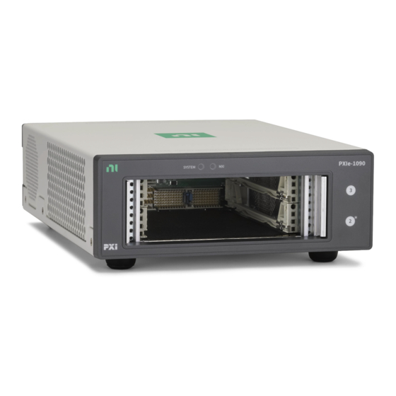
Page 3: Chassis Components
0 °C to 50 °C temperature range • Power supply, temperature, and fan monitoring Chassis Components The following figures show key features of the PXIe-1090 chassis front and back panels. Figure 1. PXIe-1090 Front Panel Features 1. System LED 4. PXI Express Hybrid Peripheral Slot 2. -
Page 4: Pxie-1090 Backplane Overview
The PXIe-1090 chassis has a built-in Intel Thunderbolt 3 interface accessible through two Thunderbolt 3 ports on the back of the chassis. This enables control of the PXIe-1090 from a host PC that includes a Thunderbolt 3 port and is running a native (nonvirtualized) operating system that supports Thunderbolt connectivity. -
Page 5: Basic Mxi-Express Thunderbolt Systems
Figure 3. Example of a Basic MXI-Express Thunderbolt Link Topology Thunderbolt Bus Extension You can daisy-chain from a PXIe-1090 controlled by a PC to an additional Thunderbolt 3 compatible device. The following figure shows how you can use a PXIe-1090 to connect multiple Thunderbolt 3 compatible devices to a PC in a daisy-chain topology. -
Page 6: Hybrid Peripheral Slot
The backplane routes PXI Local Bus 6 between PXI slots. The left local bus 6 from slot 2 and right local bus 6 from slot 3 are not routed anywhere. Local bus signals may range from high-speed TTL signals to analog signals as high as 42 V. 6 | ni.com | PXIe-1090 User Guide... -
Page 7: Pxi Trigger Bus
Modules can pass triggers to one another on the lines, allowing precisely timed responses to asynchronous external events the system is monitoring or controlling. Dynamic routing of triggers (automatic line assignments) is supported through certain NI drivers like NI-DAQmx. -
Page 8: Installation And Configuration
Unsuitable modifications may result in safety hazards. Chassis Cooling Considerations The PXIe-1090 chassis is designed to operate on a bench or in an instrument rack. You must adhere to the cooling clearances as outlined in the following section. 8 | ni.com | PXIe-1090 User Guide... - Page 9 Providing Adequate Clearance As shown below, the PXIe-1090 module and power supply intake vents are on the right side of the chassis. The module and power supply exhaust vents are on the left side of the chassis. Figure 6. PXIe-1090 Cooling Air Flow 1.
- Page 10 To aid in thermal health monitoring for either rack or benchtop use, you can monitor the chassis intake temperatures in Measurement & Automation Explorer (MAX) to ensure the temperatures do not exceed the ratings in the Operating Environment section of the PXIe-1090 Specifications.
-
Page 11: Connecting The Safety Ground
0.8 m 787580-0R8 Connect the MXI-Express Thunderbolt cable to the host PC Thunderbolt port and PXIe-1090. The cables have no polarity, so you can connect either end to either Thunderbolt port. The PXIe-1090 User Guide | © National Instruments Corporation | 11... -
Page 12: Powering On/Off The Mxi-Express Thunderbolt System
To power off the PXIe-1090 AC off Observe the PXIe-1090 LED status where applicable. A properly connected and powered up system should report a valid link and power status once the host PC is powered on. Refer to LED Indicators for more information. -
Page 13: Installing Peripheral Modules
To avoid possible damage to a peripheral module when you install it in the PXIe-1090 chassis, the chassis must be in a vertical orientation, as shown in the following figure. Do not install a peripheral module with the chassis in a horizontal orientation. -
Page 14: Led Indicators
3. Peripheral Module Front Panel Mounting Screws (2x) LED Indicators MXI LED The tri-color MXI LED on the PXIe-1090 front panel gives status information about the power supply and link state, as the following table describes. Table 5. MXI LED Colors Color Meaning Power is off. -
Page 15: Dip Switches
Indicates temperature is out of range, or an internal chassis fault has Steady red occurred. DIP Switches Use the DIP switches to control chassis behavior. Refer to the following figure for the DIP switches location. Figure 10. PXIe-1090 Dip Switches Location PXIe-1090 User Guide | © National Instruments Corporation | 15... -
Page 16: Inhibit Mode
Set host power up mode to Manual. Inhibit Mode The PXIe-1090 chassis supports operation in two inhibit modes. Use Default mode when you desire normal Power Inhibit switch functionality. In Default mode, when no host is connected 16 | ni.com | PXIe-1090 User Guide... -
Page 17: Default Host Power Up Mode
AC power. Inhibit Mode Selection You can select the PXIe-1090 chassis Inhibit Mode using a DIP switch on the top of the card cage. Refer to the DIP Switches section for the DIP switch location and more information about DIP switch settings. -
Page 18: Pxi Express System Configuration With Max
You also can select the PXIe-1090 chassis fan mode using a DIP switch. Refer to the DIP Switches section for more information. Note The DIP switch must be in the Auto position for software configuration in MAX to work. If the DIP switch is in the High position, the chassis fan mode will be High regardless of the software setting. - Page 19 DAQmx, avoids double-driving and potentially damaging trigger lines. The PXIe-1090 has a trigger bus with eight lines numbered 0 through 7 that can be reserved and routed statically or dynamically. Static reservation pre-allocates a trigger line to prevent its configuration by a user program.
-
Page 20: Using System Configuration And Initialization Files
You can configure fan behavior using software settings in MAX. The PXIe-1090 supports both Auto and High fan modes for both the 38 W and 58 W cooling profiles. Refer to the Fan Mode section for more information about these modes. - Page 21 Maintenance This section describes basic maintenance procedures you can perform on the PXIe-1090 chassis. Caution Disconnect the power cable prior to servicing your PXIe-1090 chassis. Service Interval Clean dust from the chassis exterior (and interior) as needed, based on the operating environment.
- Page 22 . You can find patents.txt ni.com/patents information about end-user license agreements (EULAs) and third-party legal notices in the readme file for your NI product. Refer to the Export Compliance Information at for the NI global trade compliance policy and how ni.com/legal/export-compliance...
Need help?
Do you have a question about the PXIe-1090 and is the answer not in the manual?
Questions and answers