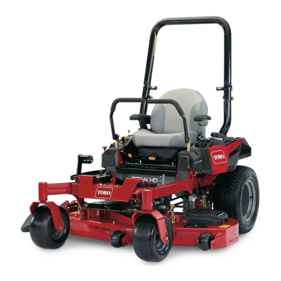
Toro TITAN HD 1500 Series Operator's Manual
48in, 52in, or 60in riding mower
Hide thumbs
Also See for TITAN HD 1500 Series:
- Operator's manual (88 pages) ,
- Operator's manual (68 pages) ,
- Operator's manual (92 pages)
Table of Contents
Advertisement
Register at www.Toro.com.
Original Instructions (EN)
48in, 52in, or 60in TITAN
1500, 2000, or 2500 Series Riding
Mower
Model No. 74450—Serial No. 402100000 and Up
Model No. 74451—Serial No. 402100000 and Up
Model No. 74452—Serial No. 402100000 and Up
Model No. 74463—Serial No. 402100000 and Up
Model No. 74465—Serial No. 400000000 and Up
Model No. 74466—Serial No. 400000000 and Up
Model No. 74467—Serial No. 400000000 and Up
Model No. 74470—Serial No. 402100000 and Up
Model No. 74471—Serial No. 402100000 and Up
Model No. 74472—Serial No. 402100000 and Up
Model No. 78450—Serial No. 402100000 and Up
Model No. 78472—Serial No. 400000000 and Up
Form No. 3421-127 Rev B
®
HD
*3421-127* B
Advertisement
Table of Contents

Related Manuals for Toro TITAN HD 1500 Series


Summary of Contents for Toro TITAN HD 1500 Series
- Page 1 Model No. 74470—Serial No. 402100000 and Up Model No. 74471—Serial No. 402100000 and Up Model No. 74472—Serial No. 402100000 and Up Model No. 78450—Serial No. 402100000 and Up Model No. 78472—Serial No. 400000000 and Up *3421-127* B Register at www.Toro.com. Original Instructions (EN)
- Page 2 Use of this product may cause exposure Important: If you are using a machine with a Toro to chemicals known to the State of engine above 1500 m (5,000 ft) for a continuous California to cause cancer, birth defects, period, ensure that the High Altitude Kit has been or other reproductive harm.
-
Page 3: Table Of Contents
Servicing a Kawasaki ® Engine ......42 Important calls attention to special mechanical Servicing a Kohler ® Engine....... 47 information and Note emphasizes general information Servicing a Toro Engine ........52 worthy of special attention. Checking the Spark Arrester ......57... -
Page 4: Safety
Safety Replacing the Emissions-Air Intake Filter.............. 58 Fuel System Maintenance ........58 This machine has been designed in accordance with Replacing the Fuel Filter ........58 ANSI B71.4-2012. Servicing the Fuel Tank........59 Electrical System Maintenance ......59 Electrical System Safety ........59 General Safety Servicing the Battery......... -
Page 5: Slope Indicator
Slope Indicator g011841 Figure 5 You may copy this page for personal use. 1. The maximum slope you can operate the machine on is 15 degrees. Use the slope chart to determine the degree of slope of hills before operating. Do not operate this machine on a slope greater than 15 degrees. Fold along the appropriate line to match the recommended slope. -
Page 6: Safety And Instructional Decals
Safety and Instructional Decals Safety decals and instructions are easily visible to the operator and are located near any area of potential danger. Replace any decal that is damaged or missing. decaloemmarkt Manufacturer's Mark decal106-5517 1. Indicates the blade is identified as a part from the original 106-5517 machine manufacturer. - Page 7 decal109-6014 decal112-3858 109-6014 112-3858 1500 and 2000 Series Side Discharge Machines Only 1. Read the Operator's 3. Remove the key before Manual. adjusting the height of cut. 2. Read the instructions 4. Height-of-cut settings. before servicing or performing maintenance. decal112-9028 112-9028 decal109-6035 109-6035...
- Page 8 decal116-5610 116-5610 1. Hour meter 4. Neutral 2. Power takeoff (PTO) 5. Operator-presence switch decal117-1194 117-1194 3. Parking brake 6. Battery 1500 and 2000 Series Side-Discharge Machines Only 1. Engine decal117-2718 117-2718 decal116-8588 116-8588 1. Read the Operator’s Manual. 2. Rotate the drive release knob to loosen, slide the knob, and tighten.
- Page 9 decal126-0768 126-0768 Rear Discharge Units Only decal126-4784 126-4784 1. Height of cut decal126-4363 126-4363 1. Cutting/dismemberment hazard, fan and entanglement hazard, belt. Shut off the engine and remove the key before adjusting, servicing or cleaning the machine. decal126-6599 126-6599 Rear Discharge Units 1.
- Page 10 2. Fill to the bottom of the Manual. filler neck; warning—do not overfill the tank. decal131-1097 131-1097 Toro Engines Only 1. Oil drain decal127-0326 127-0326 2500 Series Side Discharge Machines Only 3. Remove the key and 1. Read the Operator's Manual.
- Page 11 decalptosymbols PTO Switch Symbols 1. PTO–disengage 2. PTO–engage decaltransportlock decal136-8992 Transport Lock 136-8992 1. Height of cut 2. Pull up to unlock the Machines with MyRide Only transport lock. 1. Fuel—full 3. Fuel—empty 2. Fuel—50% decal136-9024 136-9024 1. Read the Operator’s 4.
- Page 12 decalmotioncntrlrh-126-6183 Right Motion Control 1. Machine speed 4. Neutral 2. Fast 5. Reverse 3. Slow decal126-8151 126-8151 1. Read the instructions before servicing or performing 4. Refer to the Operator's Manual for grease instructions. maintenance on the machine. 2. Time interval 5.
- Page 13 decal126-8383 126-8383 Machines without MyRide Only Note: This machine complies with the industry standard stability test in the static lateral and longitudinal tests with the maximum recommended slope indicated on the decal. Review the instructions for operating the machine on slopes in the Operator’s Manual as well as the conditions in which you would operate the machine to determine whether you can operate the machine in those conditions on that day and at that site.
- Page 14 decal132-0871 132-0871 Machines with MyRide Only Note: This machine complies with the industry standard stability test in the static lateral and longitudinal tests with the maximum recommended slope indicated on the decal. Review the instructions for operating the machine on slopes in the Operator’s Manual as well as the conditions in which you would operate the machine to determine whether you can operate the machine in those conditions on that day and at that site.
-
Page 15: Product Overview
Key Switch Product Overview The key switch, used to start and shut off the engine, has 3 positions: O , and S . Refer to TART Starting the Engine (page 28). Choke Control Use the choke control to start a cold engine. Throttle Control The throttle controls the engine speed, and it has a continuous-variable setting from the S... - Page 16 Contact your Authorized Service Dealer or authorized Toro distributor or go to www.Toro.com for a list of all approved attachments and accessories. To ensure optimum performance and continued safety certification of the machine, use only genuine Toro replacement parts and accessories.
-
Page 17: Specifications
Specifications Note: Specifications and design are subject to change without notice. Width—Machines with Side Discharge Mower Decks 48-inch Deck 52-inch Deck 60-inch Deck Without mower deck 121 cm (47-1/2 inches) 124 cm (49 inches) 133 cm (52 inches) Deflector up 133 cm (53 inches) 144 cm (56-3/4 inches) 161 cm (63-1/2 inches) -
Page 18: Before Operation
Operation containers on the ground, away from your vehicle before filling. • Remove the equipment from the truck or trailer Note: Determine the left and right sides of the and refuel it while it is on the ground. If this is not machine from the normal operating position. - Page 19 Filling the Fuel Tank MTBE are not the same. Gasoline with 15% ethanol (E15) by volume is not approved for use. Park the machine on a level surface. Never use gasoline that contains more than 10% ethanol by volume, such as E15 (contains Engage the parking brake.
-
Page 20: Performing Daily Maintenance
Using the Rollover-Protection System (ROPS) WARNING To avoid injury or death from rollover, keep the roll bar in the fully raised, locked position and use the seat belt. Ensure that the seat is secured to the machine. WARNING There is no rollover protection when the roll bar is in the down position. -
Page 21: Using The Safety-Interlock System
Using the Safety-Interlock System WARNING If the safety-interlock switches are disconnected or damaged, the machine could operate unexpectedly, causing personal injury. • Do not tamper with the interlock switches. • Check the operation of the interlock switches daily and replace any damaged switches before operating the machine. -
Page 22: Positioning The Seat
Testing the Safety-Interlock Positioning the Seat System The seat can move forward and backward (Figure 13). Position the seat where you have the best control of Service Interval: Before each use or daily the machine and are most comfortable. Test the safety-interlock system before you use the machine each time. -
Page 23: Adjusting The Myride™ Suspension System
Adjusting the MyRide™ Adjust the rear-shock assemblies (Figure 16). Suspension System The MyRide™ suspension system adjusts to provide a smooth and comfortable ride. You can adjust the rear 2-shock assemblies to quickly and easily change the suspension system. Position the suspension system where you are most comfortable. -
Page 24: Using Attachments And Accessories
• Ensure that all drives are in neutral, the parking brake is engaged, and you are in the operating Use only Toro approved attachments and accessories. position before you start the engine. If more than one accessory-mount kit (i.e., bucket •... - Page 25 hearing loss through extended periods of the machine and any hazard. Use a walk-behind exposure. machine or a hand trimmer to mow the grass in these areas. • Avoid starting, stopping, or turning the machine on slopes. Avoid making sudden changes in speed or direction;...
-
Page 26: Entering The Operator's Position
Entering the Operator’s Disengaging the Parking Brake Position Use the mower deck as a step to get into the operator’s position (Figure 20). g192635 g029797 Figure 22 Figure 20 Operating the Mower Operating the Parking Blade-Control Switch (PTO) Brake The blade-control switch (PTO) starts and stops the Always engage the parking brake when you stop the mower blades and any powered attachments. -
Page 27: Operating The Throttle
Disengaging the Blade-Control Operating the Choke Switch (PTO) Use the choke to start a cold engine. Pull up the choke knob to engage the choke before using the key switch (Figure 26). Push down the choke knob to disengage the choke after the engine has started (Figure 26). -
Page 28: Starting The Engine
Starting the Engine Shutting Off the Engine Note: Note: A warm or hot engine may not require choking. Refer to Figure 46 to determine which engine you have. Important: Do not engage the starter for more than 5 seconds at a time. Engaging the starter CAUTION motor for more than 5 seconds can damage the starter motor. - Page 29 Shutting Off Kohler Engines Shutting Off Toro Engines Note: Let the engine idle at mid-throttle for 60 seconds Ensure the throttle is in the F position before turning the switch off. before shutting off the engine. g037049 g231028 Figure 30...
-
Page 30: Using The Motion-Control Levers
Using the Motion-Control WARNING Levers The machine can spin very rapidly. You may lose control of the machine and cause personal injury or damage to the machine. • Use caution when making turns. • Slow the machine down before making sharp turns. -
Page 31: Adjusting The Height Of Cut
Driving Backward Adjusting the Height of Cut Move the levers to the center, unlocked position. Using the Transport Lock To go backward, slowly pull the motion-control levers rearward (Figure 33). The transport lock has 2 positions, and is used with the deck-lift pedal. -
Page 32: Adjusting The Anti-Scalp Rollers
Adjusting the Height-of-Cut Pin Adjust the anti-scalp rollers as shown in Figure Figure Adjust the height-of-cut from 38 to 127 mm (1-1/2 to 5 inches) in 6 mm (1/4 inch) increments by moving the height-of-cut pin into different hole locations. Move the transport lock to the L position. -
Page 33: Adjusting The Side Bumpers
Adjusting the Side Bumpers Using the Side Discharge The mower has a hinged grass deflector that Rear-Discharge Machines Only disperses clippings to the side and down toward the turf. Install the side bumpers in the top holes when operating in a height of cut higher than 64 mm (2-1/2 DANGER inches) and in the center holes when operating in a height of cut lower than 64 mm (2-1/2 inches). -
Page 34: After Operation
File down any nicks and Figure 39 sharpen the blades as necessary. If a blade is 1. O position 2. O position damaged or worn, replace it immediately with a genuine Toro replacement blade. -
Page 35: Using The Drive-Wheel Release Valves
Using the Drive-Wheel Release Valves WARNING Hands may become entangled in the rotating drive components below the engine deck, which could result in serious injury. Shut off the engine, remove the key, and allow all moving parts to stop before accessing the drive-wheel release valves. -
Page 36: Transporting The Machine
Transporting the Machine Use a heavy-duty trailer or truck to transport the machine. Use a full-width ramp. Ensure that the trailer or truck has all the necessary brakes, lighting, and marking as required by law. Please carefully read all the safety instructions. Knowing this information could help you or bystanders avoid injury. - Page 37 If using a trailer, connect it to the towing vehicle and connect the safety chains. If applicable, connect the trailer brakes and lights. Lower the ramp, ensuring that the angle between the ramp and the ground does not exceed 15 degrees (Figure 41).
-
Page 38: Maintenance
• For Toro engines with a standard air cleaner—service the air-cleaner paper element (more often in dusty, dirty conditions). • For Toro engines—change the engine oil and oil filter (more often in dusty, dirty conditions). • For Toro engines—check the spark plug(s). -
Page 39: Pre-Maintenance Procedures
• For Kawasaki engines—check the safety air filter (more often in dusty or sandy conditions). Every 250 hours • For Toro engines with a heavy-duty air cleaner—replace the air filter (more often in dusty or sandy conditions). • After the initial change—change the hydraulic-system filters and fluid when using Mobil 1 15W50 fluid (change it more often under severe conditions). -
Page 40: Lubrication
Lubrication by a safety device. Check their proper operation regularly. • Check the parking brake operation frequently. Greasing the Machine Adjust and service as required. Service Interval: Every 25 hours—Grease the front caster axles. (more often in dirty or dusty conditions). Every 50 hours—Grease the pump-idler pivot. -
Page 41: Lubricating The Caster-Wheel Hubs
Lubricating the approximately 3 mm (1/8 inch) from the outer surface of the spacer nut to the end of the axle Caster-Wheel Hubs inside the nut. Insert the assembled nut and axle into the wheel 2500 Series Machines Only on the side with the new seal and bearing. Service Interval: Yearly—For 2500 Series With the open end of the wheel facing up, fill machines—Lubricate the... -
Page 42: Engine Maintenance
Use the following graphic to identify the engine you have and proceed to the section listed below for service (Figure 46). g231391 Figure 46 1. Kawasaki engine 3. Toro engine with standard air cleaner 2. Kohler engine 4. Toro engine with heavy-duty air cleaner • For Kawasaki engine maintenance, refer to Servicing a Kawasaki ®... - Page 43 Servicing the Air Cleaner Important: Do not attempt to clean the safety filter. If the safety filter is dirty, then Service Interval: Every 250 hours—For Kawasaki the primary filter is damaged. Replace both engines—replace the primary air filters. filter (more often in dusty or sandy Inspect the primary filter for damage by looking conditions).
- Page 44 Servicing the Engine Oil Engine-Oil Specifications Oil Type: Detergent oil (API service SF, SG, SH, SJ, or SL) Crankcase Capacity: 1.8 L (61 fl oz) without the oil filter; 2.1 L (71 fl oz) with the oil filter g036856 Viscosity: See the table below. g037096 Figure 49 Note:...
- Page 45 Disengage the blade-control switch (PTO) and Slowly pour approximately 80% of the specified engage the parking brake. oil into the filler tube and slowly add the additional oil to bring it to the Full mark (Figure Shut off the engine, remove the key, and wait 52).
- Page 46 Servicing the Spark Plug Changing the Engine-Oil Filter Service Interval: Every 200 hours—For Kawasaki Service Interval: Every 100 hours engines—change the engine-oil Ensure that the air gap between the center and side filter (more often in dirty or dusty electrodes is correct before installing the spark plug. conditions).
-
Page 47: Servicing A Kohler Engine
Servicing a Kohler ® Engine Checking the Spark Plug Important: Do not clean the spark plug(s). This section is only for machines with Kohler engines. Always replace the spark plug(s) when it has a If your engine looks like the one shown in Figure black coating, worn electrodes, an oily film, or you have a Kohler engine. - Page 48 Removing the Elements Servicing the Paper Element Gently tap the paper element to dislodge dirt. Rotate the latches outward. Note: Do not wash the paper element or use Remove the cover to access the air-cleaner pressurized air, as this will damage the element. elements (Figure 58).
-
Page 49: Disengage The Blade-Control Switch (Pto) And Engage The Parking Brake
Changing the Engine Oil and the Engine-Oil Shut off the engine, remove the key, and wait for all moving parts to stop before leaving the Filter operating position. Service Interval: Every 100 hours—For Kohler Note: Ensure that the engine is cool so that the engines—change the engine oil and oil has had time to drain into the sump. - Page 50 g027517 Figure 64 Dispose the used oil at a recycling center. g028127 Figure 63 Slowly pour approximately 80% of the specified oil into the filler tube and slowly add the additional oil to bring it to the Full mark (Figure 64).
- Page 51 Servicing the Spark Plug Service Interval: Every 200 hours—For Kohler engines—check the spark plug(s). Every 500 hours—For Kohler engines—replace the spark plug(s). The spark plug is RFI compliant; you can also use an equivalent plug. g206628 Figure 66 Type: Champion XC12YC Air Gap: 0.76 mm (0.03 inch) Installing the Spark Plug Removing the Spark Plug...
-
Page 52: Servicing A Toro Engine
Servicing a Toro Engine This section is only for machines with Toro engines. If your engine looks like 1 of the 2 engines shown in Figure 68, you have a Toro engine. g027800 g231404 Figure 68 1. Standard air cleaner 2. - Page 53 Gently tap the paper element to dislodge dirt. Engines with a Heavy-Duty Air Cleaner Note: Do not wash the paper element or use Service Interval: Every 250 hours—For Toro pressurized air, as this will damage the element. engines with a heavy-duty air cleaner—replace the air filter (more...
- Page 54 Figure 73 g029368 Figure 74 Checking the Engine-Oil Level Service Interval: Before each use or daily—For Toro engines—check the engine-oil level. Changing the Engine Oil and Oil Filter Note: Check the oil when the engine is cold. Service Interval: After the first 5 hours/After the first...
-
Page 55: Drain The Oil From The Engine
oil and oil filter (more often in dusty, dirty conditions). Note: Dispose of the used oil at a recycling center. Park the machine on a level surface to ensure that the oil drains completely. Disengage the blade-control switch (PTO) and engage the parking brake. -
Page 56: Oil Into The Filler Tube And Slowly Add The Additional Oil To Bring It To The Full Mark
Figure 76 Every 200 hours/Every 2 years (whichever comes first)—For Toro engines—replace the spark plug(s). Slowly pour approximately 80% of the specified Ensure that the air gap between the center and side oil into the filler tube and slowly add the electrodes is correct before installing the spark plug. -
Page 57: Checking The Spark Arrester
Cleaning the Cooling System Park the machine on a level surface, disengage the blade-control switch (PTO), and engage the parking brake. Shut off the engine, remove the key, and wait for all moving parts to stop before leaving the operating position. g027478 Remove the air filter from the engine. -
Page 58: Replacing The Emissions-Air Intake Filter
Replacing the Fuel System Emissions-Air Intake Filter Maintenance Service Interval: Every 500 hours DANGER Park the machine on a level surface, disengage In certain conditions, fuel is extremely the blade-control switch (PTO), and engage the parking brake. flammable and highly explosive. A fire or explosion from fuel can burn you, others, and Shut off the engine, remove the key, and wait can damage property. -
Page 59: Servicing The Fuel Tank
Electrical System Maintenance Electrical System Safety • Disconnect the battery before repairing the machine. Disconnect the negative terminal first and the positive last. Connect the positive terminal first and the negative last. • Charge the battery in an open, well-ventilated area, away from sparks and flames. - Page 60 Charging the Battery WARNING Incorrectly removing the cables from WARNING battery could damage the machine and Charging the battery produces gasses that cables, causing sparks. Sparks can can explode. cause the battery gasses to explode, resulting in personal injury. Never smoke near the battery and keep sparks •...
-
Page 61: Servicing The Fuses
Installing the Battery Servicing the Fuses Position the battery in the tray with the terminal The electrical system is protected by fuses. It requires posts opposite from the hydraulic tank (Figure no maintenance; however, if a fuse blows check the 82). -
Page 62: Drive System Maintenance
Drive System Maintenance Checking the Seat Belt Service Interval: Before each use or daily Inspect the seat belt for wear, cuts, and proper operation of the retractor and buckle. Replace the seat belt if it is damaged. Checking the Roll-Bar Knobs Service Interval: Before each use or daily WARNING... -
Page 63: Adjusting The Tracking
Adjusting the Tracking Checking the Tire Pressure Disengage the blade-control switch (PTO). Service Interval: Every 50 hours/Monthly (whichever comes first) Drive to an open, flat area and move the motion-control levers to the N EUTRAL LOCK Maintain the air pressure in the front and rear tires position. -
Page 64: Cooling System Maintenance
Brake Maintenance Cooling System Maintenance Adjusting the Parking Brake Cleaning the Engine Screen Service Interval: Every 500 hours Service Interval: Before each use or daily Note: Perform this procedure whenever you remove Before each use or daily or replace a brake component. Before each use remove any buildup of grass, dirt, or Park the machine on a level surface, disengage other debris from the engine screen, engine exhaust,... - Page 65 Rotate the brake-linkage shaft until the end aligns with the hole in the lever. • Shorten the linkage by turning it clockwise. • Lengthen the linkage by turning it counterclockwise. Insert the brake-linkage shaft into the parking-brake hole and secure with the cotter pin.
-
Page 66: Belt Maintenance
Remove the spring tension from the spring-loaded idler pulley. Refer to Figure 94 Figure Note: For 1500 and 2000 Series mower decks, use the spring removal tool (Toro Part No. 92-5771) to remove the spring from the mower-deck post (Figure 94). g028279... -
Page 67: Replacing The Mower Belt For Rear-Discharge Mower Decks
Replacing the Mower Belt for Rear-Discharge Mower Decks Replacing the Counter-Rotating Belt Park the machine on a level surface, disengage the blade-control switch (PTO), and engage the parking brake. Shut off the engine, remove the key, and wait for all moving parts to stop before leaving the operating position. - Page 68 Remove the belt from the remaining pulleys (Figure 97). Route the new belt abound the mower pulleys. Using the ratchet in the square hole, remove the tension on the spring, and guide the new belt around the idler pulley (Figure 97).
-
Page 69: Replacing The Hydraulic Pump-Drive Belt
Replacing the Hydraulic Pump-Drive Belt Park the machine on a level surface, disengage the blade-control switch (PTO), and engage the parking brake. Shut off the engine, remove the key, and wait for all moving parts to stop before leaving the operating position. -
Page 70: Controls System Maintenance
Adjusting the Tilt Controls System Disengage the blade-control switch (PTO), move Maintenance the motion-control levers to the N EUTRAL LOCK position, and engage the parking brake. Adjusting the Shut off the engine, remove the key, and wait for all moving parts to stop before leaving the Control-Handle Position operating position. -
Page 71: Adjusting The Motion-Control Linkage
Adjusting the Adjust the pump-control-rod lengths by turning the nut in the appropriate direction until the Motion-Control Linkage wheels slightly creep in reverse (see Figure 105). Located on either side of the machine, below the seat, Move the motion-control levers to the R EVERSE are the pump-control linkages. -
Page 72: Hydraulic System Maintenance
Service Interval: After the first 75 hours—Change the System hydraulic-system filters and fluid. Every 500 hours—After the initial change—change the hydraulic-system Hydraulic Fluid Specifications filters and fluid when using Toro ® HYPR-OIL ™ 500 fluid (change it more often under severe Hydraulic Fluid Type: Toro ®... - Page 73 Locate the filter and guards on each Slowly pour the specified fluid through the transaxle-drive system (Figure 107). expansion reservoir until fluid comes out of 1 of the vent-plug holes. Remove the 3 screws securing the filter guard and guard (Figure 107).
-
Page 74: Mower Deck Maintenance
Bleeding the Hydraulic System Mower Deck Raise the rear of machine and support it with Maintenance jack stands (or equivalent support) just high enough to allow the drive wheels to turn freely. Servicing the Cutting Blades To ensure a superior quality of cut, keep the blades sharp. - Page 75 g006530 Figure 110 1. Cutting edge 3. Wear/slot forming g014973 Figure 112 2. Curved area 4. Crack 1. Blade (in position for measuring) 2. Level surface Checking for Bent Blades 3. Measured distance between blade and the surface (A) Note: The machine must be on a level surface for Rotate the same blade 180 degrees so that the following procedure.
- Page 76 g014973 Figure 114 1. Opposite blade edge (in position for measuring) 2. Level surface 3. Second measured distance between blade and surface (B) g017443 If the difference between A and B is greater Figure 115 than 3 mm (1/8 inch), replace the blade with a new blade;...
- Page 77 Remove the right blade bolt (left-hand threaded bolt), curved washer, and blade from the spindle shaft (Figure 117). Note: Note the blade type and where each blade is installed. See Figure 117 for the correct position. g024248 Figure 117 g017443 1.
-
Page 78: Leveling The Mower Deck
Note: If the blade is not balanced, file some metal off the end of the sail area only (Figure 118). g000553 Figure 119 1. Blade 2. Balancer g229303 Repeat this procedure until the blade is balanced. Leveling the Mower Deck Check to ensure that the mower deck is level any time you install the mower or when you see an uneven cut on your lawn. - Page 79 Set the anti-scalp rollers to top holes or remove them completely for this adjustment. Place 2 blocks (see table below) under the rear edge of the cutting deck skirt; 1 on each side of the cutting deck (Figure 122). Set the height-of-cut lever to the 3 inch (76 mm) position.
-
Page 80: Removing The Mower Deck
Removing the Mower Deck Park the machine on a level surface, disengage the blade-control switch (PTO), and engage the parking brake. Shut off the engine, remove the key, and wait for all moving parts to stop before leaving the operating position. Lower the height-of-cut lever to the lowest position. -
Page 81: Cleaning
Cleaning Cleaning under the Mower Deck Service Interval: Before each use or daily Park the machine on a level surface, disengage the blade-control switch (PTO), and engage the parking brake. Shut off the engine, remove the key, and wait for all moving parts to stop before leaving the g015594 operating position. -
Page 82: Storage
Storage Check the condition of the blades; refer to Servicing the Cutting Blades (page 74). Prepare the machine for storage when non-use Storage Safety occurs over 30 days. Prepare the machine for storage as follows: • Shut off the engine, remove the key, wait for all moving parts to stop, and allow the machine to Add a petroleum-based cool before storing it. -
Page 83: Troubleshooting
Troubleshooting Problem Possible Cause Corrective Action The engine overheats. 1. The engine load is excessive. 1. Reduce the ground speed. 2. The oil level in the crankcase is low. 2. Add oil to the crankcase. 3. The cooling fins and air passages 3. - Page 84 Problem Possible Cause Corrective Action The machine does not drive. 1. The bypass valves are not closed tight. 1. Tighten the bypass valves. 2. The pump belt is worn, loose, or 2. Change the belt. broken. 3. The pump belt is off a pulley. 3.
-
Page 85: Schematics
Schematics g018479 Wire Diagram—Toro Engines (Rev. A) - Page 86 g036151 Wire Diagram—Kohler Engines (Rev. A)
- Page 87 g037072 Wire Diagram—Kawasaki Engines (Rev. A)