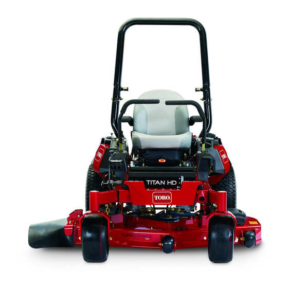
Toro TITAN HD 1500 Operator's Manual
48 in, 52 in, or 60 in riding mower
Hide thumbs
Also See for TITAN HD 1500:
- Operator's manual (88 pages) ,
- Operator's manual (92 pages) ,
- Operator's manual (68 pages)
Table of Contents
Advertisement
Register at www.Toro.com.
Original Instructions (EN)
48in, 52in, or 60in TITAN
1500, 2000, or 2500 Series Riding
Mower
Model No. 74450—Serial No. 400010798 and Up
Model No. 74451—Serial No. 400010798 and Up
Model No. 74452—Serial No. 400010798 and Up
Model No. 74460—Serial No. 400010798 and Up
Model No. 74461—Serial No. 400010798 and Up
Model No. 74462—Serial No. 400010798 and Up
Model No. 74463—Serial No. 400010798 and Up
Model No. 74470—Serial No. 400010798 and Up
Model No. 74471—Serial No. 400010798 and Up
Model No. 74472—Serial No. 400010798 and Up
Model No. 78450—Serial No. 400010798 and Up
Form No. 3405-604 Rev D
®
HD
*3405-604* D
Advertisement
Table of Contents

Related Manuals for Toro TITAN HD 1500


Summary of Contents for Toro TITAN HD 1500
- Page 1 Model No. 74463—Serial No. 400010798 and Up Model No. 74470—Serial No. 400010798 and Up Model No. 74471—Serial No. 400010798 and Up Model No. 74472—Serial No. 400010798 and Up Model No. 78450—Serial No. 400010798 and Up *3405-604* D Register at www.Toro.com. Original Instructions (EN)
-
Page 2: Figure
Replace all parts including, but not limited to, tires, belts, blades, and fuel system components with original Toro parts. For all models that do not have Toro engines, please refer to the engine manufacturer’s information included with the machine. Labeled power ratings are supplied by the engine... -
Page 3: Table Of Contents
Whenever you need service, genuine Toro parts, or Slope Indicator ........... 6 additional information, contact an Authorized Service Safety and Instructional Decals ......7 Dealer or Toro Customer Service and have the model Product Overview ........... 14 and serial numbers of your product ready. Figure 1 Controls ............ - Page 4 Servicing a Kawasaki ® Engine ......41 Servicing a Kohler ® Engine....... 46 Servicing a Toro Engine ........50 Checking the Spark Arrester ......55 Replacing the Emissions-Air Intake Filter.............. 55 Fuel System Maintenance ........55 Replacing the Fuel Filter ........55 Servicing the Fuel Tank........
-
Page 5: Safety
Safety This machine has been designed in accordance with ANSI B71.4-2012. General Safety This product is capable of amputating hands and feet and of throwing objects. Always follow all safety instructions to avoid serious personal injury. Using this product for purposes other than its intended use could prove dangerous to you and bystanders. -
Page 6: Slope Indicator
Slope Indicator g011841 Figure 4 This page may be copied for personal use. 1. The maximum slope you can safely operate the machine on is 15 degrees. Use the slope chart to determine the degree of slope of hills before operating. Do not operate this machine on a slope greater than 15 degrees. Fold along the appropriate line to match the recommended slope. -
Page 7: Safety And Instructional Decals
Safety and Instructional Decals Safety decals and instructions are easily visible to the operator and are located near any area of potential danger. Replace any decal that is damaged or missing. decaloemmarkt Manufacturer's Mark 1. Indicates the blade is identified as a part from the original machine manufacturer. - Page 8 decal112-9028 112-9028 1. Warning—stay away from moving parts; keep all guards in place. decal109-6035 109-6035 2500 Series Side Discharge Machines Only decal115-9625 115-9625 1. Parking 2. Parking brake—engaged brake—disengaged decal109-6036 109-6036 Rear Discharge Machines Only 1. Read the Operator’s Manual. 2.
- Page 9 decal117-3848 117-3848 1. Thrown object hazard—keep bystanders a safe distance from the machine. 2. Thrown object hazard, mower—do not operate the machine without deflector, discharge cover, or grass collection system in place. decal116-8588 116-8588 3. Cutting/dismemberment of hand or foot—stay away from moving parts;...
- Page 10 decal126-8161 126-8161 1. Read the Operator’s 3. Press down on latch to unlock seat Manual. 4. Rotate seat 2. Slide seat forward decal126-9939 126-9939 decal126-4784 126-4784 1. Read the Operator’s 2. Fill to bottom of filler neck; Manual warning–do not overfill the 1.
- Page 11 131-1097 Toro Engines Only decal127-6662 1. Oil drain 127-6662 Rear Discharge Mowers Only 1. Attention—read the 3. Remove the bolt by turning Operator's Manual. it counter clockwise. 2. Remove the nut by turning it clockwise. decal136-1305 136-1305 1. Fast 4.
- Page 12 decalptosymbols PTO Switch Symbols 1. PTO–disengage 2. PTO–engage decalmotioncntrlrh-126-6183 Right Motion Control 1. Machine speed 4. Neutral decaltransportlock 2. Fast 5. Reverse Transport Lock 3. Slow 1. Height of cut 2. Pull up to unlock the transport lock decalbatterysymbols Battery Symbols Some or all of these symbols are on your battery.
- Page 13 decal126-8151 126-8151 1. Read the instructions before servicing or performing 4. Refer to the Operator's Manual for grease instructions maintenance 2. Time interval 5. Check the hydraulic-fluid level and refer to the Operator's Manual or further instructions 3. Check oil level 6.
-
Page 14: Product Overview
A selection of Toro approved attachments and accessories is available for use with the machine to enhance and expand its capabilities. Contact your Authorized Service Dealer or Distributor or go to www.Toro.com for a list of all approved attachments and accessories. -
Page 15: Specifications
Specifications Note: Specifications and design are subject to change without notice. Width—Machines with Side Discharge Mower Decks 48-inch Deck 52-inch Deck 60-inch Deck Without mower deck 121 cm (47-1/2 inches) 124 cm (49 inches) 133 cm (52 inches) Deflector up 133 cm (53 inches) 144 cm (56-3/4 inches) 161 cm (63-1/2 inches) -
Page 16: Before Operation
Operation • Do not fill containers inside a vehicle or on a truck or trailer bed with a plastic liner. Always place containers on the ground, away from your vehicle Note: Determine the left and right sides of the before filling. machine from the normal operating position. -
Page 17: Recommended Fuel
41), for Kohler engines refer to Servicing chance of varnish deposits in the fuel system, use a Kohler ® Engine (page 46), and for Toro engines fuel stabilizer at all times. refer to Servicing a Toro Engine (page 50). Filling the Fuel Tank Note: Do not fill the fuel tank completely full. -
Page 18: Using The Rollover-Protection System
Using the Rollover-Protection System (ROPS) WARNING To avoid injury or death from rollover: keep the roll bar in the fully raised, locked position and use the seat belt. Ensure that the seat is secured to the machine. WARNING There is no rollover protection when the roll bar is in the down position. -
Page 19: Think Safety First
Think Safety First Please read all safety instructions and symbols in the safety section. Knowing this information could help you or bystanders avoid injury. DANGER Operating the machine on wet grass or steep slopes can cause sliding and loss of control. •... -
Page 20: Using The Safety-Interlock System
Using the Safety-Interlock While the engine is running, release the parking brake, engage the blade-control switch (PTO), System and rise slightly from the seat; the engine should shut off. Sit on the seat, engage the parking brake, CAUTION move the blade-control switch (PTO) to the O If the safety-interlock switches are position, and move the motion-control levers disconnected or damaged, the machine could... -
Page 21: Breaking In A New Machine
• Keep your hands and feet away from the cutting Use only Toro approved attachments and accessories. units. Keep clear of the discharge opening at all times. If more than one accessory-mount kit (i.e. bucket kit or universal mount kit) is added to any of the 4 locations •... - Page 22 Establish a safety area between the machine and any hazard • Use accessories and attachments approved by (2 machine widths). Toro only. Rollover Protection System (ROPS) Safety • Do not remove the ROPS from the machine.
-
Page 23: Operating The Parking Brake
Operating the Parking Engaging the Blade-Control Switch (PTO) Brake Note: Engaging the blade-control switch (PTO) with Always set the parking brake when you stop the the throttle position at half or less causes excessive machine or leave it unattended. wear to the drive belts. Setting the Parking Brake WARNING The parking brake may not hold a machine... -
Page 24: Operating The Choke
Operating the Choke Use the choke to start a cold engine. If the engine is cold, use the choke to start the engine. Pull up the choke knob to engage the choke before using the ignition switch (Figure 19). Push down the choke knob to disengage the choke after starting the engine (Figure 19). -
Page 25: Shutting Off The Engine
Shutting Off the Engine Note: Refer to Figure 40 to determine which engine you have. CAUTION Children or bystanders may be injured if they move or attempt to operate the machine while it is unattended. Always remove the ignition key and set the parking brake when leaving the machine unattended, even if just for a few minutes. -
Page 26: Driving Forward Or Backward
Shutting Off Toro Engines CAUTION Note: Machine can spin very rapidly. You may lose Ensure the throttle is in the F position before shutting off the engine. control of the machine and injure yourself or damage the machine. • Use caution when making turns. - Page 27 Driving Forward Driving Backward Move the levers to the center, unlocked position. Note: The engine shuts off if you move the traction-control levers with the parking brake engaged. To go backward, slowly pull the motion-control levers rearward (Figure 27). To stop the machine, pull the motion-control levers to the N position.
-
Page 28: Adjusting The Height-Of-Cut
Adjusting the Height-of-Cut Adjusting the Height-of-Cut Pin Adjust the height-of-cut from 38 to 127 mm (1-1/2 to 5 inches) in 6 mm (1/4 inch) increments by moving the Using the Transport Lock height-of-cut pin into different hole locations. The transport lock has 2 positions, and is used with Move the transport lock to the L position. -
Page 29: Adjusting The Side Bumpers
position, apply the parking brake, EUTRAL LOCK and remove the key. Shut off the engine, remove the key, and wait for all moving parts to stop. Raise the mower to the transport position. Remove the bolts and nuts from each bumper (Figure 32). -
Page 30: Using The Side Discharge
If a blade is It is best to cut only about a third of the grass blade. damaged or worn, replace it immediately with a Cutting more than that is not recommended unless genuine Toro replacement blade. -
Page 31: After Operation
After Operation After Operation Safety General Safety g036849 • Clean grass and debris from the cutting units, mufflers, and engine compartment to help prevent fires. Clean up oil or fuel spills. • Shut off the fuel before storing or transporting the machine. -
Page 32: Transporting The Machine
position, apply the parking brake, EUTRAL LOCK WARNING and remove the key. Driving on the street or roadway without Locate the bypass levers behind the seat, down turn signals, lights, reflective markings, or a on the left and right side of the frame. slow-moving-vehicle emblem is dangerous To push the machine, move both bypass knobs and can lead to accidents, causing personal... -
Page 33: Loading The Machine
Loading the Machine WARNING Loading a machine onto a trailer or truck Use extreme caution when loading or unloading the increases the possibility of a tip-over and machine onto a trailer or a truck. Use a full-width ramp could cause serious injury or death. that is wider than the machine for this procedure. - Page 34 g027996 Figure 37 1. Full-width ramp in stowed 4. The ramp is at least 4 position times as long as the height of the trailer or truck bed to the ground. 2. Side view of full-width 5. H= height of the trailer or ramp in loading position truck bed to the ground 3.
-
Page 35: Maintenance
• For Toro engines—service the air-cleaner paper element (more often in dusty, dirty conditions). • For Toro engines—change the engine oil and oil filter (more often in dusty, dirty conditions). • For Toro engines—check the spark plug(s). • For Kawasaki engines—change the engine-oil filter (more often in dirty or dusty conditions). - Page 36 • Replace the fuel filter (more often in dusty, dirty conditions). • Check the parking brake adjustment. • After the initial change—change the hydraulic-system filters and fluid when using Toro® HYPR-OIL™ 500 oil (change it more often under severe conditions). • Check the battery charge. Monthly •...
-
Page 37: Pre-Maintenance Procedures
Check their proper operation regularly. • To ensure optimum performance and continued safety certification of the machine, use only genuine Toro replacement parts and accessories. Replacement parts and accessories made by other manufacturers could be dangerous, and such use could void the product warranty. -
Page 38: Lubrication
Lubrication Greasing the Machine Service Interval: Every 25 hours—For 1500 and Grease more frequently when operating conditions 2000 Series machines—Grease the are extremely dusty or sandy. front caster axles. (more often in Grease Type: No. 2 lithium or molybdenum grease dirty or dusty conditions). -
Page 39: Lubricating The Caster-Wheel Hubs
Lubricating the With the open end of the wheel facing up, fill the area inside the wheel around the axle full of Caster-Wheel Hubs general-purpose grease. Insert the second bearing and new seal into the 2500 Series Machines Only wheel. Service Interval: Yearly—For 2500 Series Apply a thread-locking compound to the second machines—Lubricate the... -
Page 40: Engine Maintenance
41). a Kohler ® Engine (page 46). • For Toro engine maintenance, refer to Servicing a Toro Engine (page 50). WARNING Contact with hot surfaces may cause personal injury. Keep your hands, feet, face, clothing and other body parts away the muffler and other hot surfaces. -
Page 41: Servicing A Kawasaki Engine
Servicing a Kawasaki ® Engine This section is only for machines with Kawasaki engines. If your engine looks like the one shown in Figure 41, you have a Kawasaki engine. Important: Refer to your engine manufacturer’s information for additional maintenance procedures. - Page 42 Remove the safety filter only if you intend to Viscosity: See the table below. replace it. Important: Do not attempt to clean the safety filter. If the safety filter is dirty, then the primary filter is damaged. Replace both filters. Inspect the primary filter for damage by looking into the filter while shining a bright light on the outside of the filter.
- Page 43 Changing the Engine Oil Service Interval: Every 100 hours (more often in dirty or dusty conditions). Note: Dispose of the used oil at a recycling center. Start the engine and let it run for 5 minutes. Note: This warms the oil so that it drains better. g036856 Park the machine so that the rear is slightly lower than the front to ensure that the oil drains...
- Page 44 Changing the Engine-Oil Filter Slowly pour approximately 80% of the specified oil into the filler tube and slowly add the Service Interval: Every 200 hours—For Kawasaki additional oil to bring it to the Full mark (Figure engines—change the engine-oil 46). filter (more often in dirty or dusty conditions).
- Page 45 Servicing the Spark Plug Checking the Spark Plug Important: Do not clean the spark plug(s). Service Interval: Every 100 hours Always replace the spark plug(s) when it has: a Make sure that the air gap between the center and black coating, worn electrodes, an oily film, or side electrodes is correct before installing the spark cracks.
-
Page 46: Servicing A Kohler Engine
Servicing a Kohler ® Engine Remove the cover to access the air-cleaner elements (Figure 52). This section is only for machines with Kohler engines. If your engine looks like the one shown in Figure you have a Kohler engine. Important: Refer to your engine manufacturer’s information for additional maintenance procedures. - Page 47 Note: Replace a dirty, bent, or damaged element. Handle the new element carefully; do not use if the sealing surfaces are bent or damaged. Clean the air-cleaner base as required, and check the condition. Installing the Elements Install the foam element onto the paper element. Install the elements onto the air-cleaner base (Figure 53).
- Page 48 g027934 Figure 56 Torque the plug to 14 N∙m (10 ft-lb). g038074 Figure 57 Change the engine-oil filter as shown in Figure Slowly pour approximately 80% of the specified oil into the filler tube (Figure 58).
- Page 49 g027478 Figure 59 Checking the Spark Plug Important: Do not clean the spark plug(s). Always replace the spark plug(s) when it has: a black coating, worn electrodes, an oily film, or cracks. Note: If you see light brown or gray on the insulator, the engine is operating properly.
-
Page 50: Servicing A Toro Engine
Servicing a Toro Engine Installing the Spark Plug Tighten the spark plug to 27 N∙m (20 ft-lb) as shown This section is only for machines with Toro engines. Figure If your engine looks like what is shown in Figure you have a Toro engine. - Page 51 Viscosity: See the table below. g029683 Figure 65 g027801 Figure 63 Checking the Engine-Oil Level Service Interval: Before each use or daily—For Toro Remove the foam element from the paper engines—check the engine-oil level. element (Figure 64). Note: Check the oil when the engine is cold.
- Page 52 (whichever comes first)—For Toro engines—change the engine oil and filter. Every 100 hours/Yearly (whichever comes first)—For Toro engines—change the engine oil and oil filter (more often in dusty, dirty conditions). Note: Dispose of the used oil at a recycling center.
- Page 53 Toro engines—check the spark plug(s). Every 200 hours/Every 2 years (whichever comes first)—For Toro engines—replace the spark plug(s). Make sure that the air gap between the center and side electrodes is correct before installing the spark plug. Use a spark-plug wrench to remove and install the spark plug(s) and a gapping tool/feeler gauge to check and adjust the air gap.
- Page 54 Removing the Spark Plug Installing the Spark Plug Disengage the PTO and engage the parking Tighten the spark plug(s) to 25 to 30 N∙m (19 to 22 brake. ft-lb). Shut off the engine, remove the key, and wait for all moving parts to stop before leaving the operating position.
-
Page 55: Checking The Spark Arrester
Checking the Spark Fuel System Arrester Maintenance For Machines with a Spark Replacing the Fuel Filter Arrester Service Interval: Every 50 hours Service Interval: Every 500 hours/Yearly (whichever comes first) (more often in dusty, dirty conditions). WARNING Important: Install the fuel line hoses and secure Hot exhaust system components may ignite with plastic ties the same as they were originally gasoline vapors even after you shut off the... -
Page 56: Servicing The Fuel Tank
Electrical System Maintenance Electrical System Safety • Disconnect the battery before repairing the machine. Disconnect the negative terminal first and the positive last. Connect the positive terminal first and the negative last. • Charge the battery in an open, well-ventilated area, away from sparks and flames. -
Page 57: Removing The Battery
Removing the Battery WARNING Battery terminals or metal tools could short against metal machine components, causing sparks. Sparks can cause the battery gasses to explode, resulting in personal injury. g036853 • When removing or installing the battery, do not allow the battery terminals to touch any metal parts of the machine. -
Page 58: Servicing The Fuses
Installing the Battery Position the battery in the tray with the terminal posts opposite from the hydraulic tank (Figure 74). Install the positive (red) battery cable to the positive (+) battery terminal. Install the negative (black) battery cable and ground wire to the negative (-) battery terminal. Secure the cables with 2 bolts, 2 washers, and 2 locknuts (Figure... -
Page 59: Drive System Maintenance
Drive System Maintenance Checking the Seat Belt Service Interval: Before each use or daily Inspect the seat belt for wear, cuts, and proper operation of the retractor and buckle. Replace the seat belt if it is damaged. Checking the Rollover-Protection-System (ROPS) Knobs Service Interval: Before each use or daily WARNING... -
Page 60: Adjusting The Tracking
Adjusting the Tracking Checking the Tire Pressure Disengage the blade-control switch (PTO). Service Interval: Every 50 hours/Monthly (whichever comes first) Drive to an open, flat area and move the motion-control levers to the N EUTRAL LOCK Maintain the air pressure in the front and rear tires position. -
Page 61: Cooling System Maintenance
Brake Maintenance Cooling System Maintenance Adjusting the Parking Brake Cleaning the Engine Screen Service Interval: Every 500 hours Service Interval: Before each use or daily Note: Make sure to follow this procedure when a Before each use or daily brake component has been removed or replaced. Before each use remove any buildup of grass, dirt, or Drive the machine onto a level surface. - Page 62 Rotate the brake-linkage shaft until the end aligns with the hole in the lever. • Shorten the linkage by turning it clockwise. • Lengthen the linkage by turning it counterclockwise. Insert the brake-linkage shaft into the parking-brake hole and secure with the cotter pin.
-
Page 63: Belt Maintenance
Remove the spring tension from the spring-loaded idler pulley. Refer to Figure 84 Figure Note: For 1500 and 2000 Series mower decks, use the spring removal tool (Toro Part No. 92–5771) to remove the spring from the mower-deck post (Figure 85). g028279... -
Page 64: Replacing The Mower Belt For Rear Discharge Mower Decks
Replacing the Mower Belt for Rear Discharge Mower Decks Replacing the Counter-Rotating Belt Disengage the blade-control switch (PTO), move the motion-control levers to the N EUTRAL LOCK position, and set the parking brake. Shut off the engine, remove the key, and wait for all moving parts to stop before leaving the operating position. - Page 65 Using the ratchet in the square hole, remove the tension on the spring, and guide the new belt around the idler pulley (Figure 88). Replacing the Mower Belt Disengage the blade-control switch (PTO), move the motion-control levers to the N EUTRAL LOCK position, and set the parking brake.
-
Page 66: Replacing The Hydraulic Pump-Drive Belt
Replacing the Hydraulic Pump-Drive Belt Disengage the blade-control switch (PTO) and set the parking brake. Shut off the engine, remove the key, and wait for all moving parts to stop before leaving the operating position. Remove the mower belt; refer to Replacing the Mower Belt for Side Discharge Mower Decks (page 63) -
Page 67: Controls System Maintenance
Controls System Repeat the adjustment for the opposite control lever. Maintenance Adjusting the Control-Handle Position Disengage the blade-control switch (PTO), move the motion-control levers to the N EUTRAL LOCK position, and set the parking brake. Shut off the engine, remove the key, and wait for all moving parts to stop before leaving the operating position. - Page 68 Note: The switch is a part of the seat assembly. Temporarily install a jumper wire across the terminals in the connector of the main harness. Start the engine. Run the engine at full throttle and release the parking brake. Note: Ensure that the parking brake is engaged and that the motion-control levers are out to start the engine.
-
Page 69: Hydraulic System Maintenance
Seek immediate medical attention if fluid is injected into skin. Injected fluid must be surgically removed within a few hours by a doctor. Servicing the Hydraulic System Hydraulic Fluid Type: Toro ® HYPR-OIL ™ hydraulic fluid (preferred) or Mobil 1 15W-50 oil. Important: Use the fluid specified. -
Page 70: Changing The Hydraulic-System Filters And Fluid
Fluid Service Interval: After the first 75 hours—Change the hydraulic-system filters and fluid. Every 500 hours—After the initial change—change the hydraulic-system filters and fluid when using Toro ® HYPR-OIL ™ 500 oil (change it more often under severe conditions). - Page 71 Installing the Hydraulic-System Filters Apply a thin coat of oil on the surface of the rubber seal of each filter. Turn the filter clockwise until the rubber seal contacts the filter adapter, then tighten the filter an additional 3/4 to 1 full turn. Repeat for the opposite filter.
-
Page 72: Mower Deck Maintenance
Bleeding the Hydraulic System Mower Deck Raise the rear of machine and support it with Maintenance jack stands (or equivalent support) just high enough to allow the drive wheels to turn freely. Leveling the Mower Deck Adjusting the Side-to-Side Leveling and the Blade Slope Position the mower on a flat surface. - Page 73 Place 2 blocks (see Block Height and Rake Table) under the rear edge of the cutting deck skirt; 1 on each side of the cutting deck (Figure 104). Set the height-of-cut lever to the 3 inch (76 mm) position. Place 2 blocks under each side of the front edge of the deck, but not under the anti-scalp roller brackets or welds.
-
Page 74: Servicing The Cutting Blades
Servicing the Cutting Blades To ensure a superior quality of cut, keep the blades sharp. For convenient sharpening and replacement, keep extra blades on hand. Blade Safety A worn or damaged blade can break, and a piece of the blade could be thrown at you or bystanders, resulting in serious personal injury or death. -
Page 75: Inspecting The Blades
Inspecting the Blades Service Interval: Before each use or daily Inspect the cutting edges (Figure 106). If the edges are not sharp or have nicks, remove and sharpen the blade; refer to Sharpening the Blades (page 77). Inspect the blades, especially in the curved area. If you notice any cracks, wear, or a slot forming in this area, immediately install a new blade (Figure... - Page 76 To ensure optimum performance and performance and continued safety conformance of continued safety conformance of the machine, use the machine, use genuine Toro replacement blades. genuine Toro replacement blades. Replacement Replacement blades made by other manufacturers blades made by other manufacturers may result in may result in nonconformance with safety standards.
- Page 77 threaded blade bolt. Use Figure 110 for the correct placement of the mower blades. Install the left and center blades, curved washers, and blade bolts to the spindle shafts (Figure 109 Figure 110). Note: Ensure the curved part of the blade is g000276 pointing upward toward the inside of the mower Figure 111...
-
Page 78: Removing The Mower Deck
Removing the Mower Deck Replacing the Grass Deflector Before servicing or removing the mower deck, lock out the spring-loaded deck arms. Side Discharge Mowers Only Shut off the engine, wait for all moving parts to stop, and remove key. Engage the parking WARNING brake. -
Page 79: Cleaning
Cleaning position and ensure that it rotates into the full down position. Cleaning under the Mower Service Interval: Before each use or daily Disengage the blade-control switch (PTO), move the motion-control levers to the N EUTRAL LOCK position, and set the parking brake. Shut off the engine, remove the key, and wait for all moving parts to stop before leaving the operating position. - Page 80 Storage Run the engine to distribute conditioned fuel through the fuel system (5 minutes). Shut off the engine, allow it to cool, and Cleaning and Storage drain the fuel tank; refer to Servicing the Fuel Tank (page 56). Disengage the blade-control switch (PTO), set the parking brake, and turn the ignition key to Start the engine and run it until it shuts off.
- Page 81 Troubleshooting Problem Possible Cause Corrective Action The starter does not crank. 1. The blade-control switch (PTO) is 1. Move the blade-control switch (PTO) engaged. to the disengaged position. 2. The parking brake is not engaged. 2. Set the parking brake. 3.
- Page 82 Problem Possible Cause Corrective Action The machine does not drive. 1. The bypass valves are not closed tight. 1. Tighten the bypass valves. 2. The pump belt is worn, loose, or 2. Change the belt. broken. 3. The pump belt is off a pulley. 3.
- Page 83 Schematics g036150 Wire Diagram—Toro Engines (Rev. A)
- Page 84 g036151 Wire Diagram—Kohler Engines (Rev. A)
- Page 85 g037072 Wire Diagram—Kawasaki Engines (Rev. A)
- Page 86 Notes:...
- Page 87 Notes:...
- Page 88 Customers who have purchased Toro products outside the United States or Canada should contact their Toro Distributor (Dealer) to obtain guarantee policies for your country, province, or state. If for any reason you are dissatisfied with your Distributor's service or have difficulty obtaining guarantee information, contact the Toro importer. If all other remedies fail, you may contact us at Toro Warranty Company.
Need help?
Do you have a question about the TITAN HD 1500 and is the answer not in the manual?
Questions and answers