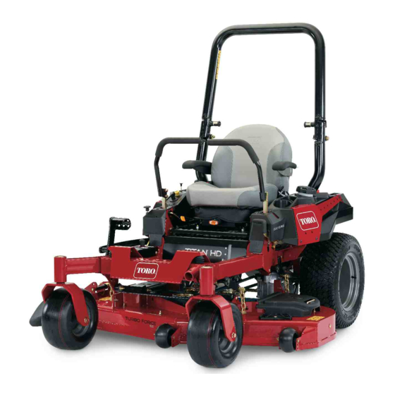
Toro TITAN HD 1500 Series Operator's Manual
122cm or 132cm
Hide thumbs
Also See for TITAN HD 1500 Series:
- Operator's manual (88 pages) ,
- Operator's manual (68 pages) ,
- Operator's manual (88 pages)

Related Manuals for Toro TITAN HD 1500 Series


Summary of Contents for Toro TITAN HD 1500 Series
- Page 1 Form No. 3421-131 Rev A 122cm or 132cm TITAN ® HD 1500 Series Riding Mower Model No. 74465TE—Serial No. 400000000 and Up Model No. 74466TE—Serial No. 400000000 and Up *3421-131* A Register at www.Toro.com. Original Instructions (EN)
-
Page 2: Figure
Important: If you are using a machine with a Toro register your product. engine above 1500 m (5,000 ft) for a continuous period, ensure that the High Altitude Kit has been... -
Page 3: Table Of Contents
Contents Safety ............... 4 General Safety ........... 4 Slope Indicator ........... 5 Safety and Instructional Decals ......6 Product Overview ........... 12 Controls ............12 Specifications ..........14 Before Operation ..........14 Before Operation Safety ........14 Adding Fuel ............15 Performing Daily Maintenance...... -
Page 4: Safety
Safety Replacing the Emissions-Air Intake Filter.............. 40 Fuel System Maintenance ........41 This machine has been designed in accordance with Replacing the Fuel Filter ........41 EN ISO 5395:2013. Servicing the Fuel Tank........41 Electrical System Maintenance ......42 Electrical System Safety ........42 General Safety Servicing the Battery......... -
Page 5: Slope Indicator
Slope Indicator g011841 Figure 4 This page may be copied for personal use. 1. The maximum slope you can operate the machine on is 15 degrees. Use the slope chart to determine the degree of slope of hills before operating. Do not operate this machine on a slope greater than 15 degrees. Fold along the appropriate line to match the recommended slope. -
Page 6: Safety And Instructional Decals
Safety and Instructional Decals Safety decals and instructions are easily visible to the operator and are located near any area of potential danger. Replace any decal that is damaged or missing. decaloemmarkt Manufacturer's Mark decal106-5517 1. Indicates the blade is identified as a part from the original 106-5517 machine manufacturer. - Page 7 decal112-3858 112-3858 1. Read the Operator's 3. Remove the key before Manual. adjusting the height of cut. 2. Read the instructions 4. Height-of-cut settings. before servicing or performing maintenance. decal116-8588 116-8588 1. Read the Operator’s Manual. 2. Rotate the drive release knob to loosen, slide the knob, and tighten.
- Page 8 decal117-3848 117-3848 1. Thrown object hazard—keep bystanders a safe distance away from the machine. 2. Thrown object hazard, mower—do not operate the machine without deflector, discharge cover, or grass collection system in place. 3. Cutting/dismemberment of hand or foot—stay away from moving parts;...
- Page 9 Manual. filler neck; warning—do not overfill the tank. decal136-8992 136-8992 1. Fuel—full 3. Fuel—empty 2. Fuel—50% decal131-1097 131-1097 Toro Engines Only 1. Oil drain decalptosymbols PTO Switch Symbols 1. PTO–disengage 2. PTO–engage decal136-9024 decaltransportlock 136-9024 Transport Lock 1. Read the Operator’s 4.
- Page 10 decalmotioncntrllh-126-6194 decalmotioncntrlrh-126-6183 Left Motion Control Right Motion Control 1. Machine speed 4. Neutral 1. Machine speed 4. Neutral 2. Fast 5. Reverse 2. Fast 5. Reverse 3. Slow 3. Slow decal136-1305 136-1305 1. Fast 4. Choke 2. Continuous-variable setting 5. Work light (optional) 6.
- Page 11 decal136-1720 136-1720 1. Cam lock 2. Cam unlock decal132-0871 132-0871 Note: This machine complies with the industry standard stability test in the static lateral and longitudinal tests with the maximum recommended slope indicated on the decal. Review the instructions for operating the machine on slopes in the Operator’s Manual as well as the conditions in which you would operate the machine to determine whether you can operate the machine in those conditions on that day and at that site.
-
Page 12: Product Overview
Key Switch Product Overview The key switch, used to start and shut off the engine, has 3 positions: O , and S . Refer to TART Starting the Engine (page 24). Choke Control Use the choke control to start a cold engine. Pull the choke control up to engage it. - Page 13 Contact your Authorized Service Dealer or Distributor or go to www.Toro.com for a list of all approved attachments and accessories. To best protect your investment and maintain optimal performance of your Toro equipment, count on Toro genuine parts.
-
Page 14: Specifications
Specifications Note: Specifications and design are subject to change without notice. Width: 122 cm mower deck 132 cm mower deck Without mower deck 121 cm (47-1/2 inches) 124 cm (49 inches) Deflector up 133 cm (53 inches) 144 cm (56-3/4 inches) Deflector down 160 cm (63-1/4 inches) 171 cm (67-1/4 inches) -
Page 15: Adding Fuel
Adding Fuel • Do not store the machine or fuel container where there is an open flame, spark, or pilot light, such as on a water heater or on other appliances. Recommended Fuel • Do not fill containers inside a vehicle or on a truck •... -
Page 16: Performing Daily Maintenance
Using the Note: Do not fill the fuel tank completely full. The empty space in the tank allows the fuel to Rollover-Protection System expand. (ROPS) WARNING To avoid injury or death from rollover, keep the roll bar in the fully raised, locked position and use the seat belt. -
Page 17: Using The Safety-Interlock System
Using the Safety-Interlock System WARNING If the safety-interlock switches are disconnected or damaged, the machine could operate unexpectedly, causing personal injury. • Do not tamper with the interlock switches. • Check the operation of the interlock switches daily and replace any damaged switches before operating the machine. -
Page 18: Positioning The Seat
Testing the Safety-Interlock Positioning the Seat System The seat can move forward and backward. Position the seat where you have the best control of the Service Interval: Before each use or daily machine and are most comfortable (Figure 11). Test the safety-interlock system before you use the machine each time. -
Page 19: Adjusting The Myride™ Suspension System
Adjusting the MyRide™ Adjust the rear-shock assemblies (Figure 13). Suspension System The MyRide™ suspension system adjusts to provide a smooth and comfortable ride. You can adjust the rear 2-shock assemblies to quickly and easily change the suspension system. Position the suspension system where you are most comfortable. -
Page 20: Using Attachments And Accessories
Accessories times. • Look behind and down before backing up to be Use only Toro approved attachments and accessories. sure of a clear path. If more than one accessory-mount kit (i.e., bucket • Use care when approaching blind corners, shrubs,... - Page 21 machine or a hand trimmer to mow the grass in these areas. • Avoid starting, stopping, or turning the machine on slopes. Avoid making sudden changes in speed or direction; turn slowly and gradually. • g229846 Do not operate a machine under any conditions Figure 15 where traction, steering, or stability is in question.
-
Page 22: Entering The Operator's Position
Entering the Operator’s Disengaging the Parking Brake Position Use the mower deck as a step to get into the operator’s position (Figure 17). g192635 g029797 Figure 19 Figure 17 Operating the Mower Operating the Parking Blade-Control Switch (PTO) Brake The blade-control switch (PTO) starts and stops the Always engage the parking brake when you stop the mower blades and any powered attachments. -
Page 23: Operating The Throttle
Disengaging the Blade-Control Operating the Choke Switch (PTO) Use the choke to start a cold engine. Pull up the choke knob to engage the choke before using the key switch (Figure 23). Push down the choke knob to disengage the choke after the engine has started (Figure 23). -
Page 24: Starting The Engine
Starting the Engine Shutting Off the Engine Note: A warm or hot engine may not require choking. CAUTION Important: Do not engage the starter for more Children or bystanders may be injured if they than 5 seconds at a time. Engaging the starter move or attempt to operate the machine while motor for more than 5 seconds can damage the it is unattended. -
Page 25: Using The Motion-Control Levers
Using the Motion-Control WARNING Levers The machine can spin very rapidly. You may lose control of the machine and cause personal injury or damage to the machine. • Use caution when making turns. • Slow the machine down before making sharp turns. -
Page 26: Adjusting The Height Of Cut
Driving Backward Adjusting the Height of Cut Move the levers to the center, unlocked position. Using the Transport Lock To go backward, slowly pull the motion-control levers rearward (Figure 28). The transport lock has 2 positions, and is used with the deck-lift pedal. -
Page 27: Adjusting The Anti-Scalp Rollers
Adjusting the Height-of-Cut Pin Adjusting the Anti-Scalp Rollers Adjust the height-of-cut from 38 to 127 mm (1-1/2 to 5 inches) in 6 mm (1/4 inch) increments by moving the height-of-cut pin into different hole locations. Whenever you change the height of cut, adjust the height of the anti-scalp rollers. -
Page 28: Using The Side Discharge
If a blade is It is best to cut only about a third of the grass blade. damaged or worn, replace it immediately with a Cutting more than that is not recommended unless genuine Toro replacement blade. -
Page 29: After Operation
Using the Drive-Wheel After Operation Release Valves After Operation Safety WARNING General Safety Hands may become entangled in the rotating drive components below the engine deck, • Clean grass and debris from the cutting units, which could result in serious injury. mufflers, and engine compartment to help prevent fires. -
Page 30: Transporting The Machine
Transporting the Machine Use a heavy-duty trailer or truck to transport the machine. Use a full-width ramp. Ensure that the trailer or truck has all the necessary brakes, lighting, and marking as required by law. Please carefully read all the safety instructions. Knowing this information could help you or bystanders avoid injury. - Page 31 If using a trailer, connect it to the towing vehicle and connect the safety chains. If applicable, connect the trailer brakes and lights. Lower the ramp, ensuring that the angle between the ramp and the ground does not exceed 15 degrees (Figure 35).
-
Page 32: Maintenance
• Check the parking brake adjustment. Every 500 hours • After the initial change—change the hydraulic-system filters and fluid when using Toro® HYPR-OIL™ 500 fluid (change it more often under severe conditions). • Check the battery charge. Monthly • Paint chipped surfaces. -
Page 33: Pre-Maintenance Procedures
• To ensure optimum performance and continued safety certification of the machine, use only genuine Toro replacement parts and accessories. Replacement parts and accessories made by other manufacturers could be dangerous, and such use could void the product warranty. -
Page 34: Removing The Sheet-Metal Guard
Removing the Sheet-Metal Lubrication Guard Greasing the Machine Loosen the 2 front bolts and remove the sheet-metal guard to access the mower belts and spindles (Figure Service Interval: Every 25 hours—Grease the front 39). Install the sheet-metal guard and tighten the bolts caster axles. -
Page 35: Engine Maintenance
Engine Maintenance Engine Safety • Shut off the engine before checking the oil or adding oil to the crankcase. • Keep your hands, feet, face, clothing, and other body parts away the muffler and other hot surfaces. g027800 Servicing the Air Cleaner Service Interval: Before each use or daily Note: Service the air cleaner more frequently (every... - Page 36 Servicing the Foam Air-Cleaner Installing the Air Cleaner Element Install the foam element over the paper element. Service Interval: Every 25 hours/Monthly (whichever Note: Ensure that you do not damage the comes first)—Clean the air-cleaner elements. foam element (more often in dusty, Align the holes of the filter into the manifold dirty conditions).
-
Page 37: Servicing The Engine Oil
Servicing the Engine Oil Engine-Oil Specifications Oil Type: Detergent oil (API service SF, SG, SH, SJ, or SL) Crankcase Capacity: 2.4 L (81 fl oz) with oil filter Viscosity: See the table below. g029683 Figure 44 Checking the Engine-Oil Level Service Interval: Before each use or daily Note: Check the oil when the engine is cold. - Page 38 Change the engine-oil filter (Figure 47). Note: Ensure that the oil-filter gasket touches the engine and then turn the filter an extra 3/4 turn. g027799 g027477 Figure 47 Slowly pour approximately 80% of the specified oil into the filler tube and slowly add the additional oil to bring it to the Full mark (Figure 48).
-
Page 39: Servicing The Spark Plug
g027478 Figure 49 Checking the Spark Plug Important: Do not clean the spark plug(s). Always replace the spark plug(s) when it has a black coating, worn electrodes, an oily film, or cracks. If you see light brown or gray on the insulator, the engine is operating properly. -
Page 40: Cleaning The Cooling System
Cleaning the Cooling Replacing the Emissions-Air Intake Filter System Park the machine on a level surface, disengage Service Interval: Every 500 hours the blade-control switch (PTO), and engage the Park the machine on a level surface, disengage parking brake. the blade-control switch (PTO), and engage the Shut off the engine, remove the key, and wait parking brake. -
Page 41: Fuel System Maintenance
Fuel System Maintenance DANGER In certain conditions, fuel is extremely flammable and highly explosive. A fire or explosion from fuel can burn you, others, and can damage property. • Perform any fuel-related maintenance when the engine is cold. Do this outdoors in an open area. -
Page 42: Electrical System Maintenance
Electrical System WARNING Incorrectly removing the cables from Maintenance battery could damage the machine and cables, causing sparks. Sparks can cause the battery gasses to explode, Electrical System Safety resulting in personal injury. • Disconnect the battery before repairing the •... - Page 43 Charging the Battery Installing the Battery Position the battery in the tray with the terminal WARNING posts opposite from the hydraulic tank (Figure 53). Charging the battery produces gasses that can explode. Install the positive (red) battery cable to the positive (+) battery terminal.
-
Page 44: Servicing The Fuses
Servicing the Fuses Drive System Maintenance The electrical system is protected by fuses. It requires no maintenance; however, if a fuse blows check the component and circuit for a malfunction or short. Checking the Seat Belt The fuses are located on the right console next to the seat (Figure 56). -
Page 45: Adjusting The Tracking
Adjusting the Tracking Disengage the blade-control switch (PTO). Drive to an open, flat area and move the motion-control levers to the N EUTRAL LOCK position. Move the throttle midway between the F positions. Move both motion-control levers forward until they both hit the stops in the T-slot. Check which way the machine tracks. -
Page 46: Checking The Tire Pressure
Checking the Tire Pressure Cooling System Maintenance Service Interval: Every 50 hours/Monthly (whichever comes first) Maintain the air pressure in the front and rear tires Cleaning the Engine Screen at 90 kPa (13 psi). Uneven tire pressure can cause uneven cut. Check the tires when they are cold to get Service Interval: Before each use or daily the most accurate pressure reading. -
Page 47: Brake Maintenance
Brake Maintenance Adjusting the Parking Brake Service Interval: Every 500 hours Note: Perform this procedure whenever you remove or replace a brake component. Park the machine on a level surface, disengage the blade-control switch (PTO), and engage the parking brake. Shut off the engine, remove the key, and wait g036752 for all moving parts to stop before leaving the... -
Page 48: Belt Maintenance
Figure 63 Remove the spring tension from the spring-loaded idler pulley. Refer to Figure Note: Use the spring removal tool (Toro Part No. 92-5771) to remove the spring from the mower-deck post (Figure 65). Remove the belt from the mower-deck pulleys and the clutch pulley. -
Page 49: Replacing The Hydraulic-Pump-Drive Belt
Raise the machine and support it with jack stands (Figure 68). g028279 Figure 65 Remove the clutch stop (Figure 67). 1. Spring-removal tool (Toro 4. Idler arm Part No. 92–5771) 2. Idler spring 5. Mower belt 3. Mower-deck post Install the idler spring (Figure 64). -
Page 50: Controls System Maintenance
Controls System Maintenance Adjusting the Control-Handle Position If the ends of the levers hit against each other, refer to Adjusting the Motion-Control Linkage (page 51). Adjusting the Height g036860 Figure 67 You can adjust the motion control levers higher or lower for maximum comfort. -
Page 51: Adjusting The Motion-Control Linkage
Adjusting the Tilt Disengage the blade-control switch (PTO), move the motion-control levers to the N EUTRAL LOCK Disengage the blade-control switch (PTO), move position, and engage the parking brake. the motion-control levers to the N EUTRAL LOCK position, and engage the parking brake. Shut off the engine, remove the key, and wait for all moving parts to stop before leaving the Shut off the engine, remove the key, and wait... -
Page 52: Hydraulic System Maintenance
3. Control plate System Shut off the machine. Hydraulic Fluid Specifications Remove the jumper wire from the wire harness Hydraulic Fluid Type: Toro ® HYPR-OIL ™ and plug the connector into the seat switch. hydraulic fluid (preferred) or Mobil 1 15W-50 oil. - Page 53 Every 500 hours—After the initial Carefully clean the area around the filters. change—change the hydraulic-system Important: filters and fluid when using Toro ® HYPR-OIL ™ Do not allow dirt to enter the 500 fluid (change it more often under severe hydraulic system, or contamination may conditions).
- Page 54 Bleeding the Hydraulic System Verify that the vent plugs are removed before adding the fluid. Raise the rear of machine and support it with Slowly pour the specified fluid through the jack stands (or equivalent support) just high expansion reservoir until fluid comes out of 1 enough to allow the drive wheels to turn freely.
-
Page 55: Mower Deck Maintenance
Mower Deck Maintenance Servicing the Cutting Blades g006530 Blade Safety Figure 76 1. Cutting edge 3. Wear/slot forming A worn or damaged blade can break, and a piece of 2. Curved area 4. Crack the blade could be thrown toward you or bystanders, resulting in serious personal injury or death. - Page 56 g014973 g014973 Figure 78 Figure 80 1. Blade (in position for measuring) 1. Opposite blade edge (in position for measuring) 2. Level surface 2. Level surface 3. Measured distance between blade and the surface (A) 3. Second measured distance between blade and surface (B) Rotate the same blade 180 degrees so that If the difference between A and B is greater the opposing cutting edge is now in the same...
-
Page 57: Leveling The Mower Deck
g000553 Figure 83 1. Blade 2. Balancer Repeat this procedure until the blade is balanced. Installing the Blades Install the blade onto the spindle shaft (Figure 81). Important: The curved part of the blade must point upward toward the inside of the mower to ensure proper cutting. - Page 58 Position the mower deck in the transport-lock position. Carefully rotate the blades from side to side. Measure between the blade tip and the flat surface (Figure 84). If the measurements are not within 5 mm (3/16 inch), adjust the leveling; continue with this procedure.
-
Page 59: Removing The Mower Deck
Loosen the locknuts (Figure 87) on all 4 corners and ensure that the mower deck is sitting securely on all 4 blocks. Remove any slack from the deck hangers and make sure the deck-lift foot lever is pushed back against the stop. Tighten the 4 locknuts. -
Page 60: Cleaning
Cleaning Cleaning under the Mower Deck Service Interval: Before each use or daily Park the machine on a level surface, disengage the blade-control switch (PTO), and engage the parking brake. Shut off the engine, remove the key, and wait for all moving parts to stop before leaving the g015594 operating position. -
Page 61: Storage
Storage tank. Follow mixing instructions from the stabilizer manufacturer. Do not use an alcohol-based stabilizer (ethanol or Storage Safety methanol). Note: A fuel stabilizer/conditioner is most • Let the engine cool before storing the machine. effective when mixed with fresh fuel and •... -
Page 62: Troubleshooting
Troubleshooting Problem Possible Cause Corrective Action The engine overheats. 1. The engine load is excessive. 1. Reduce the ground speed. 2. The oil level in the crankcase is low. 2. Add oil to the crankcase. 3. The cooling fins and air passages 3. - Page 63 Problem Possible Cause Corrective Action The machine does not drive. 1. The bypass valves are not closed tight. 1. Tighten the bypass valves. 2. The pump belt is worn, loose, or 2. Change the belt. broken. 3. The pump belt is off a pulley. 3.
-
Page 64: Schematics
Schematics g018479 Wire Diagram—Toro Engines (Rev. A) - Page 65 Notes:...
- Page 66 Notes:...
- Page 67 Notes:...
- Page 68 The Way Toro Uses Information Toro may use your personal information to process warranty claims, to contact you in the event of a product recall and for any other purpose which we tell you about. Toro may share your information with Toro's affiliates, dealers or other business partners in connection with any of these activities. We will not sell your personal information to any other company.