Table of Contents
Advertisement
Quick Links
USER MANUAL
NI cRIO-9031
Embedded CompactRIO Controller with Real-Time Processor and
Reconfigurable FPGA
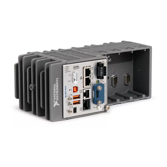
This document describes the features of the National Instruments cRIO-9031 and contains
information about mounting and operating the device.
RJ-45 Gigabit
Ethernet Port 1
RJ-45 Gigabit
Ethernet Port 2
USB 2.0
Host Port
USB 2.0
Host Port
USB 2.0
Device Port
cRIO-9031
E3825 1.33 GHz Dual-Core
System-On-Chip
Watchdog
Intel Atom
+
Xilinx
Kintex-7 FPGA
7K70T
+
Mini
DisplayPort
1 GB DDR3L
4 GB SATA
Disk-On-Chip
RJ-50
RS-232
Serial Port
RJ-50
RS-485/422 (DTE)
Serial Port
SD Card
Slot
Hardware
Data
Advertisement
Table of Contents

Related Manuals for National Instruments cRIO-9031


Summary of Contents for National Instruments cRIO-9031
- Page 1 USER MANUAL NI cRIO-9031 Embedded CompactRIO Controller with Real-Time Processor and Reconfigurable FPGA This document describes the features of the National Instruments cRIO-9031 and contains information about mounting and operating the device. Intel Atom RJ-45 Gigabit Mini Ethernet Port 1 DisplayPort E3825 1.33 GHz Dual-Core...
-
Page 2: Table Of Contents
Worldwide Support and Services.................... 40 Configuring the cRIO-9031 You can connect the cRIO-9031 to a host computer or network and configure the startup options using the USB device port or the RJ-45 Gigabit Ethernet port 1 or port 2. Refer to the getting started guide on ni.com/manuals... -
Page 3: Connecting The Crio-9031 To The Host Computer Or Network Using Ethernet
NI-cRIO-9031-1856AAA. Finding the cRIO-9031 on the Network (Static IP) Complete the following steps to find the cRIO-9031 on the network if the host computer is using a static IP address. The following instructions are for host computers running Windows 7. -
Page 4: Configuring Startup Options
Click Properties. Record the IP address, Subnet mask, and Default gateway address. You need these settings to configure the network settings of the cRIO-9031 and to restore the network settings of the host computer. You can also access these settings by opening the Start menu,... - Page 5 Table 1. cRIO-9031 Startup Options Startup Option Description Force Safe Mode Rebooting the cRIO-9031 with this setting on starts the cRIO-9031 without launching LabVIEW Real-Time or any startup applications. In safe mode, the cRIO-9031 launches only the services necessary for updating configuration and installing software.
-
Page 6: Crio-9031 Features
8. USB Device Port RJ-45 Gigabit Ethernet Ports The cRIO-9031 has two tri-speed RJ-45 Gigabit Ethernet ports. By default, both Ethernet ports are enabled and configured to obtain an IP address automatically. The Ethernet ports can be configured in MAX. - Page 7 19 Power Connector The cRIO-9031 has a power connector to which you can connect a primary and secondary power supply. The following table shows the pinout for the power connector. NI cRIO-9031 User Manual | © National Instruments | 7...
- Page 8 If you apply power to both the V1 and V2 inputs, the cRIO-9031 operates from the V1 input. If the input voltage to V1 is insufficient, the cRIO-9031 operates from the V2 input.
- Page 9 RS-232 Serial Port The cRIO-9031 has an RS-232 serial port that is implemented with an RJ-50, 10-position modular jack to which you can connect devices such as displays or input devices. Use the Serial VIs to read from and write to the serial port. Refer to the LabVIEW Help for information about the Serial VIs.
- Page 10 No Connect You can use the Ring Indicator (RI) on pin 2 to wake the controller from a low-power state. You can drive RI with a logic level high to wake the cRIO-9031. Refer to the specifications on ni.com/manuals for the RI wake voltage.
- Page 11 Using the Embedded UI to Access RT Target VIs topic in the LabVIEW Help. Caution Do not hot-swap Mini DisplayPort devices while the cRIO-9031 is in a hazardous location or connected to high voltages. The following table shows the pinout for the Mini DisplayPort.
- Page 12 ML_Lane0(p) Hot Plug The following adapters are available to connect the Mini DisplayPort to full-size DisplayPort, VGA, or DVI. The cRIO-9031 only supports DVI single link. Refer to the cRIO-9031 pricing page on ni.com for a complete list of cables and accessories.
- Page 13 21 Installing a Ferrite on the USB Cables You must install a ferrite around all USB cables connected to the USB host ports to ensure that the cRIO-9031 meets all EMC standards applicable to your country. What to Use •...
-
Page 14: Buttons
Caution Do not hot-swap USB devices while the cRIO-9031 is in a hazardous location or connected to high voltages. If the cRIO-9031 is not in a hazardous location, you can connect and disconnect USB devices without affecting operation. The following table shows the pinout for the USB device port. - Page 15 4. CMOS Reset Button Power Button The default behavior for the cRIO-9031 is to power on when you apply power to the controller and power off when you press and release the power button. The behavior of the power button can be configured in the BIOS.
-
Page 16: Leds
The cRIO-9031 has a general-purpose USER1 button that is user-defined. You can read the state of the USER1 button from your LabVIEW FPGA application. CMOS Reset Button The cRIO-9031 has a CMOS reset button that you can use to reset the CMOS and the BIOS. LEDs The cRIO-9031 provides the following LEDs. - Page 17 The cRIO-9031 is powered from the V1 input. Yellow Solid The cRIO-9031 is powered from the V2 input. — The cRIO-9031 is powered off. STATUS LED Indicators The following table describes the STATUS LED indicators. NI cRIO-9031 User Manual | © National Instruments | 17...
- Page 18 Remove any shorts and cycle power the cRIO-9031. If the problem persists, contact NI. — The cRIO-9031 is in run mode. Software is installed and the operating system is running. User LEDs You can define the USER1 and USER FPGA1 LEDs to meet the needs of your application.
- Page 19 — 10 Mbit/s data rate selected SD LED Indicators The cRIO-9031 has two LEDs that indicate the SD card drive mount status and activity. The following table lists SD LED indicators. Table 20. SD LED Indicators LED Color LED Pattern...
-
Page 20: Chassis Grounding Screw
Figure 6. cRIO-9031 Chassis Grounding Screw 1. Chassis Grounding Screw For EMC compliance, you must connect the cRIO-9031 to earth ground through the chassis ground screw. Use wire that is 1.31 mm (16 AWG) solid copper wire with a maximum length of 1.5 m (5 ft). -
Page 21: Cmos Battery
CMOS BATTERY IS DEAD battery is dead. The cRIO-9031 still starts, but the system clock is reset to the date and time of the BIOS release. The battery is not user-replaceable. If you need to replace the CMOS battery, contact NI. - Page 22 Torx T10 and T20. The other set is a tamper-resistant set of screws that require a security driver type, Torx T10H and T20H. Use the tamper-resistant set to help prevent unintended modification of the system. 22 | ni.com | NI cRIO-9031 User Manual...
-
Page 23: Module Immobilization Accessory Dimensions
Ensure that all the C Series modules are installed in the cRIO-9031 and the latches are locked in place. Remove the center right panel screw from the top and bottom of the cRIO-9031 using the Torx T10 driver. Slide the bracket into place, aligning the three clearance screw holes. -
Page 24: Mounting The Device
You can also mount the cRIO-9031 in other orientations, on a nonmetallic surface, on a 35-mm DIN rail, on a desktop, or in a rack. Mounting the cRIO-9031 in these or other configurations can reduce the maximum allowable ambient temperature and can affect the typical accuracy of modules in the cRIO-9031. -
Page 25: Dimensions
Mounting Requirements Your installation must meet the following requirements for cooling and cabling clearance. Allow 25.4 mm (1.00 in.) on the top and the bottom of the cRIO-9031 for air circulation, as shown in the following figure. NI cRIO-9031 User Manual | © National Instruments | 25... -
Page 26: Ambient Temperature
Ambient Temperature Measure the ambient temperature at each side of the cRIO-9031, 63.5 mm (2.50 in.) from the side and 38.1 mm (1.50 in.) forward from the rear of the cRIO-9031, as shown in the following figure. 26 | ni.com | NI cRIO-9031 User Manual... -
Page 27: Mounting The Device Directly On A Flat Surface
1. Location for measuring the ambient temperature Mounting the Device Directly on a Flat Surface For environments with high shock and vibration, NI recommends mounting the cRIO-9031 directly on a flat, rigid surface using the mounting holes in the cRIO-9031. What to Use •... - Page 28 Fasten the cRIO-9031 to the surface using the M4 screws appropriate for the surface. Screws must not exceed 8 mm of insertion into the cRIO-9031. Tighten the screws to a maximum torque of 1.3 N · m (11.5 lb · in.).
-
Page 29: Mounting The Crio-9031 On A Panel
Mounting the cRIO-9031 on a Panel You can use the NI panel mounting kit to mount the cRIO-9031 on a panel. What to Use • cRIO-9031 • Screwdriver, Phillips #2 • NI panel mounting kit, 157253-01 – Panel mounting plate –... -
Page 30: Mounting The Crio-9031 On A Din Rail
(5.47 in.) 25.4 mm (1.00 in.) 108.8 mm (4.26 in.) Mounting the cRIO-9031 on a DIN Rail You can use the NI DIN rail mounting kit to mount the cRIO-9031 on a standard 35-mm DIN rail. What to Use • cRIO-9031 •... - Page 31 Align the cRIO-9031 and the DIN rail clip. Fasten the DIN rail kit to the cRIO-9031 using the screwdriver and M4 × 10 screws. Tighten the screws to a maximum torque of 1.3 N · m (11.5 lb · in.).
-
Page 32: Mounting The Device On A Rack
Mounting the Device on a Rack You can use the following rack mount kits to mount the cRIO-9031 and other DIN rail- mountable equipment on a standard 482.6 mm (19 in.) rack. • NI Sliding Rack-Mounting Kit, 779102-1 • NI Rack-Mounting Kit, 781989-01... -
Page 33: Bios Configuration
BIOS Configuration Resetting the System CMOS and BIOS Settings The cRIO-9031 BIOS configuration information is stored in a nonvolatile memory location that does not require a battery to preserve the settings. Additionally, the BIOS optimizes boot time by saving specific system information to memory backed up by a battery (CMOS). -
Page 34: Power-On Self Test Warning Messages
Use the BIOS setup utility to change configuration settings and to enable special functions. The cRIO-9031 ships with configuration settings that work for most applications, but you can use the BIOS setup utility to change configuration settings to meet the needs of your application. -
Page 35: Main Setup Menu
System Time—This setting controls the time of day, which is stored in a battery-backed real-time clock. Most operating systems also include a way to change this setting. Use <+> and <-> in conjunction with <Enter> and <Tab> to change these values. NI cRIO-9031 User Manual | © National Instruments | 35... -
Page 36: Advanced Setup Menu
DC power is lost. Valid values are Stay Off and Turn On. The default value is Turn On. When set to Stay Off, the cRIO-9031 returns to the soft off power state after AC power is restored. When set to Turn On, the cRIO-9031 powers on when DC power is restored. -
Page 37: Boot Setup Menu
Disabled. • Boot Option Priorities—These settings specify the order in which the BIOS checks for bootable devices, including the local hard disk drive, removable devices such as USB NI cRIO-9031 User Manual | © National Instruments | 37... - Page 38 Option Priorities list displays the highest priority device. Optionally, each device can be disabled if the device is not used as a boot device. Floppy Drive BBS Priorities Submenu The Floppy Drive BBS Priorities submenu specifies the boot priority of floppy drive devices. 38 | ni.com | NI cRIO-9031 User Manual...
-
Page 39: Save & Exit Menu
The Save & Exit setup menu includes the following settings: • Save Changes and Reset—This setup utility then exits and reboots the cRIO-9031. Any changes made to BIOS settings are stored in NVRAM. The <F10> key also selects this option. -
Page 40: Worldwide Support And Services
NI trademarks. Other product and company names mentioned herein are trademarks or trade names of their respective companies. For patents covering NI products/technology, refer to the appropriate location: Help»Patents in your software, the file on your media, or the National Instruments Patent Notice at . You can find patents.txt ni.com/patents...
Need help?
Do you have a question about the cRIO-9031 and is the answer not in the manual?
Questions and answers