Table of Contents
Advertisement
Assembly Instructions
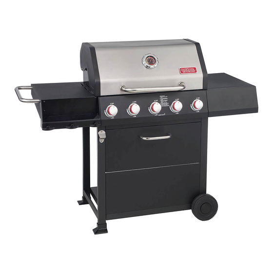
5-Burner Gas Grill
Model number: GR2323101-OG-00
Please keep this instruction manual for future reference
Email: customerservice@academy.com
Customer Service: 1-888-837-1380, 10:00am to 7:00pm, Monday thru Friday,
& User's Manual
Style number: 162195
Customer Service: 1-888-922-2336
7:00 am to 12:00 am CST (daily)
Live Chat at: www.academy.com
----------------------OR--------------------
CST
(Made in China)
PD: Austin McCurry 3/18/20
QA: GGMH 3/18/20
PS: NB 3/19/2020
Advertisement
Table of Contents

Related Manuals for Outdoor Gourmet GR2323101-OG-00


Summary of Contents for Outdoor Gourmet GR2323101-OG-00
- Page 1 QA: GGMH 3/18/20 PS: NB 3/19/2020 Assembly Instructions & User’s Manual 5-Burner Gas Grill Model number: GR2323101-OG-00 Style number: 162195 Please keep this instruction manual for future reference Customer Service: 1-888-922-2336 7:00 am to 12:00 am CST (daily) Live Chat at: www.academy.com Email: customerservice@academy.com...
-
Page 2: Table Of Contents
Table of Contents Warnings 2–7 --------------------------------------------------------------------------------------------- Tools Required ----------------------------------------------------------------------------------- Product Diagram ------------------------------------------------------------------------------- Parts List 9–11 -------------------------------------------------------------------------------------------- Hardware -------------------------------------------------------------------------------------------- Replacement Part List 13–14 ---------------------------------------------------------------------- Assembly Instructions 15–24 ---------------------------------------------------------------------- Leak Test 25–26 -------------------------------------------------------------------------------------------- Lighting Instructions 27–28 ------------------------------------------------------------------------- Care and Maintenance 29–31 -------------------------------------------------------------------- Trouble Shooting ------------------------------------------------------------------------------- Warranty Information... -
Page 3: Warnings
Warnings SAFETY LABELS DANGER: Indicates an imminent hazardous situation which if not avoided will result in death or serious injury. WARNING: Be alert to the possibility of serious bodily injury if the instructions are not followed. Be sure to read and carefully follow all of the messages. CAUTION: Indicates a potentially hazardous situation, which, if not avoided, may result in minor or moderate injury. - Page 4 Warnings DANGER (a) Do not store a spare LP-gas cylinder under or near this appliance; (b) Never fill the cylinder beyond 80 percent full; (c) If the information in (a) and (b) is not followed exactly, a fire causing death or serious injury may occur.
- Page 5 Warnings ⚫ Keep a fire extinguisher on hand intended for use with gas products. Refer to your local authority to determine proper size and type. ⚫ Grill is hot when in use. To avoid burns: ⚫ DO NOT attempt to move the grill. ⚫...
- Page 6 Warnings ⚫ If the outdoor cooking gas appliance is not in use, the gas must be turned off at the supply cylinder(s). ⚫ The LP cylinder must be stored outdoors out of the reach of children and MUST NOT be stored in a building, garage, shed, breezeway, or any other enclosed area.
- Page 7 Warnings INSTALLING GAS CYLINDER 1. Check that the cylinder valve is closed by turning the knob clockwise. 2. Place the cylinder into tank hole of the cart base properly. Locate the cylinder so that the valve opening faces the right side table and verify that the hose is not kinked/damaged.
-
Page 8: Tools Required
Warnings TO DISCONNECT LP CYLINDER: Turn the burner valves off. Turn the tank valve off fully (turn clockwise to stop). Detach the regulator assembly from the tank valve by turning the quick coupling nut counterclockwise. CAUTION ⚫ When installing LP cylinders, the pressure regulator and hose supplied by the manufacturer MUST be used with the appropriate cylinder. -
Page 9: Product Diagram
Product Diagram Page 8 of 33 20200109-Ver.1.0... -
Page 10: Parts List
Parts List Warming Rack 1 pc Cooking Grate 3 pcs Flame Tamer 5 pcs Grill Body Assembly 1 pc Thermometer 1 pc Side Handle 1 pc Left Side Table 1 pc Left Side Condiment 1 pc Tray Grease Cup 1 pc Page 9 of 33 20200109-Ver.1.0... - Page 11 Parts List Right Side Table 1 pc Right Side Table Panel 1 pc Thermometer Bezel 1 pc Left Cart Assembly 1 pc Front Foot Pad 1 pc Rear Foot Pad 1 pc Tank Blocking Bar 1 pc Bottle Opener 1 pc Right Cart Assembly 1 pc Page 10 of 33...
- Page 12 Parts List Accessory Tray 1 pc Wheel Assembly 2 pcs Front Cart Supporting 1 pc Beam Front Cart Upper Panel 1 pc Front Cart Lower Panel 1 pc Front Cart Panel Handle 1 pc Cart Base 1 pc Page 11 of 33 20200109-Ver.1.0...
-
Page 13: Hardware
Hardware List M5x10mm Bolt 13 pcs M5x12mm Bolt 6 pcs M6x10mm Bolt (Silver) 2 pcs M6x10mm Bolt (Black) 8 pcs M6x12mm Bolt 18 pcs M6 Nut 4 pcs Cotter Pin 2 pcs Washer 2 pcs Thermometer Washer 2 pcs Thermometer Nut 1 pc M6 Washer 2 pcs... -
Page 14: Replacement Part List
Replacement Part List (I) Page 13 of 33 20200109-Ver.1.0... - Page 15 Replacement Part List (II) Part Number Component Part Name Part Number Component Part Name MET-5B0001 Warming Rack MET-5B0002 Cooking Grate MET-6B0003 Flame Tamer MET-5B0003 Grill Body – Lid MET-5B0004 Grill Body – Control Panel GAS-5B0001 Grill Body – Hose & Regulator Assembly MET-6B0014 Grill Body –...
-
Page 16: Assembly Instructions
Assembly Instructions Step 1. Attach the Front Foot Pad (14) and Rear Foot Pad (15) to the Left Cart Assembly (13). Step 2. Disassemble the Cotter Pin (G), Washer (H) from the Wheel Axle (20b). Attach the Wheel (20a) on the Right Cart Assembly (18) using Washer (H), Cotter Pin (G) and Wheel Axle (20b) as shown. - Page 17 Assembly Instructions Step 3. Attach the Cart Base (25) to the left cart assembly and right cart assembly using 4 pcs M5x10 Bolts (A). Hardware: #A – 4 pcs Step 4. Attach the Front Cart Supporting Beam (21) to cart assembly using 4 pcs M5x10 bolts (A).
- Page 18 Assembly Instructions Step 5. Attach the Front Cart Lower Panel (23) to cart assembly using 4 pcs M5x10 bolts (A). Hardware: #A – 4 pcs Step 6. Attach the Front Cart Upper Panel (22) to cart assembly using 4 pcs M5x12 bolts (B). Hardware: #B –...
- Page 19 Assembly Instructions Step 7. Attach the Front Cart Panel Handle (24) to the front cart upper panel using 2 pcs M5x12 bolts (B). Hardware: #B – 2 pcs Step 8. Insert the Accessory Tray (19) into the fixing slots at the back of front cart upper panel.
- Page 20 Assembly Instructions Step 9. Attach the Tank Blocking Bar (16) to the left cart assembly by using 1 pc M5x10 bolts (A) and 1 pc M6x10 bolts (D) on cart base. Hardware: #A – 1 pc #D – 1 pc Step 10.
- Page 21 Assembly Instructions Step 11. This step needs two people to complete! Put the Grill Body assembly (4) carefully on top of the cart assembly. Secure the part as shown with 4 pcs of M6x10mm bolts (D). Be careful to support the grill body and cart assembly during this step.
- Page 22 Assembly Instructions Step 13. Attach the Left Side Condiment Tray (8) to the Left Side Table (7) using 4 pcs M6x12 bolts (E) and 4 pcs M6 Nut (F). Hardware: #E – 4 pcs #F – 4 pcs Step 14. Attach the Side Handle (6) to left side table assembly using 2 pcs pre-attached M6x12 bolts...
- Page 23 Assembly Instructions Step 15. Remove 2 pcs of M6x12mm bolt (E) from left side of the control panel. Loosen 4 pcs of the pre-attached bolts M6x12 bolts (E) from left side of the grill body until 3/16” clearance as shown on the image. Position the holes on the left side table assembly through the bolts at grill body as shown.
- Page 24 Assembly Instructions Step 17. Remove 2 pcs of M6x12mm bolt (E) from right side of the control panel. Loosen 4 pcs pre-attached bolts M6x12 bolts (E) on right side of the grill body until 3/16” clearance as shown on the image. Position the holes on the right side table assembly through the bolts at grill body as shown.
- Page 25 Assembly Instructions Step 19. Position the Grease Cup (9) into the holding bracket at the bottom of the grill body. Step 20. Your unit is fully assembled! Make sure to read and follow the complete Instruction Manual before using this appliance.
-
Page 26: Leak Test
Leak Test GENERAL Although all gas connections on the grill are leak tested at the factory prior to shipment, a complete gas tightness check must be performed at the installation site due to possible mishandling in shipment, or excessive pressure unknowingly being applied to the unit. Periodically check the entire system for leaks following the procedures listed below. - Page 27 Leak Test 3. If a leak is present, immediately turn off the gas supply and tighten the leaky fittings. 4. Turn the gas back on and recheck. 5. Should gas continue to leak from any of the fittings, turn off the gas supply and contact customer service department at 1-888-922-2336, 7:00 am to 12:00 am CST (daily) or 1-888-837-1380, Mon to Fri, 10:00am –...
-
Page 28: Lighting Instructions
Lighting Instructions BEFORE LIGHTING WARNING ⚫ Inspect the gas supply hose prior to turning the gas ON. ⚫ If there is evidence of cuts, wear, or abrasion, the hose must be replaced prior to use. ⚫ Do not use the grill if the odor of gas is present. ⚫... - Page 29 Lighting Instructions To turn burners off, turn the control knobs clockwise to “HI” then press down the knob and continue to turn clockwise until they lock in the “OFF” position. USING MATCH HOLDER TO LIGHT BURNER Turn OFF all burner valves. Make sure the lid is open.
-
Page 30: Care And Maintenance
Care and Maintenance CAUTION ⚫ Keep outdoor cooking gas appliance area clear and free from combustible materials, gasoline and other flammable vapors or liquids. ⚫ Do not obstruct the flow of combustible and ventilation air. ⚫ Keep the ventilation openings of the cylinder enclosure free and clear of debris. ⚫... - Page 31 Care and Maintenance You should inspect the burners at least once a year or immediately after any of the following conditions occur: The smell of gas in conjunction with the burner flames appearing yellow. The grill does not reach temperature. The grill heats unevenly.
- Page 32 Care and Maintenance TO REINSTALL THE MAIN BURNERS: 1. Insert the burner into the burner valve. 2. Firmly seat the valve orifice into the burner tube. Make sure the Valve orifice is inserted STRAIGHTLY into the burner tube. 3. Align the burner with the fixing slot at firebox, insert the cotter pin to the hole of the fixing slot. MAIN BURNER REPLACEMENT: 1.
-
Page 33: Trouble Shooting
Trouble Shooting Problem: Possible Causes: Corrective Actions: Burner cannot 1. LP cylinder fuel is used up. 1. Change a new full LP cylinder. light. 2. Bad electrode spark. 2. Check to see if the spark will 3. Burner may not be properly match with the vents of burner. -
Page 34: Warranty Information
Warranty Information Manufacturer warrants this Product to be free from defects in workmanship and materials for a period of 1 year from the date of purchase, PROVIDED claims are submitted, in writing, with proof of purchase. If any part of this item fails because of a manufacturing defect within the Limited Warranty Period, Manufacturer offers to replace such part(s) provided that such parts have not been improperly repaired, altered, or tampered with or subject to misuse, abuse or exposed to corrosive conditions.
Need help?
Do you have a question about the GR2323101-OG-00 and is the answer not in the manual?
Questions and answers