Table of Contents
Advertisement
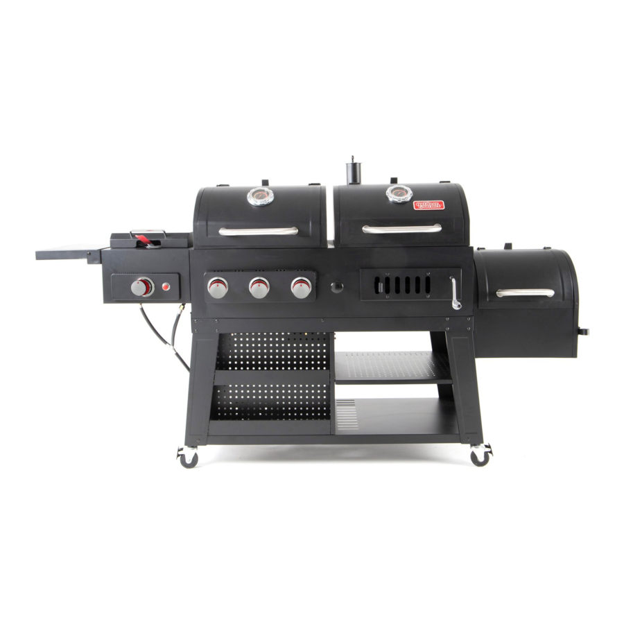
& User's Manual
Combo Grill
Model number: GR2333401-OG-00
Ref. style: 163886
Please keep this instruction manual for future reference
Customer Service: 1-888-922-2336
7:00 am to 12:00 am CST (daily)
Live Chat at: www.academy.com
Email: customerservice@academy.com
----------------------OR--------------------
Customer Service: 1-888-837-1380, 10:00am to 7:00pm, Monday thru Friday,
CST
(Made in China)
Advertisement
Table of Contents

Related Manuals for Outdoor Gourmet GR2333401-OG-00


Summary of Contents for Outdoor Gourmet GR2333401-OG-00
- Page 1 Assembly Instructions & User’s Manual Combo Grill Model number: GR2333401-OG-00 Ref. style: 163886 Please keep this instruction manual for future reference Customer Service: 1-888-922-2336 7:00 am to 12:00 am CST (daily) Live Chat at: www.academy.com Email: customerservice@academy.com ----------------------OR-------------------- Customer Service: 1-888-837-1380, 10:00am to 7:00pm, Monday thru Friday,...
- Page 2 Table of Contents Warnings 2–11 --------------------------------------------------------------------------------------------- Tools Required ----------------------------------------------------------------------------------- Product Diagram ------------------------------------------------------------------------------- Parts List 13–18 -------------------------------------------------------------------------------------------- Hardware List 19–20 ------------------------------------------------------------------------------------ Replacement Part List 21–22 ---------------------------------------------------------------------- Assembly Instructions 23–40 ---------------------------------------------------------------------- Leak Test 41–42 -------------------------------------------------------------------------------------------- LP Lighting Instructions 43–44 -------------------------------------------------------------------- Charcoal Grill Operation 45–47 ------------------------------------------------------------------ Care and Maintenance...
- Page 3 Warnings SAFETY LABELS DANGER: Indicates an imminent hazardous situation which, if not avoided, will result in death or serious injury. WARNING: Indicates a potentially hazardous situation which, if not avoided, could result in death or serious injury. CAUTION: Indicates a potentially hazardous situation which, if not avoided, may result in minor or moderate injury.
- Page 4 Warnings WARNING The appliance is designed for outdoor use only. Do NOT operate in a building, garage, or any other enclosed area. Do NOT install this appliance in or on boats. This appliance is not intended to be installed in or on recreational vehicles.
- Page 5 Warnings ⚫ When cooking, the appliance must be on a level, stable noncombustible surface in an area clear of combustible material. An asphalt surface (blacktop) may not be acceptable for this purpose. ⚫ Do not leave the appliance unattended. Keep children and pets away from the appliance at all times.
- Page 6 Warnings GENERAL WARNINGS FOR SIDE COOKER WARNING ⚫ FOR OUTDOOR USE ONLY. ⚫ This appliance is NOT for frying turkey. ⚫ This appliance is NOT intended for commercial use. ⚫ When cooking with oil or grease, the thermometer provided MUST be used. Follow instructions in this manual for proper installation and use of the thermometer.
- Page 7 Warnings GENERAL WARNINGS FOR CHARCOAL GRILL WARNING ⚫ FOR OUTDOOR USE ONLY. DO NOT operate the grill indoors or in an enclosed area because of carbon monoxide poisoning that can lead to personal injury or death. ⚫ Never place more than 3.3 lb. (1.5 kg) of charcoal inside the main charcoal grill; 1.5 lb. (0.68kg) in the side smoker.
- Page 8 Warnings ⚫ When grilling, grease from meat may drip into the charcoal and cause a grease fire. If this should happen, close the lid to suffocate the flame. Do not use water to extinguish grease fires. ⚫ Extinguished coals and ashes should be placed a safe distance from all structures and combustible materials.
- Page 9 Warnings USE OF LP GAS CYLINDER AND INSTALLATION BEFORE INSTALLING: The installation must conform with local codes or, in the absence of local codes, with either the National Fuel Gas Code, ANSI Z223.1/NFPA 54, Natural Gas and Propane Installation Code, CSA B149.1, or Propane Storage and Handling Code, B149.2 or the Standard for Recreational Vehicles, ANSI A 119.2/NFPA 1192, and CSA Z240 RV Series, Recreational Vehicle Code, as applicable.
- Page 10 Warnings DANGER ⚫ DO NOT connect this grill to an existing #510 POL cylinder valve with Left hand threads. The Type 1 valve can be identified with the large external threads on the valve outlet. ⚫ DO NOT connect to a propane cylinder exceeding its capacity. ⚫...
- Page 11 Warnings INSTALLING GAS CYLINDER Check that the cylinder valve is closed by turning the knob in clockwise. Place the cylinder into cylinder fixture. Place cylinder such that the valve opening faces the side burner in such a way that the hose is not kinked/damaged. WARNING: Keep the fuel supply hose away from any heated surfaces.
- Page 12 Warnings TO DISCONNECT LP CYLINDER: Turn the burner valves off. Turn the tank valve off fully (turn clockwise to stop). Detach the regulator assembly from the tank valve by turning the quick coupling nut counterclockwise. CAUTION ⚫ When installing LP cylinders the pressure regulator and hose supplied by the manufacturer MUST be used with the appropriate cylinder.
- Page 13 Product Diagram Page 12 of 53 20201209-Ver.1.0...
- Page 14 Parts List Warming Rack 2 pcs Cooking Grate 4 pcs Flame Tamer 3 pcs Thermometer 2 pcs Thermometer Bezel 2 pcs Chimney Stack 1 pc Assembly Lid Stopper 3 pcs Grill Body Assembly 1 pc Page 13 of 53 20201209-Ver.1.0...
- Page 15 Parts List Lid Handle Assembly 2 pcs Crank 1 pc Grease Tray 1 pc Ash Tray 1 pc Temperature Gauge 1 pc Basket 1 pc Basket Handle 1 pc 1 pc Page 14 of 53 20201209-Ver.1.0...
- Page 16 Parts List Side Burner Grate 1 pc Side Burner Lid Handle 1 pc Left Side Shelf 1 pc Left Side Shelf Rear 1 pc Bracket Left Side Shelf Front 1 pc Bracket Smoker Cooking Grate 2 pcs Smoker Charcoal Tray 1 pc Smoker Body Assembly 1 pc...
- Page 17 Parts List Smoker Lid Handle 1 pc Assembly Smoker Air Vent 1 pc Smoker Door Lock 1 pc Cart Rear Brace 1 pc Tank Heat Shield 1 pc Grease Cup 1 pc Grease Cup Holder 1 pc Cart Leg Brace 1 pc Page 16 of 53 20201209-Ver.1.0...
- Page 18 Parts List Left Front Leg 1 pc Left Rear Leg 1 pc Locking Caster 4 pcs Cart Middle Panel 1 pc Cart Rack 1 pc Cart Front Brace 1 pc Right Front Leg 1 pc Right Rear Leg 1 pc Page 17 of 53 20201209-Ver.1.0...
- Page 19 Parts List Accessary Tray Rear 1 pc Panel Upper Accessary Tray 1 pc Panel Lower Accessary Tray 1 pc Panel Tank Fixture 1 pc Cart Bottom Panel 1 pc Charcoal Tray 1 pc Charcoal Tray Bracket 1 pc Page 18 of 53 20201209-Ver.1.0...
- Page 20 Hardware List Phillips Head Screwdriver 1 pc M4x10mm Bolt 14 pcs M6x10mm Bolt 79 pcs Hex Nut Wrench 1 pc LR6/AA Battery 1 pc M6x15mm Bolt 16 pcs Hinge Pin 4 pcs Plastic Rivet 3 pcs M6 Nut 19 pcs Cotter Pin 5 pcs M6 Locking Nut...
- Page 21 Thermometer Nut 2 pcs M5x10mm Bolt 2 pcs M6x20mm Bolt 2 pcs Rotary Sleeve 2 pcs M5x12mm Bolt (silver) 3 pcs M5 Washer (silver) 3 pcs M5 Spring Washer (silver) 3 pcs M5 Nut (silver) 3 pcs Note: Hardware L, M, N, O, P, Q, R, S, and T have been pre-attached on the related components.
- Page 22 Replacement Part List (I) Page 21 of 53 20201209-Ver.1.0...
- Page 23 Replacement Part List (II) Part Number Component Part Name Part Number Component Part Name MET-3B0165 Warning Rack MET-3B0011 Cooking Grate MET-3B0166 Flame Tamer THE-6B0001 Thermometer THE-3B0005 Thermometer Bezel MET-3B0167 Chimney Stack MET-3B0034 Chimney Stack Cover MET-3B0168 Lid Stopper Grill Body – Side Burner Grill Body –...
- Page 24 Assembly Instructions Step 1. Attach the Left Front Leg (33), Left Rear Leg (34), Right Front Leg (39) and Right Rear Leg (40) to the Cart Bottom Panel (45) by using 8 pcs M6X10 Bolts (C). Hardware: #C – 8 pcs Step 2.
- Page 25 Assembly Instructions Step 3. Attach the Cart Middle Panel (36) to the cart assembly by using 2 pcs M6x10 Bolts (C). Hardware: #C – 2 pcs Step 4. Attach the Lower Accessary Tray Panel (43) to the cart assembly by using 4 pcs M4X10 Bolts (B).
- Page 26 Assembly Instructions Step 5. Attach the Accessary Tray Rear Panel (41) to the cart assembly by using 2 pcs M6X10 Bolts (C). Hardware: #C – 2 pcs Step 6. Attach the Upper Accessary Tray Panel (42) to the cart assembly by using 6 pcs M4X10 Bolts (B).
- Page 27 Assembly Instructions Step 7. Attach the Cart Rack (37) to the cart assembly by using 4 pcs M6X10 Bolts (C). Hardware: #C – 4 pcs Step 8. Attach the Cart Front Brace (38) to the cart assembly by using 13 pcs M6X10 Bolts (C). Hardware: #C –...
- Page 28 Assembly Instructions Step 9. Attach the Cart Rear Brace (28) to the cart assembly by using 11 pcs M6X10 Bolts (C). Hardware: #C – 11 pcs Step 10. Attach the Cart Leg Brace (32) to the cart assembly by using 8 pcs M6X10 Bolts (C).
- Page 29 Assembly Instructions Step 11. Attach the Tank Fixture (44) to the cart assembly by using 3 pcs Plastic Rivets (H) . Hardware: #H – 3 pcs Step 12. Attach the Grease Cup Holder (31) to the cart assembly by using 3 pcs M6X10 Bolts (C) . Hardware: #C –...
- Page 30 Assembly Instructions Step 13. Attach the Tank Heat Shield (29) to the cart assembly by using 4 pcs M4X10 Bolts (B). Hardware: #B – 4 pcs Step 14. Tighten all the bolts on the cart. Lock all 4 locking casters to prevent the unit moving by stepping the pad downwards.
- Page 31 Assembly Instructions Step 15. This step needs two people to complete! Put the Grill Body Assembly (8) carefully at the top of the cart assembly. Secure the part as shown with 7 pcs of M6x10mm bolts (C). Be careful to support the grill body and cart assembly during this step.
- Page 32 Assembly Instructions Step 17. Attach the Lid Stopper (7) to the grill body and smoker body assembly by using 6 pcs of M6x10mm bolts (C) and 6 pcs of M6 Nut (I). Make sure the lid stoppers are positioned at right direction as shown.
- Page 33 Assembly Instructions Step 19. Attach the Charcoal Tray Bracket (47) to the charcoal side of the grill body assembly by using the 6 pcs M6x15mm bolts (F) as shown. Hardware: #F – 6 pcs Step 20. Attach the Charcoal Tray (46) to the Charcoal Tray Bracket (47) by using the 4 pcs Hinge Pins (G) and 4 pcs Cotter Pin...
- Page 34 Assembly Instructions Step 21. Rotate the Crank (10) into the crank holder on the charcoal side of grill body assembly then using 1 pc of Cotter Pin (J) to fix the crank as shown. Hardware: #J – 1 pc Step 22. Disassemble the Thermometer Washers (L) and Thermometer Nuts (M)
- Page 35 Assembly Instructions Step 23. Attach the Lid Handles (9a) and Lid Handle Bezels (9b) to the gas and charcoal lids by using 4 pcs pre-attached M6x15 bolts (F). Attach the Smoker Lid Handle (25a) and Lid Handle Bezel (9b) to the smoker lid by using 2 pcs pre-attached M6x15 bolts (F).
- Page 36 Assembly Instructions Step 25. Attach the Smoker Door Lock (27) to the smoker door by using 1 pc M6x10 Bolt (C) and 1 pc M6 Locking Nut (K). Hardware: #C – 1 pc #K – 1 pc Step 26. Attach the Smoker Air Vent (26) to the smoker door by using 1 pc M6x10 Bolt (C) and 1 pc M6 Locking Nut (K).
- Page 37 Assembly Instructions Step 27. Attach the Left Side Shelf Rear Bracket (20) and Left Side Shelf Front Bracket (21) to the side burner assembly by using 4 pcs M6x15 Bolt (F). Hardware: #F – 4 pcs Step 28. 2 sets of M6x20 Bolts (O), Rotary Sleeves (P) and M6 Nuts (I) have pre-attached on the left side shelf brackets.
- Page 38 Assembly Instructions Step 29. Remove 3 pcs pre-assembled M5 x 12 Bolts (Silver) (Q), 3 pcs M5 Washers (Silver) (R), 3 pcs M5 Spring Washers (Silver) (S) and 3 pcs M5 Nuts (Silver) (T) from the Basket Handle (15). Attach the Basket Handle (15) to the Basket (14) by using the removed bolts, washers, spring...
- Page 39 Assembly Instructions Step 31. Position the Grease Cup (30) into the grease cup holder at the cart middle panel. Step 32. Place the Smoker Cooking Grate (22) and Smoker Charcoal Tray (23) on the smoker body assembly as shown. Page 38 of 53 20201209-Ver.1.0...
- Page 40 Assembly Instructions Step 33. Place the Flame Tamers (3) on the grill as shown. Step 34. Place the Warming Racks (1) and Cooking Grates (2) on the grill as shown. Remember to check that the rear wire guard of the warming rack sits on the warming rack bracket in the fire box.
- Page 41 Assembly Instructions Step 35. Install a LR6/AA Battery (E) into the igniter. Hardware: #E – 1 pc Step 36. Your unit is fully assembled! Make sure to read and follow the complete Instruction Manual before using this appliance. Remark: Fold down the left side shelf when not in use.
- Page 42 Leak Test GENERAL Although all gas connections on the grill are leak tested at the factory prior to shipment, a complete gas tightness check must be performed at the installation site due to possible mishandling in shipment, or excessive pressure unknowingly being applied to the unit. Periodically check the entire system for leaks following the procedures listed below.
- Page 43 Leak Test 3. If a leak is present, immediately turn off the gas supply and tighten the leaky fittings. 4. Turn the gas back on and recheck. 5. Should gas continue to leak from any of the fittings, turn off the gas supply and contact customer service department at 1-888-922-2336, 7:00 am to 12:00 am CST (daily) or 1-888-837-1380, Mon to Fri, 10:00am –...
- Page 44 LP Lighting Instructions BEFORE LIGHTING WARNING ⚫ Inspect the gas supply hose prior to turning the gas ON. ⚫ If there is evidence of cuts, wear, or abrasion, the hose must be replaced prior to use. ⚫ Do not use the grill if the odor of gas is present. ⚫...
- Page 45 LP Lighting Instructions USING MATCH HOLDER TO LIGHT BURNER Turn off all burner valves. Make sure the lid is open. Place a lighted match on the match holder and hold next to the burner. Turn the control knob(s) to the “HI” position. Burner should light immediately. If the burner does not light in 5 seconds, turn the knob off and wait for 5 minutes then repeat above procedures.
- Page 46 Charcoal Grill Operation Curing your grill Prior to your first use of the Grill, follow the instructions below carefully to cure your grill. Curing your grill will minimize damage to the exterior finish as well as rid the grill of paint odor that can impart unnatural flavors to the first meal prepared on the grill.
- Page 47 Charcoal Grill Operation this manual). If using a Charcoal Chimney Starter, follow “Operating Instruction Step 4” or follow all manufacturer’s warnings and instructions regarding the use of their product. Start with 3.3 lb. (1.5 kg) of charcoal in the main charcoal grill. For smoking, start with 1.5 lb. (0.68kg) of charcoal in the side smoker.
- Page 48 Charcoal Grill Operation Regulating Heat By adjusting the position of the charcoal tray, the temperature of grill can be regulated. To increase the heat, move the charcoal towards the cooking grates. Lowering it will decrease the temperature. Rotate the crank to raise or lower the position of the charcoal tray to achieve the desired temperature.
- Page 49 Care and Maintenance You should inspect the burners at least once a year or immediately after any of the following conditions occur: The smell of gas in conjunction with the burner flames appearing yellow. The grill does not reach temperature. The grill heats unevenly.
- Page 50 Care and Maintenance MAIN BURNER REPLACEMENT: 1. Remove the cooking grates and flame tamers. 2. Remove the burner cotter pin as shown. Remove the carry over and the burner fixing pin. 3. Remove the fixing bolt of the ignition electrode & wire. 4.
- Page 51 Care and Maintenance SIDE BURNER REPLACEMENT: 1. Open the side burner lid and remove the side burner grate. 2. Remove the burner fixing bolt at the bottom of side burner assembly as shown. 3. Remove the ignition wire on the side burner. 4.
- Page 52 Care and Maintenance ⚫ Cure your grill periodically throughout the year to protect against excessive rust. ⚫ To protect your grill from excessive rust, the unit must be properly cured and covered at all times when not in use. ⚫ Wash cooking grates with hot, soapy water, rinse well and dry.
- Page 53 Trouble Shooting Problem: Possible Causes: Corrective Actions: Burner cannot 1. LP cylinder fuel is used up. 1. Change a new full LP cylinder. light. 2. Bad electrode spark. 2. Check to see if the spark will 3. Burner may not be properly match with the vents of burner.
- Page 54 Warranty Information Manufacturer warrants this Product to be free from defects in workmanship and materials for a period of 1 year from the date of purchase, PROVIDED claims are submitted, in writing, with proof of purchase. If any part of this item fails because of a manufacturing defect within the Limited Warranty Period, Manufacturer offers to replace such part(s) provided that such parts have not been improperly repaired, altered, or tampered with or subject to misuse, abuse or exposed to corrosive conditions.
Need help?
Do you have a question about the GR2333401-OG-00 and is the answer not in the manual?
Questions and answers