Table of Contents
Advertisement
Quick Links
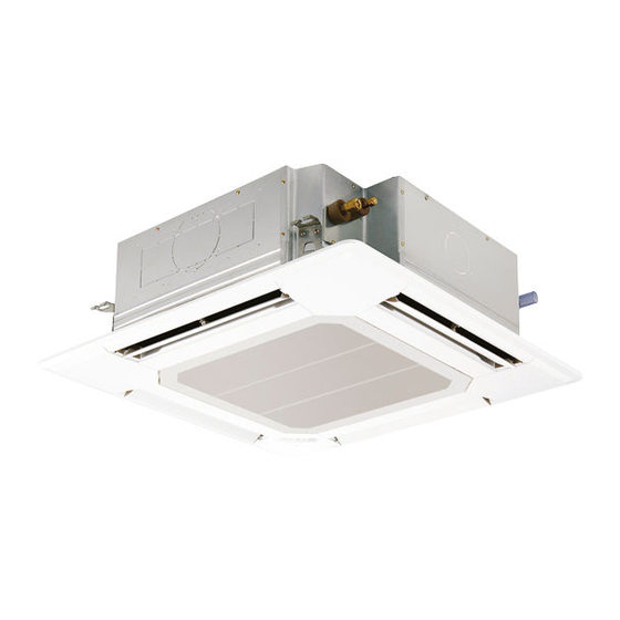
SPLIT-TYPE, HEAT PUMP AIR CONDITIONERS
TECHNICAL & SERVICE MANUAL
Indoor unit
[Model names]
[Service Ref.]
PLFY-M20VEM-E.UK
PLFY-M20VEM-E
PLFY-M20VEM-ET.UK
PLFY-M20VEM-ET
PLFY-M25VEM-E.UK
PLFY-M25VEM-E
PLFY-M25VEM-ET.UK
PLFY-M25VEM-ET
PLFY-M32VEM-E.UK
PLFY-M32VEM-E
PLFY-M32VEM-ET.UK
PLFY-M32VEM-ET
PLFY-M40VEM-E.UK
PLFY-M40VEM-E
PLFY-M40VEM-ET.UK
PLFY-M40VEM-ET
PLFY-M50VEM-E.UK
PLFY-M50VEM-E
PLFY-M50VEM-ET.UK
PLFY-M50VEM-ET
PLFY-M63VEM-E.UK
PLFY-M63VEM-E
PLFY-M63VEM-ET.UK
PLFY-M63VEM-ET
PLFY-M80VEM-E.UK
PLFY-M80VEM-E
PLFY-M80VEM-ET.UK
PLFY-M80VEM-ET
PLFY-M100VEM-E.UK
PLFY-M100VEM-E
PLFY-M100VEM-ET.UK
PLFY-M100VEM-ET
PLFY-M125VEM-E.UK
PLFY-M125VEM-E
PLFY-M125VEM-ET.UK
PLFY-M125VEM-ET
Model name
indication for
MAIN UNIT
INDOOR UNIT
WIRELESS REMOTE
CONTROLLER
(Option)
PLFY-M20VEM-E.TH
PLFY-M20VEM-ET.TH
PLFY-M25VEM-E.TH
PLFY-M25VEM-ET.TH
PLFY-M32VEM-E.TH
PLFY-M32VEM-ET.TH
PLFY-M40VEM-E.TH
PLFY-M40VEM-ET.TH
PLFY-M50VEM-E.TH
PLFY-M50VEM-ET.TH
PLFY-M63VEM-E.TH
PLFY-M63VEM-ET.TH
PLFY-M80VEM-E.TH
PLFY-M80VEM-ET.TH
PLFY-M100VEM-E.TH
PLFY-M100VEM-ET.TH
PLFY-M125VEM-E.TH
PLFY-M125VEM-ET.TH
Model name
indication for GRILLE
WIRED REMOTE
CONTROLLER
(Option)
REVISED EDITION-A
R32/R410A
Revision:
• PLFY-M20/25/32/40/50/63/
80/100/125VEM-(E/ET).
TH have been added in
REVISED EDITION-A.
• Some descriptions have
been modified.
OCH728 is void.
Grille model
[Model names]
PLP-6EA
PLP-6EAE
PLP-6EAL
PLP-6EALE
PLP-6EAJ
PLP-6EAJE
PLP-6EALM
PLP-6EALME
CONTENTS
1. SAFETY PRECAUTION .......................... 2
2. PARTS NAMES AND FUNCTIONS ........ 7
3. SPECIFICATIONS ................................. 15
4. 4-WAY AIRFLOW SYSTEM ................. 20
5. OUTLINES AND DIMENSIONS ............ 23
6. WIRING DIAGRAM ............................... 24
7. REFRIGERANT SYSTEM DIAGRAM ...... 25
8. TROUBLESHOOTING .......................... 26
9. SPECIAL FUNCTION ........................... 34
10. DISASSEMBLY PROCEDURE ............. 37
PARTS CATALOG (OCB728)
June 2020
No. OCH728
Advertisement
Table of Contents

Related Manuals for Mitsubishi Electric CITY MULTI PFLY Series


Summary of Contents for Mitsubishi Electric CITY MULTI PFLY Series
-
Page 1: Table Of Contents
SPLIT-TYPE, HEAT PUMP AIR CONDITIONERS June 2020 No. OCH728 TECHNICAL & SERVICE MANUAL REVISED EDITION-A R32/R410A Indoor unit [Model names] [Service Ref.] Revision: PLFY-M20VEM-E.UK PLFY-M20VEM-E.TH PLFY-M20VEM-E • PLFY-M20/25/32/40/50/63/ PLFY-M20VEM-ET.UK PLFY-M20VEM-ET.TH 80/100/125VEM-(E/ET). PLFY-M20VEM-ET TH have been added in PLFY-M25VEM-E.UK PLFY-M25VEM-E.TH PLFY-M25VEM-E REVISED EDITION-A. -
Page 2: Safety Precaution
SAFETY PRECAUTION MEANINGS OF SYMBOLS DISPLAYED ON THE UNIT This mark is for R32 refrigerant only. Refrigerant type is written on nameplate of outdoor unit. WARNING Read the OPERATION MANUAL carefully before operation. Service personnel are required to carefully read the OPERATION MANUAL and INSTALLATION MANUAL before operation. Further information is available in the OPERATION MANUAL, INSTALLATION MANUAL, and the like. - Page 3 [1] Warning for service (1) Do not alter the unit. (2) For installation and relocation work, follow the instructions in the Installation Manual and use tools and pipe components specifically made for use with refrigerant specified in the outdoor unit installation manual. (3) Ask a dealer or an authorized technician to install, relocate and repair the unit.
- Page 4 [4] Cautions for unit using R32 refrigerant Basic work procedures are the same as those for conventional units using refrigerant R410A. However, pay careful attention to the following points. (1) Information on servicing (1-1) Checks on the Area Prior to beginning work on systems containing flammable refrigerants, safety checks are necessary to ensure that the risk of ignition is minimized.
- Page 5 (3) Repair to intrinsically Safe Components Do not apply any permanent inductive or capacitance loads to the circuit without ensuring that this will not exceed the permissible voltage and current permitted for the equipment in use. Intrinsically safe components are the only types that can be worked on while live in the presence of a flammable atmos- phere.
- Page 6 a) Become familiar with the equipment and its operation. b) Isolate system electrically. c) Before attempting the procedure, ensure that: • mechanical handling equipment is available, if required, for handling refrigerant cylinders; • all personal protective equipment is available and being used correctly; •...
-
Page 7: Parts Names And Functions
Unit Electronic weighing scale [5] Service tools Use the below service tools as exclusive tools for R32/R410A refrigerant. Refer to the spec name plate on outdoor unit for the type of refrigerant being used. Tool name Specifications Gauge manifold · Use the existing fitting specifications . (UNF1/2) ·... - Page 8 2-2. WIRED REMOTE CONTROLLER <PAR-40MAA> Controller interface The functions of the function buttons change depending on the screen. Refer to the button function guide that appears at the bottom of the LCD for the functions they serve on a given screen. When the system is centrally controlled, the button function guide that corresponds to the locked button will not appear.
- Page 9 Display The main display can be displayed in two different modes: “Full” and “Basic”. The initial setting is “Full”. To switch to the “Basic” mode, change the setting on the Main display setting. (Refer to operation manual included with remote controller.) <Full mode>...
- Page 10 Menu structure Main menu Press the button. MENU Move the cursor to the desired item with the buttons, and press the button. SELECT Operation Vane · Louver · Vent. (Lossnay) High power Comfort Manual vane angle 3D i-see Sensor Timer menu Timer ON/OFF timer Auto-OFF timer...
- Page 11 Continue from the previous page. Maintenance menu Error information Filter information Cleaning Auto descending panel Descending operation Descending adjustment Service menu Test run menu Test run Drain pump test run Maintenance information Model name input Serial No. input Dealer information input Initialize maintenance info.
- Page 12 Main menu list Main Setting and display items Setting details menu Operation Vane · Louver · Vent. Use to set the vane angle. (Lossnay) • Select a desired vane setting from 5 different settings. Use to turn ON/OFF the louver. •...
- Page 13 Main Setting and display items Setting details menu Initial Basic Main/Sub When connecting 2 remote controllers, one of them needs to be designated as setting setting a sub controller. Clock Use to set the current time. Daylight Set the daylight saving time. saving time Administrator The administrator password is required to make the settings for the following...
- Page 14 2-3. Wireless remote controller Transmission area Not available Remote controller display Battery replacement indicator Set Temperature buttons OFF/ON button Mode button (Changes operation mode) Fan Speed button (Changes fan speed) Airflow button (Changes up/down airflow direction) i-see button Timer ON button Menu button Timer OFF button SET/SEND button...
-
Page 15: Specifications
SPECIFICATIONS 3-1. SPECIFICATIONS Model PLFY-M20VEM-E PLFY-M25VEM-E PLFY-M32VEM-E PLFY-M40VEM-E PLFY-M50VEM-E PLFY-M63VEM-E PLFY-M20VEM-ET PLFY-M25VEM-ET PLFY-M32VEM-ET PLFY-M40VEM-ET PLFY-M50VEM-ET PLFY-M63VEM-ET Power source 1-phase 220–240 V 50 Hz, 1-phase 220 V 60 Hz Cooling capacity (Nominal) kcal/h 1,900 2,400 3,100 3,900 4,800 6,100 BTU/h 7,500 9,600 12,300 15,400... - Page 16 Model PLFY-M80VEM-E PLFY-M100VEM-E PLFY-M125VEM-E PLFY-M80VEM-ET PLFY-M100VEM-ET PLFY-M125VEM-ET Power source 1-phase 220-240 V 50 Hz, 1-phase 220 V 60 Hz Cooling capacity 11.2 14.0 (Nominal) kcal/h 7,700 9,600 12,000 BTU/h 30,700 38,200 47,800 kcal/h 8,000 10,000 12,500 Power input 0.05 0.07 0.11 Current input 0.50...
- Page 17 3-2. ELECTRICAL PARTS SPECIFICATIONS Model name PLFY-M20VEM-E PLFY-M25VEM-E PLFY-M32VEM-E PLFY-M40VEM-E PLFY-M50VEM-E PLFY-M63VEM-E Symbol Parts name PLFY-M20VEM-ET PLFY-M25VEM-ET PLFY-M32VEM-ET PLFY-M40VEM-ET PLFY-M50VEM-ET PLFY-M63VEM-ET Room temperature TH21 Resistance 0:/15 k", 10:/9.6 k", 20:/6.3 k", 25:/5.4 k", 30:/4.3 k", 40:/3.0 k" thermistor Liquid pipe thermistor TH22 Resistance 0:/15 k", 10:/9.6 k", 20:/6.3 k", 25:/5.4 k", 30:/4.3 k", 40:/3.0 k"...
- Page 18 3-3. SOUND PRESSURE LEVEL Sound pressure level at anechoic room : Low-Mid2-Mid1-High PLFY-M·VEM-(E/ET) Sound pressure level at anechoic room : Low- Mid2-Mid1 -High Model name Sound pressure level dB (A) Service Ref. Sound pressure level dB (A) PLFY-M20VEM-(E/ET).UK PLFY-M20VEM-(E/ET) 24-26-27-29 24-26-27-29 PLFY-M25VEM-(E/ET).UK PLFY-M25VEM-(E/ET)
- Page 19 3-4. NC CURVES PLFY-M20VEM-(E/ET) PLFY-M32VEM-(E/ET) NOTCH SPL(dB) LINE NOTCH SPL(dB) LINE High High PLFY-M25VEM-(E/ET) PLFY-M40VEM-(E/ET) Medium1 Medium1 PLFY-M50VEM-(E/ET) Medium2 Medium2 NC-70 NC-70 NC-60 NC-60 NC-50 NC-50 NC-40 NC-40 NC-30 NC-30 APPROXIMATE APPROXIMATE THRESHOLD OF THRESHOLD OF HEARING FOR HEARING FOR NC-20 NC-20 CONTINUOUS...
-
Page 20: Way Airflow System
4-WAY AIRFLOW SYSTEM 4-1. PLACEMENT OF THE AIR OUTLETS • For this grille, the blowout direction comes in 11 patterns. Also, by setting switch on the controller board to the appropriate settings, you can adjust the airflow and speed. Select the settings from Table1 according to the location in which you want to install the unit. - Page 21 4-2. BRANCH DUCT HOLE AND FRESH AIR INTAKE HOLE At the time of installation, use the duct holes (cut out) located at the positions shown in following diagram, as and when required. • A fresh air intake hole for the optional multi-functional casement can also be made. Note: The figures marked with * in the drawing below represent the dimensions of the main unit excluding those of the optional multi-functional casement.
- Page 22 4-4. FRESH AIR INTAKE AMOUNT & STATIC PRESSURE CHARACTERISTICS l PLFY-M20/25/32/40/50/63/80VEM-(E/ET) Taking air into the unit Multi-functional casement + Standard filter 2 - inlet −25 −50 −50 −100 −75 1 - inlet −100 −150 −125 −200 −150 Airflow rate [m /min] Airflow rate [m /min]...
-
Page 23: Outlines And Dimensions
OUTLINES AND DIMENSIONS PLFY-M20VEM-(E/ET) PLFY-M25VEM-(E/ET) PLFY-M32VEM-(E/ET) PLFY-M40VEM-(E/ET) PLFY-M50VEM-(E/ET) PLFY-M63VEM-(E/ET) PLFY-M80VEM-(E/ET) PLFY-M100VEM-(E/ET) PLFY-M125VEM-(E/ET) Unit: mm OCH728A... -
Page 24: Wiring Diagram
WIRING DIAGRAM PLFY-M20VEM-(E/ET) PLFY-M25VEM-(E/ET) PLFY-M32VEM-(E/ET) PLFY-M40VEM-(E/ET) PLFY-M50VEM-(E/ET) PLFY-M63VEM-(E/ET) PLFY-M80VEM-(E/ET) PLFY-M100VEM-(E/ET) PLFY-M125VEM-(E/ET) OCH728A... -
Page 25: Refrigerant System Diagram
REFRIGERANT SYSTEM DIAGRAM PLFY-M20VEM-(E/ET) PLFY-M25VEM-(E/ET) PLFY-M32VEM-(E/ET) PLFY-M40VEM-(E/ET) PLFY-M50VEM-(E/ET) PLFY-M63VEM-(E/ET) PLFY-M80VEM-(E/ET) PLFY-M100VEM-(E/ET) PLFY-M125VEM-(E/ET) Refrigerant flow in cooling Refrigerant flow in heating Pipe temperature detection Strainer (#100mesh) thermistor/gas TH23 Gas pipe Pipe temperature detection thermistor/liquid TH22 Flare connection Liquid pipe Heat exchanger Linear expansion valve Strainer1 (#50mesh) Strainer2 (#100mesh) -
Page 26: Troubleshooting
TROUBLESHOOTING PLFY-M20VEM-(E/ET) PLFY-M25VEM-(E/ET) PLFY-M32VEM-(E/ET) PLFY-M40VEM-(E/ET) PLFY-M50VEM-(E/ET) PLFY-M63VEM-(E/ET) PLFY-M80VEM-(E/ET) PLFY-M100VEM-(E/ET) PLFY-M125VEM-(E/ET) 8-1. HOW TO CHECK THE PARTS Parts name Checkpoints Room temperature Disconnect the connectors, then measure the resistance with a tester. detection thermistor (TH21) (At ambient temperatures of 10 to 30:) Pipe temperature detection Normal Abnormal... - Page 27 8-1-1. Thermistor <Thermistor characteristic graph> < Thermistor for lower temperature > Thermistor for Room temperature detection thermistor lower temperature (TH21) Pipe temperature detection thermistor/liquid (TH22) Pipe temperature detection thermistor/gas (TH23) Thermistor R =15 k" ± 3% Fixed number of B=3480 ± 2% Rt=15exp { 3480 ( 273+t 15 k"...
- Page 28 <Output pulse signal and the valve operation> Output Output (Phase) The output pulse shifts in below order. Closing a valve : 1 → 2 → 3 → 4 → 1 Opening a valve : 4 → 3 → 2 → 1 → 4 Note: ·...
- Page 29 8-1-3. DC Fan motor (fan motor/indoor controller board) Check method of indoor fan motor (fan motor/indoor controller board) Notes · High voltage is applied to the connector (CNMF) for the fan motor. Pay attention to the service. · Do not pull out the connector (CNMF) for the motor with the power supply on. (It causes trouble of the indoor controller board and fan motor.) Self check Conditions : The indoor fan cannot rotate.
- Page 30 8-2. FUNCTION OF DIP SWITCH The black square (■) indicates a switch position. Operation by switch Effective Switch Pole Function Remarks timing Thermistor < Room temperature Built-in remote controller Indoor unit <Initial setting> detection> position <Initial setting> Filter clogging detection Provided Not provided Filter cleaning...
- Page 31 Operation by switch Effective Switch Pole Function Remarks timing Address setting should be done SW11 SW12 SW11 when M-NET remote controller 1s digit <Initial setting> address is being used. SW12 SW11 setting SW12 10s digit Before address setting power supply This is the switch to be used SW14 when the indoor unit is operated...
- Page 32 Operation by switch Effective Switch Pole Function Remarks timing <Initial setting> Function ─ ─ ─ ─ ─ ─ 3 Pair No. of wireless remote controller Depends on the combination 4 Pair No. of wireless remote controller of SW22-3 and 22-4 •...
- Page 33 8-3. TEST POINT DIAGRAM Indoor controller board PLFY-M20VEM-(E/ET) PLFY-M25VEM-(E/ET) PLFY-M32VEM-(E/ET) PLFY-M40VEM-(E/ET) PLFY-M50VEM-(E/ET) PLFY-M63VEM-(E/ET) PLFY-M80VEM-(E/ET) PLFY-M100VEM-(E/ET) PLFY-M125VEM-(E/ET) TB15 MA-Remote controller connecting wire Vane motor output 1–3: 8.7–13 V DC (Pin1 (+)) 12 V DC pulse SW21 Ceiling height and discharge outlet M-NET transmission connecting wire number selector 24–30 V DC (non-polar)
-
Page 34: Special Function
SPECIAL FUNCTION 9-1. OPERATION (AUTOMATIC FILTER ELEVATION GRILLE: PLP-6EAJ/PLP-6EAJE) (1) Normal operation String 1b 1 UP/DOWN UP/DOWN UP/DOWN Air intake grille is raised/lowered by Machine 1 Machine 2 commands of UP and DOWN. Air intake grille does not move under the state of no-load detection or obstacle detection. - Page 35 9-2. ELECTRICAL CIRCUIT (Controller board and wiring diagram (Panel)) 9-2-1 DIP SW LED2 LED4 [ LEGEND ] SYMBOL NAME [EMERGENCY OPERATION] ELEVATION PANEL CONTROLLER BOARD 1. If the wireless remote controller for ELEVATION PANEL is faulty or lost, operation LED ORANGE LED2 will be possible using the emergency up/down switch at the wireless signal receiver (INTAKE GRILLE CONDITION (See table *1))
- Page 36 9-3. TROUBLESHOOTING Problem Possible Reason Corrective Action Intake grille does not function Air-conditioner is running. Stop running the air-conditioner and try again. with operation of the remote After recovering from power failure, try again. Power failure controller. Batteries are not inserted into the wireless remote Install or replace the battery.
-
Page 37: Disassembly Procedure
DISASSEMBLY PROCEDURE PLFY-M20VEM-(E/ET) PLFY-M25VEM-(E/ET) PLFY-M32VEM-(E/ET) PLFY-M40VEM-(E/ET) PLFY-M50VEM-(E/ET) PLFY-M63VEM-(E/ET) PLFY-M80VEM-(E/ET) PLFY-M100VEM-(E/ET) PLFY-M125VEM-(E/ET) Be careful when removing heavy parts. : Indicates the visible parts in the photos/figures. OPERATING PROCEDURE PHOTOS/FIGURES Figure 1 1. Removing the filter Knob Air intake grille (1) Slide the knob of air intake grille toward the arrow to open the air intake grille. - Page 38 OPERATING PROCEDURE PHOTOS/FIGURES 4. Removing the room temperature thermistor (TH21) Photo 3 (1) Remove the electrical box cover. (See Photo 1 and 2) Room temperature (2) Disconnect the connector CN20 (Red) from the indoor detection thermistor controller board. Indoor controller board (3) Remove the room temperature thermistor with its holder.
- Page 39 Be careful when removing heavy parts. OPERATING PROCEDURE PHOTOS/FIGURES Photo 6 Bell mouth fixing screws 6. Removing the electrical box (1) Remove the electrical box cover (See Photo 1 and 2) and the connectors (Refer to procedure 5). (2) Remove the electrical box fixing screws (M5×10: 2 Bell mouth screw).
- Page 40 OPERATING PROCEDURE PHOTOS/FIGURES 8. Removing the fan motor (MF) Photo 10 (1) Remove the turbo fan. (See Photo 8 and refer to Nuts and washers procedure 7) Rubber mounts (2) Remove the lead cover (tapping screw 4×10: 2 screws). (See Photo 10) (3) Loosen the 2 clamps.
- Page 41 OPERATING PROCEDURE PHOTOS/FIGURES Photo 13 10. Removing the drain pan (1) Remove the electrical box. (See photo 3 and refer to procedure 6) Drain pan (2) Remove the bell mouth (tapping screw 4×10 : 2 screws). (See Photo 6) (3) Remove the drain pan (screw M5×10: 4 screws). Drain pan Drain pan fixing screws...
- Page 42 OPERATING PROCEDURE PHOTOS/FIGURES Photo 15 12. Removing the drain pump (DP) (1) Remove the drain pan. (Refer to procedure 10) Float switch (2) Cut the hose band and remove the hose. Drain pump (3) Loosen the clamp of the drain pump. (4) Remove the drain pump (tapping screw 4×10: 2 screws/2 hooks).
- Page 43 OPERATING PROCEDURE PHOTOS/FIGURES Photo 16 13. Removing the float switch (FS) (1) Remove the drain pan. (Refer to procedure 10) Do not hold this floating part (2) Loosen the clamp of the drain pump. (See Photo 15) when lifting; Doing so will cause malfunction.
- Page 44 HEAD OFFICE : TOKYO BUILDING, 2-7-3, MARUNOUCHI, CHIYODA-KU, TOKYO 100-8310, JAPAN CCopyright 2019 MITSUBISHI ELECTRIC CORPORATION Issued: Jun. 2020 No. OCH728 REVISED EDITION-A Published: Nov. 2019 No.OCH728 Specifications are subject to change without notice. Made in Japan...