ABB CoriolisMaster FCB400 Series Manual
Hide thumbs
Also See for CoriolisMaster FCB400 Series:
- Operating instructions manual (148 pages) ,
- Manual (84 pages) ,
- Instruction manual (32 pages)
Table of Contents
Advertisement
Quick Links
—
A B B M E A S U R E M E N T & A N A L Y T I C S | C O M M I S S I O N I N G I N S T R U C T I O N | C I / F C B 4 0 0 / F C H 4 0 0 - E N R E V . H
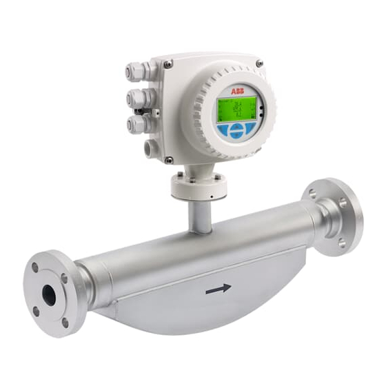
CoriolisMaster FCB400, FCH400
Coriolis mass flowmeter
—
Introduction
CoriolisMaster FCB430 / 450
CoriolisMaster FCH430 / 450
With no up or downstream piping requirements
the compact Coriolis flowmeters can be installed
in the tightest spaces, enabling applications not
possible before.
CoriolisMaster FCB400
The compact Coriolis mass flowmeters from the
CoriolisMaster FCB400 series offer low pressure
drop, high capacity, an intuitive ABB display
featuring a standardized design and cross-
product compatibility, five modular inputs and
outputs as well as HART communication.
CoriolisMaster FCH400
The compact Coriolis mass flowmeters for
hygienic applications from the CoriolisMaster
FCH400 series additionally offer EHEDG certified
cleanability; all wetted materials are polished.
Device firmware version: 01.08.00
Measurement made easy
Additional Information
Additional documentation on CoriolisMaster
FCB400, FCH400 is available for download free of
charge at www.abb.com/flow.
Alternatively simply scan this code:
Advertisement
Table of Contents

Related Manuals for ABB CoriolisMaster FCB400 Series


Summary of Contents for ABB CoriolisMaster FCB400 Series
- Page 1 Alternatively simply scan this code: CoriolisMaster FCB400 The compact Coriolis mass flowmeters from the CoriolisMaster FCB400 series offer low pressure drop, high capacity, an intuitive ABB display featuring a standardized design and cross- product compatibility, five modular inputs and outputs as well as HART communication.
-
Page 2: Table Of Contents
CoriolisMaster FCB400, FCH400 CORIOLIS MASS FLOWMETER | CI/FCB400/FCH400-EN REV. H Table of contents Safety ................4 Storing the device ..............29 General information and instructions ........4 Ambient conditions ............29 Warnings ..................4 Returning devices ..............29 ... - Page 3 Switching on the power supply ........... 73 Parameterization of the device ........... 73 Installation of ABB AssetVision Basic and ABB Field Information Manager (FIM) ..........73 Parameterization via the infrared service port adapter ....................75 ...
-
Page 4: Safety
CoriolisMaster FCB400, FCH400 CORIOLIS MASS FLOWMETER | CI/FCB400/FCH400-EN REV. H 1 Safety Warnings General information and instructions The warnings in these instructions are structured as follows: These instructions are an important part of the product and must be retained for future reference. DANGER Installation, commissioning, and maintenance of the product may only be performed by trained specialist personnel who have... -
Page 5: Intended Use
/ or theft of data or information. the data sheets. ABB Ltd and its affiliates are not liable for damages and / or losses related to such security breaches, any unauthorized When using measuring media, the following points must be... -
Page 6: Use In Potentially Explosive Atmospheres
CoriolisMaster FCB400, FCH400 CORIOLIS MASS FLOWMETER | CI/FCB400/FCH400-EN REV. H 2 Use in potentially explosive atmospheres Note Further information on the Ex-Approval of devices can be found in the type examination certificates or the relevant certificates at www.abb.com/flow Device overview ATEX / IECEx Standard / No explosion protection... -
Page 7: Cfmus
CoriolisMaster FCB400, FCH400 CORIOLIS MASS FLOWMETER | CI/FCB400/FCH400-EN REV. H cFMus Standard / No explosion protection Class I Div. 2 / Zone 2 Class I Div. 1 / Zone 1 (Zone 0) Model number FCx4xx Y0 FCx4xx F2 FCx4xx F1 Integral mount design •... -
Page 8: Ex Marking
CoriolisMaster FCB400, FCH400 CORIOLIS MASS FLOWMETER | CI/FCB400/FCH400-EN REV. H … 2 Use in potentially explosive atmospheres Ex marking Description of model numbers Each device design has a specific model number. The parts of the model number relating to explosion protection are listed in the following table. - Page 9 CoriolisMaster FCB400, FCH400 CORIOLIS MASS FLOWMETER | CI/FCB400/FCH400-EN REV. H Basic model FCa4c Design / transmitter housing / transmitter housing material / cable gland Integral mount / dual-compartment housing / aluminum / 3 × M20 × 1.5 Integral mount / dual-compartment housing / aluminum / 3 × NPT ½ in Integral mount / dual-compartment housing / aluminum / 3 ×...
- Page 10 CoriolisMaster FCB400, FCH400 CORIOLIS MASS FLOWMETER | CI/FCB400/FCH400-EN REV. H … 2 Use in potentially explosive atmospheres … Ex marking Additional ordering information FCa4cdefghijklm Option card 1 2 port Ethernet (various protocols) DR6* 1 × active digital output Option card 2 Power over Ethernet module / Modbus DS8* 1 ×...
-
Page 11: Atex / Iecex
Note • A specific marking applies, depending on the design. • ABB reserves the right to modify the Ex-marking. Refer to the name plate for the exact marking. Model number for use in Zone 2, 21 Ex marking Certificate FCa4c – A2Y0fghijD II3G Ex ec IIC T6...T1 Gc... -
Page 12: Cfmus
Note • A specific marking applies, depending on the design. • ABB reserves the right to modify the Ex-marking. Refer to the name plate for the exact marking. Model number for use in Division 2 Ex marking FCa4c – F2Y0fghijD... -
Page 13: Temperature Data
CoriolisMaster FCB400, FCH400 CORIOLIS MASS FLOWMETER | CI/FCB400/FCH400-EN REV. H Temperature data Temperature resistance for the connecting cable Sensor in remote mount design The temperature at the cable entries of the device depends on the design, the measuring medium temperature T and the medium ambient temperature T... -
Page 14: Measuring Medium Temperature For Sensors In Integral Mount Design With Dual-Compartment Housing
CoriolisMaster FCB400, FCH400 CORIOLIS MASS FLOWMETER | CI/FCB400/FCH400-EN REV. H … 2 Use in potentially explosive atmospheres … Temperature data Measuring medium temperature for sensors in integral mount design with dual-compartment housing Model FCx4xx-A1… and FCx4xx-F1… in Zone 1, Division 1 The table shows the maximum permissible measuring medium temperature as a function of ambient temperature and temperature class. -
Page 15: Measuring Medium Temperature For Sensors In Integral Mount Design With Single-Compartment Housing
CoriolisMaster FCB400, FCH400 CORIOLIS MASS FLOWMETER | CI/FCB400/FCH400-EN REV. H Measuring medium temperature for sensors in integral mount design with single-compartment housing Model FCx4xx-A2… and FCx4xx-F2… in Zone 2, Division 2 The table shows the maximum permissible measuring medium temperature as a function of ambient temperature and temperature class. -
Page 16: Measuring Medium Temperature For Sensors In Remote Mount Design
CoriolisMaster FCB400, FCH400 CORIOLIS MASS FLOWMETER | CI/FCB400/FCH400-EN REV. H … 2 Use in potentially explosive atmospheres … Temperature data Measuring medium temperature for sensors in remote mount design Model FCx4xx-A1…, FCx4xx-F1… in Zone 1 The table shows the maximum permissible measuring medium temperature as a function of ambient temperature and temperature class. -
Page 17: Electrical Data
CoriolisMaster FCB400, FCH400 CORIOLIS MASS FLOWMETER | CI/FCB400/FCH400-EN REV. H Electrical data Overview Standard / No explosion protection Zone 2, 21 Zone 1, 21 (Zone 0) Division 2 and Zone 2, 21 Division 2 and Zone 1, 21 ATEX: ATEX: ATEX: –... -
Page 18: Zone 2, 21 And Division 2 - Model: Fcx4Xx-A2, Fcx4Xx-F2
CoriolisMaster FCB400, FCH400 CORIOLIS MASS FLOWMETER | CI/FCB400/FCH400-EN REV. H … 2 Use in potentially explosive atmospheres … Electrical data Zone 2, 21 and Division 2 – Model: FCx4xx-A2, FCx4xx-F2 Outputs on basic device Operating values (general) Type of protection – ‘nA’ / ‘NI’ Current / HART output 31 / U , active 30 V... - Page 19 CoriolisMaster FCB400, FCH400 CORIOLIS MASS FLOWMETER | CI/FCB400/FCH400-EN REV. H Inputs and outputs with optional plug-in cards Operating values (general) Type of protection – ‘nA’ / ‘NI’ Current output V3 / V4, active* 30 V 30 mA 30 V 30 mA Terminals V3 / V4 and V1 / V2* Current output V1 / V2, passive** 30 V...
-
Page 20: Zone 1 ,21 Und Division 1 - Model: Fcx4Xx-A1, Fcx4Xx-F1
CoriolisMaster FCB400, FCH400 CORIOLIS MASS FLOWMETER | CI/FCB400/FCH400-EN REV. H … 2 Use in potentially explosive atmospheres … Electrical data Zone 1 ,21 und Division 1 – Model: FCx4xx-A1, FCx4xx-F1 Type of protection ‘e’ / ‘XP’ ‘ia’ / ‘IS’ Outputs on basic device [mA] [mA] [mW]... - Page 21 CoriolisMaster FCB400, FCH400 CORIOLIS MASS FLOWMETER | CI/FCB400/FCH400-EN REV. H Type of protection ‘e’ / ‘XP’ ‘ia’ / ‘IS’ Inputs and outputs with optional plug-in cards [mA] [mA] [mW] [mW] [nF] [nF] [nF] [nF] [mH] [mH] Current output V3 / V4, active* 27.8 Terminals V3 / V4 and V1 / V2* Current output V1 / V2, passive**...
-
Page 22: Special Connection Conditions
CoriolisMaster FCB400, FCH400 CORIOLIS MASS FLOWMETER | CI/FCB400/FCH400-EN REV. H … 2 Use in potentially explosive atmospheres … Electrical data Special connection conditions Active digital output DANGER Note Risk of injury caused by live parts! The AS plug-in card (24 V DC loop power supply) may only be Option cards for the active digital output are intended only used to power the internal inputs and outputs on the device. -
Page 23: Installation Instructions
Only original spare parts must be used to seal the housing. Comply with the applicable regulations for the protection of employees to ensure safe operation. Note Spare parts can be ordered from ABB Service. cFMus www.abb.com/contacts The installation, commissioning, maintenance and repair of devices in areas with explosion hazard must only be carried out by appropriately trained personnel. -
Page 24: Cable Entries In Accordance With Atex / Iecex
CoriolisMaster FCB400, FCH400 CORIOLIS MASS FLOWMETER | CI/FCB400/FCH400-EN REV. H … 2 Use in potentially explosive atmospheres … Installation instructions Cable entries in accordance with cFMus Cable entries in accordance with ATEX / IECEx The devices are supplied with cable glands installed (certified in accordance with ATEX or IECEx). -
Page 25: Electrical Connections
18 in (457 mm). The sensor must be grounded in accordance with the applicable international standards. ABB flowmeters are designed for the worldwide industrial Perform grounding of the device in accordance with Terminal market and are suitable for functions such as the measurement assignment on page 47. -
Page 26: Operating Instructions
32-1 must be complied with! Repair Devices of type of protection ‘d’ are equipped with flameproof joints in the housing. Contact ABB before commencing repair work. Changing the type of protection If you are installing in Zone 1 / Div. 1, the current outputs and digital outputs of models FCB430/450 and FCH430/450 can be operated with different types of protection: •... -
Page 27: Product Identification
CoriolisMaster FCB400, FCH400 CORIOLIS MASS FLOWMETER | CI/FCB400/FCH400-EN REV. H 3 Product identification Name plate Note The marking is provided on the name plate and on the sensor The name plates displayed are examples. The device itself in accordance with the Pressure Equipment Directive identification plates affixed to the device can differ from this (PED). -
Page 28: Transport And Storage
CoriolisMaster FCB400, FCH400 CORIOLIS MASS FLOWMETER | CI/FCB400/FCH400-EN REV. H 4 Transport and storage Observe the following instructions: • Do not expose the device to humidity during transport. Pack the device accordingly. • Pack the device so that it is protected against vibrations during transport, for example, by using air-cushioned packing. -
Page 29: Storing The Device
Calculating pressure loss Pressure loss depends on the properties of the medium and the flow rate. A good aid for pressure loss calculation is the Online ABB Product Selection Assistant (PSA) for flow at www.abb.com/flow-selector. -
Page 30: Liquid Measuring Media
CoriolisMaster FCB400, FCH400 CORIOLIS MASS FLOWMETER | CI/FCB400/FCH400-EN REV. H … 5 Installation … General installation conditions Brackets and supports Liquid measuring media No special supports or damping are required for the device when Observe the following points to avoid measuring errors: the device is used and installed as intended. -
Page 31: Gaseous Measuring Media
CoriolisMaster FCB400, FCH400 CORIOLIS MASS FLOWMETER | CI/FCB400/FCH400-EN REV. H For vertical installation in a riser, no special measures are Gaseous measuring media required. Observe the following points to avoid measuring errors: For vertical installation in a downpipe, a piping constriction •... -
Page 32: Turn-Off Devices For The Zero Point Adjustment
CoriolisMaster FCB400, FCH400 CORIOLIS MASS FLOWMETER | CI/FCB400/FCH400-EN REV. H … 5 Installation … General installation conditions Turn-off devices for the zero point adjustment Sensor insulation 1 Insulation Figure 10: Installation at T −50°to 205 °C (−58 to 400 °F) medium The sensor may only be insulated in conjunction with the option TE1 ‘Extended tower length for sensor insulation’... -
Page 33: Devices For Legal Metrology
(with remote mount design) must be sealed. For this purpose, a seal kit is available at ABB. For the assembly of the seal, please observe the separate ‘IN/FCX100/FCX400/MID/OIML-XA’ instructions. -
Page 34: Housing As A Protective Device (Optional)
Material load for process connections Note You can reference the availability of the different process connections in the Online ABB Product Selection Assistant (PSA) for flow www.abb.com/flow-selector. • Not all connections shown here are available in all the devices and designs. -
Page 35: Installing The Sensor
CoriolisMaster FCB400, FCH400 CORIOLIS MASS FLOWMETER | CI/FCB400/FCH400-EN REV. H Installing the sensor Before installation in the piping, observe the installation conditions and instructions on the mounting position! 1. Insert the sensor into the piping centrally and positioned coplanar. Use suitable gaskets to seal the process connections. - Page 36 CoriolisMaster FCB400, FCH400 CORIOLIS MASS FLOWMETER | CI/FCB400/FCH400-EN REV. H … 5 Installation … Installing the transmitter in the remote mount design 1 Hole pattern for mounting holes 2 Female thread (either ½ in NPT or M20 × 1.5), see model coding. In the 1 Hole pattern for mounting holes case of a ½...
-
Page 37: Opening And Closing The Housing
CoriolisMaster FCB400, FCH400 CORIOLIS MASS FLOWMETER | CI/FCB400/FCH400-EN REV. H Opening and closing the housing Dual- compartment housing DANGER Danger of explosion if the device is operated with the transmitter housing or terminal box open! While using the device in potentially explosive atmospheres before opening the transmitter housing or the terminal box, note the following points: •... -
Page 38: Single-Compartment Housing
CoriolisMaster FCB400, FCH400 CORIOLIS MASS FLOWMETER | CI/FCB400/FCH400-EN REV. H … 5 Installation Adjusting the transmitter position … Opening and closing the housing Depending on the installation position, the transmitter housing Single-compartment housing or LCD display can be rotated to enable horizontal readings. Transmitter housing DANGER Damaging the device carries a risk of explosion! - Page 39 CoriolisMaster FCB400, FCH400 CORIOLIS MASS FLOWMETER | CI/FCB400/FCH400-EN REV. H Rotate LCD indicator – dual-compartment housing Rotate LCD indicator – single-compartment housing The LCD indicator can be rotated in three increments of 90° The LCD indicator can be rotated in three increments of 90° each.
-
Page 40: Installing The Plug-In Cards
CoriolisMaster FCB400, FCH400 CORIOLIS MASS FLOWMETER | CI/FCB400/FCH400-EN REV. H … 5 Installation Installing the plug-in cards WARNING Loss of Ex Approval! Loss of Ex Approval due to retrofitting of plug-in cards on devices for use in potentially explosive atmospheres. •... - Page 41 The following table provides an overview of the possible plug-in card combinations that can be selected when ordering the device. Because of the wide variety of options, not all combinations can be presented. Possible combinations are presented in our Online ABB Product Selection Assistant (PSA) for flow at www.abb.com/flow.
-
Page 42: Dual-Compartment Housing
CoriolisMaster FCB400, FCH400 CORIOLIS MASS FLOWMETER | CI/FCB400/FCH400-EN REV. H … 5 Installation … Installing the plug-in cards Dual-compartment housing 1 Cover 4 Slot OC2 2 LCD indicator 5 Slot OC1 3 Frontend board (FEB, with integral mount design only) 6 Plug-in cards Figure 24: Installation of plug-in cards (example, dual-compartment housing) 1. -
Page 43: Single-Compartment Housing
CoriolisMaster FCB400, FCH400 CORIOLIS MASS FLOWMETER | CI/FCB400/FCH400-EN REV. H Single-compartment housing 1 Cover 4 Slot OC2 2 LCD indicator 5 Plug-in cards 3 Slot OC1 Figure 25: Installation of plug-in cards (example, single-compartment housing) WARNING 1. Switch off the power supply. 2.... -
Page 44: Ethernet Card
The electronic components of the printed circuit board can be For detailed instructions how to plug in and connect the Power damaged by static electricity (observe ESD guidelines). over Ethernet (PoE) card, please contact ABB. • Make sure that the static electricity in your body is... -
Page 45: Electrical Connections
CoriolisMaster FCB400, FCH400 CORIOLIS MASS FLOWMETER | CI/FCB400/FCH400-EN REV. H 6 Electrical connections Power supply Safety instructions Note WARNING • Adhere to the limit values of the power supply in accordance Risk of injury due to live parts. with the information on the name plate. Improper work on the electrical connections can result in •... -
Page 46: Installing The Connection Cables
(AWG 19) 200 m (656 ft) Recommended cables It is recommended to use an ABB signal cable for standard applications. The ABB signal cable fulfills the above-mentioned cable specification and can be utilized unrestrictedly up to an ambient temperature of T = 80 °C (176 °F). -
Page 47: Terminal Assignment
CoriolisMaster FCB400, FCH400 CORIOLIS MASS FLOWMETER | CI/FCB400/FCH400-EN REV. H Terminal assignment A Transmitter B Sensor Figure 28: Electrical connection Connections for the power supply Connections for inputs and outputs AC voltage Terminal Function / comments Terminal Function / comments Uco / 32 Current output 4 to 20 mA- / HART®... -
Page 48: Electrical Data For Inputs And Outputs
CoriolisMaster FCB400, FCH400 CORIOLIS MASS FLOWMETER | CI/FCB400/FCH400-EN REV. H … 6 Electrical connections Electrical data for inputs and outputs Current output 32 / Uco, 31 / 32 (basic device) Note Can be configured for outputting mass flow, volume flow, When using the device in potentially explosive atmospheres, density and temperature via on-site software. - Page 49 CoriolisMaster FCB400, FCH400 CORIOLIS MASS FLOWMETER | CI/FCB400/FCH400-EN REV. H In the case of digital communication via Modbus / PROFIBUS DP, Current output Uco / 32 as loop power supply for digital the current output Uco / 32 can be switched to the ‘Power Mode’ output 41 / 42 or 51 / 52 operating mode through the software.
- Page 50 CoriolisMaster FCB400, FCH400 CORIOLIS MASS FLOWMETER | CI/FCB400/FCH400-EN REV. H … 6 Electrical connections … Electrical data for inputs and outputs Digital output 41 / 42, 51 / 52 (basic device) Current output V1 / V2, V3 / V4 (plug-in module) Can be configured as pulse, frequency or binary output via on- Up to two additional plug-in modules can be implemented via site software.
- Page 51 CoriolisMaster FCB400, FCH400 CORIOLIS MASS FLOWMETER | CI/FCB400/FCH400-EN REV. H Passive digital output V1 / V2, V3 / V4 (plug-in card) Active digital output V1 / V2, V3 / V4 (plug-in card) An additional binary output can be implemented via the ‘Passive An additional binary output can be implemented via the ‘Active digital output (green)’...
- Page 52 CoriolisMaster FCB400, FCH400 CORIOLIS MASS FLOWMETER | CI/FCB400/FCH400-EN REV. H … 6 Electrical connections … Electrical data for inputs and outputs Dependency of the output voltage U from the load R Binary output (active) Load R is the parallel connection of the internal resistance R Terminals V1 / V2, V3 / V4 and optional external resistance R...
-
Page 53: Connection Examples
CoriolisMaster FCB400, FCH400 CORIOLIS MASS FLOWMETER | CI/FCB400/FCH400-EN REV. H 24 V DC loop power supply (plug-in module) Connection examples Use of the ‘loop power supply (blue)’ plug-in card allows a Input and output functions are configured via the device passive output on the transmitter to be used as an active software in accordance with the desired application. - Page 54 CoriolisMaster FCB400, FCH400 CORIOLIS MASS FLOWMETER | CI/FCB400/FCH400-EN REV. H … 6 Electrical connections … Electrical data for inputs and outputs Digital output 41 / 42, 51 / 52 passive on distributed control Current output V3 / V4 active system When the ‘loop power supply 24 V DC, blue’...
- Page 55 CoriolisMaster FCB400, FCH400 CORIOLIS MASS FLOWMETER | CI/FCB400/FCH400-EN REV. H Connection versions digital output 41 / 42, 51 / 52 Depending on the wiring of digital outputs DO 41 / 42 and 51 / 52, they can be used parallel or only individually. The electrical isolation between the digital outputs also depends on the wiring.
-
Page 56: Connection To Integral Mount Design
CoriolisMaster FCB400, FCH400 CORIOLIS MASS FLOWMETER | CI/FCB400/FCH400-EN REV. H … 6 Electrical connections Connection to integral mount design Dual- compartment housing Single-compartment housing 1 Terminals for power supply 5 LCD indicator 2 Cover for power supply terminals 6 Bracket for LCD indicator (park position) 3 Terminals for inputs and outputs 7 Terminal for protective earth / cable shields 4 Terminal for potential equalization... - Page 57 CoriolisMaster FCB400, FCH400 CORIOLIS MASS FLOWMETER | CI/FCB400/FCH400-EN REV. H NOTICE If the O-ring gasket is seated incorrectly or damaged, this may have an adverse effect on the housing protection class. Follow the instructions in Opening and closing the housing on page 37 to open and close the housing safely.
-
Page 58: Connection To Remote Mount Design
CoriolisMaster FCB400, FCH400 CORIOLIS MASS FLOWMETER | CI/FCB400/FCH400-EN REV. H … 6 Electrical connections Connection to remote mount design Transmitter Dual- compartment housing A Upper terminal box (back side) 3 Terminals for signal cable B Lower terminal box 4 Terminals for inputs and outputs C Signal cable to sensor 5 Terminal for potential equalization 1 Terminals for power supply... - Page 59 37 to open and close the housing safely. connection area of the transmitter. • Connect the cables in accordance with the electrical Terminal ABB signal cable HELKAMA signal cable connection diagram. If present, connect the cable shielding 3KQZ407123U0100 20522 to the earthing clamp provided.
- Page 60 37 to open and close the housing safely. earthing clamp provided. • Use wire end ferrules when connecting. Terminal ABB signal cable HELKAMA signal cable • From an ambient temperature of T ≥ 60 °C (≥ 140 °F) amb.
-
Page 61: Digital Communication
Using the Modbus protocol allows devices made by different PCS7) on request. manufacturers to exchange information via the same The necessary DTMs and other files can be downloaded from communication bus, without the need for any special interface www.abb.com/flow. devices to be used. HART output Modbus protocol Terminals... -
Page 62: Cable Specification
40 m (131 ft) divided by ‘n.’ www.profibus.com. The maximum cable length depends on the type of cable used. ABB provides three different GSD files which can be integrated in The following standard values apply: the system. -
Page 63: Ethernet/Ip™ Communication
White / Blue at > 1500 kBit/s: LS = 0.00 m! Pin 2 PWR+ Blue • At 1500 kBit/s and ABB DP cable type A: Pin 3 PWR− White / Brown – Sum of all spur cable lengths (L ) ≤ 6.60 m, trunk cable Pin 4 PWR−... -
Page 64: Ethernet Communication
CoriolisMaster FCB400, FCH400 CORIOLIS MASS FLOWMETER | CI/FCB400/FCH400-EN REV. H … 6 Electrical connections … Digital communication Two port connection without power over Ethernet Further Ethernet communication protocols Note Terminal designation: The device supports following security modes: Port Function Color coding Secured Protocols: Pin 1 White / Orange... - Page 65 CoriolisMaster FCB400, FCH400 CORIOLIS MASS FLOWMETER | CI/FCB400/FCH400-EN REV. H Wiring with different network topologies A Daisy-chain C Star B Ring Figure 57: Connection topologies Ethernet Option Cards are designed only for use in hazardous applications Zone 2 / Division 2 or general purpose areas. The output circuits are designed so that different topologies such as daisy chain or point to point can be connected.
-
Page 66: Connect The Retractable Plug To The Ethernet Card
CoriolisMaster FCB400, FCH400 CORIOLIS MASS FLOWMETER | CI/FCB400/FCH400-EN REV. H … 6 Electrical connections … Digital communication Topology No. Ethernet cables No. wires in Port Clamp Function Cable connected Ethernet cable Ring or daisy-chain white / orange RD− orange white / green TD−... - Page 67 CoriolisMaster FCB400, FCH400 CORIOLIS MASS FLOWMETER | CI/FCB400/FCH400-EN REV. H Preparing the EtherNet Cat5e cable M12 plug (option) Various options for M12 plugs are available from the model code: • Flowmeter equipped with 1 × M12 (with 4 wires, connecting to Port 1) •...
- Page 68 CoriolisMaster FCB400, FCH400 CORIOLIS MASS FLOWMETER | CI/FCB400/FCH400-EN REV. H … 6 Electrical connections … Digital communication Use in hazardous areas 1. Remove the metal M12 connector closing cap at transmitter WARNING enclosure from delivery state. 2. Connect the customer M12 connector cable. There are limitations of the M12 plug in combination with a 3.
- Page 69 CoriolisMaster FCB400, FCH400 CORIOLIS MASS FLOWMETER | CI/FCB400/FCH400-EN REV. H Electrical connections For the internal wiring inside the transmitter and the related pinout within the RJ45 connector, refer to table below: Wiring inside the transmitter Color Ethernet card port/pin RJ45 with 4 wires Yellow Port 1 X1 Orange...
- Page 70 CoriolisMaster FCB400, FCH400 CORIOLIS MASS FLOWMETER | CI/FCB400/FCH400-EN REV. H … 6 Electrical connections … Digital communication Ethernet card status LEDs The 6 LEDs on the Ethernet card indicate the status of each port and the network. To enable card status indication in the upper HMI Line, navigate to ‘Display / Display Tag / Ethernet Status’. A Port 1 D Activity 2 B Activity 1...
-
Page 71: Commissioning
CoriolisMaster FCB400, FCH400 CORIOLIS MASS FLOWMETER | CI/FCB400/FCH400-EN REV. H 7 Commissioning Hardware settings Safety instructions DANGER Dual- compartment housing Explosion hazard Improper installation and commissioning of the device carries a risk of explosion. • For use in potentially explosive atmospheres, observe the information in Use in potentially explosive atmospheres on page 6! CAUTION... -
Page 72: Single-Compartment Housing
CoriolisMaster FCB400, FCH400 CORIOLIS MASS FLOWMETER | CI/FCB400/FCH400-EN REV. H … 7 Commissioning … Hardware settings Single-compartment housing Configuration of digital outputs V1 / V2 or V3 / V4 1 DIP switch, Write protection Figure 64: Position of the DIP switch The DIP switches are used to configure specific hardware functions. -
Page 73: Checks Prior To Commissioning
Not all tools and frame applications support DTMs or EDDs at process: the same level. In particular, optional or advanced EDD / DTM functions may not be available on all tools. ABB provides frame System Startup applications supporting the full range of functions and Processing performance. - Page 74 1. Install ABB Field Information Manager (FIM). ‘3KXF410100S0002_DTM_FCXxxx_HART_CoriolisMaster‘. 2. Unpack the ABB FDI package into the c:\temp folder. 5. Connect the flowmeter with the PC / laptop, see chapter 3. Connect the flowmeter with the PC / laptop, see chapter...
-
Page 75: Parameterization Via The Infrared Service Port Adapter
Figure 67: Select FIM – COM-Port adapter. 8. Select the corresponding COM port. Close the menu by By combining the HART-DTM and the software ‘ABB AssetVision’ clicking on “send”. available at www.abb.com/flow, all parameters can also be set 9. By using the menu button on the left side, the without a HART connection. -
Page 76: Parameterization Via Hart
Configuration via the HART interface of the device requires a PC / Notebook and a suited HART® Modem. All parameters can also be set via the HART protocol, using the HART DTM available at www.abb.com/flow and the ABB AssetVision software. 1 PC / Notebook running ABB... -
Page 77: Basic Setup
CoriolisMaster FCB400, FCH400 CORIOLIS MASS FLOWMETER | CI/FCB400/FCH400-EN REV. H Basic Setup The device can be factory parameterized to customer specifications upon request. If no customer information is available, the device is delivered with factory settings. Settings for the most common parameters are summarized in the ‘Easy Setup’ menu. This menu is the quickest way to perform the initial configuration of the device. - Page 78 CoriolisMaster FCB400, FCH400 CORIOLIS MASS FLOWMETER | CI/FCB400/FCH400-EN REV. H … 7 Commissioning … Basic Setup Menu / parameter Description Dig.Out 51 / 52 Mode Selection of the operating mode for the digital output 51 / 52. • Off: Digital output deactivated. •...
- Page 79 CoriolisMaster FCB400, FCH400 CORIOLIS MASS FLOWMETER | CI/FCB400/FCH400-EN REV. H Menu / parameter Description Easy Setup Dig.Out V1 / V2 Mode Selection of the operating mode for digital output V1 / V2. Digital output V1 / V2 is only available if the corresponding plug-in card is present! •...
- Page 80 CoriolisMaster FCB400, FCH400 CORIOLIS MASS FLOWMETER | CI/FCB400/FCH400-EN REV. H … 7 Commissioning … Basic Setup Menu / parameter Description DO 41/42 Freq. Selection of process value issued via the frequency or pulse output. Only if digital output 41 / 42 has been configured as a frequency or pulse output. Dig.Out 41/42 Pulse Dig.Out 51/52 Freq.
-
Page 81: Operation
CoriolisMaster FCB400, FCH400 CORIOLIS MASS FLOWMETER | CI/FCB400/FCH400-EN REV. H 8 Operation Safety instructions CAUTION The LCD indicator has capacitive operating buttons. These enable you to control the device through the closed housing Risk of burns due to hot measuring media cover. -
Page 82: Menu Levels
CoriolisMaster FCB400, FCH400 CORIOLIS MASS FLOWMETER | CI/FCB400/FCH400-EN REV. H … 8 Operation Menu levels Process display Information level Configuration level (Operator Menu) (Configuration) ...Operator Page 1 … 4 Easy Setup Autoscroll Device Info Diagnostics Device Setup Signals View Display Input/Output Process Alarm Communication... -
Page 83: Selecting And Changing Parameters
CoriolisMaster FCB400, FCH400 CORIOLIS MASS FLOWMETER | CI/FCB400/FCH400-EN REV. H Selecting and changing parameters Entry from table Parameter name When an entry is made from a table, a value is selected from a 12.3456 [unit] list of parameter values. Menu name Next Parameter name Currently set value... -
Page 84: Error Messages On The Lcd Display
CoriolisMaster FCB400, FCH400 CORIOLIS MASS FLOWMETER | CI/FCB400/FCH400-EN REV. H … 8 Operation Error messages on the LCD display … Selecting and changing parameters In the event of an error, a message consisting of a symbol and Exiting the setup text (e.g. -
Page 85: Maintenance / Repair
• Devices for use in potentially explosive atmospheres may give rise to hazards when dismantling the device. be serviced and repaired by qualified ABB personnel only. • If necessary, wear suited personal protective equipment •... -
Page 86: Disposal
… 10 Dismounting and disposal 11 Specification Disposal Note The device data sheet is available in the ABB download area at Note www.abb.com/flow. Products that are marked with the adjacent symbol may not be disposed of as unsorted municipal waste (domestic waste). -
Page 87: Appendix
CoriolisMaster FCB400, FCH400 CORIOLIS MASS FLOWMETER | CI/FCB400/FCH400-EN REV. H 13 Appendix Return form Statement on the contamination of devices and components Repair and/or maintenance work will only be performed on devices and components if a statement form has been completed and submitted. - Page 88 We reserve the right to make technical changes or modify the contents of this document without prior notice. With regard to purchase orders, the agreed particulars shall prevail. ABB does not accept any responsibility whatsoever for potential errors or possible lack of information in this document.