Summary of Contents for ABB FCB400 Series
- Page 1 — A BB MEA SU RE ME NT & A NA LYTI CS | 2 1 087 4 4 MNA A HSPC Module Configuration Guide Connection to CoriolisMaster FCB400/FCH400 Series...
-
Page 2: Table Of Contents
Additional free publications are available for download at www.abb.com/upstream or by scanning a code: Coriolis Product Page CoriolisMaster FCH400 Series CoriolisMaster FCB400 Series Table 0-1: Related documentation Documents Document number/ID TFIO HSPC Module Data Sheet 2108710 TFIO Module User Manual... -
Page 3: Overview
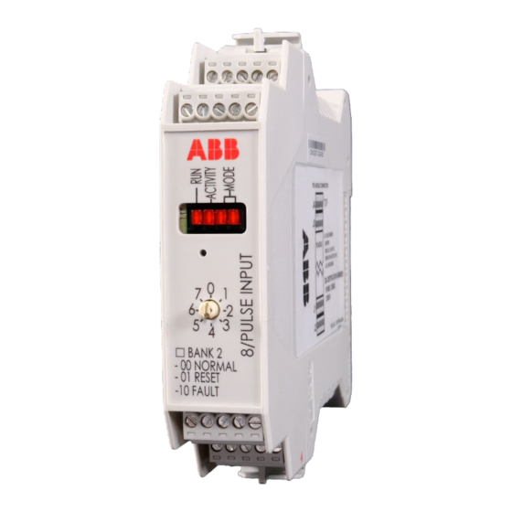
Overview This guide provides instructions to configure the ABB High Speed Pulse Counter (HSPC) TFIO module for connection with the ABB CoriolisMaster FCB400 or FCH400 series of Coriolis mass flowmeters. An HSPC module I/O point is configured as a Pulse Input (PI). This Input connects to one of the CoriolisMaster’s Digital Outputs (Digital Output 41/42). -
Page 4: Wire The Hspc Module Power (If Required)
Take note of the terminal connector point. This point is configured from the interface. The (J1- 1, J1-2) point is identified as DI1 in PCCU. Tighten connector screws to secure wires. Set module address if not using the default. a. Insert the small flathead screwdriver in the address selector slot. b. - Page 5 I/O channel configuration Input configuration Power Mode (if applicable) configuration Mix of channels configured Inputs may be configured with Wetting Use External as Pulse inputs or Digital Outputs Current/Pullup disabled or enabled. Equipment (if an external power is required for the HSPC module): A power supply with an operating rating of 30 VDC, 5 A (maximum).
-
Page 6: Wire The Coriolismaster Digital Output
Verify correct polarity in all terminal connector wiring. Reinsert terminal connectors on module. Wire the (non-energized) power supply terminals, ensuring correct polarity. Refer to the power supply documentation for details. Wire the CoriolisMaster digital output This procedure shows how to wire one of the CoriolisMaster digital outputs to the HSPC module. This procedure wires Digital Output 1 (pins 41, 42). -
Page 7: Configure The Hspc Input
– HSPC terminal connectors are inserted in the module and the module is installed. – The CoriolisMaster is wired for power. Refer to the CoriolisMaster Operating Instructions for details (See Additional information for a link to the document). To apply power: Connect the HSPC module to the flow computer or remote controller TFIO or I2C Bus interface. -
Page 8: Verify Output From Coriolismaster
Figure 6-2: Configure Digital I/O 1 as a Digital Input 12. Click Send. 13. On the PCCU navigation tree, expand TFIO 8/HSPC I:00. Then select Advanced. 14. Select the Pulse Input tab. 15. Under the Wetting Current/Pullup Enable section, select the value field next to the point. In this example, the point is identified as DI1. -
Page 9: Verify Input Detection At The Hspc Module
DO 41/42 frequency output of 1000 Hz. Figure 7-2: ABB CoriolisMaster DO 41/42 frequency output Verify input detection at the HSPC module This procedure verifies that the HSPC module receives pulse inputs from the CoriolisMaster. - Page 10 Figure 8-1: Detection of Pulse Inputs 1 0 | HS PC CO N FI G U RATI ON G UI D E | 21 08 7 44M N A A...
- Page 11 We reserve the right to make technical changes or modify the contents of this document without prior notice. With regard to purchase orders, the agreed particulars shall prevail. ABB does not accept any responsibility whatsoever for potential errors or possible lack of information in this document. We reserve all rights in this document and in the subject matter and illustrations contained therein.


