
Related Manuals for Toro SnowMaster


Summary of Contents for Toro SnowMaster
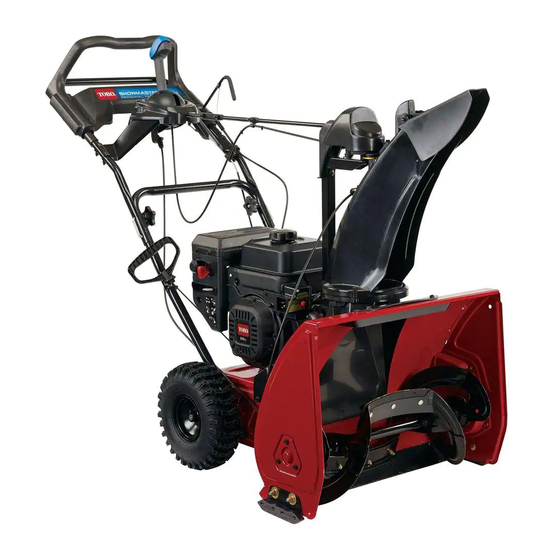
- Page 1 R e s i d e n t i a l P r o d u c t s S n o w Ma s t e r ® / S n o w Ma x ® I s s u e d : Ma y 2 0 1 6...
-
Page 2: About This Manual
Basic shop safety knowledge and mechanical/electrical skills are assumed. The Table of Contents lists the systems and the related topics covered in this manual. The SnowMaster® and SnowMax® Snowthrower is covered in this manual. The manual may also be specified for use on later model products. - Page 3 3-18 Jackshaft Removal and Replacement..................... 3-19 Transmission Replacement........................3-22 Main Frame Diagram..........................3-24 Scraper Removal and Replacement......................3-25 Paddle Removal and Replacement......................3-25 Quickstick Diagram........................... 3-26 Clocking the Quick Stick........................... 3-27 Toro® - SnowMaster® Service Manual TOC1 Table of Contents...
-
Page 4: General Information
SAFETY INFORMATION General Information provided herein are for troubleshooting, ser- This symbol means WARNING or vice, and repair of the Toro SnowMaster ® PERSONAL SAFETY INSTRUC- SnowMax snowthrowers. The SnowMaster ® TION - read the instruction operator’s manuals contain safety information... -
Page 5: Torque Specifications
Fastener Identification Recommended fastener torque values are listed in the following tables. For critical applications, as determined by Toro, either the recommended torque or a torque that is unique to the application is clearly identified and specified in the service manual. -
Page 6: Specifications And Maintenance
The tolerance is approximately ± 10% of fasteners into threaded aluminum or the nominal torque value. Thin height nuts brass. The specific torque value should be include jam nuts. Toro® - SnowMaster® Service Manual Table of Contents... -
Page 7: Other Torque Specifications
Newton-Meters 1.356 Work Foot-pounds Kilogram-Meters 0.1383 Inch-pounds Kilogram-Centimeters 1.152144 Quarts Liters 0.9463 Liquid Volume Gallons Liters 3.785 Liquid Flows Gallons/Minute Liters/Minute 3.785 1. Subtract 32° Temperature Fahrenheit Celsius 2. Multiply by 5/9 Toro® - SnowMaster® Service Manual Table of Contents... -
Page 8: Equivalents And Conversions
23.812 29/64 0.453125 11.509 61/64 0.953125 24.209 15/32 0.46875 11.906 31/32 0.96875 24.606 31/64 0.484375 12.303 63/64 0.984375 25.003 0.5000 12.700 1.000 25.400 1 mm = 0.03937 in. 0.001 in. = 0.0254mm Toro® - SnowMaster® Service Manual Table of Contents... -
Page 9: Recommended Maintenance Schedule(S)
Maintain or replace safety and instruction labels, as necessary. • Do not change the governor settings on the engine. • Purchase only genuine Toro replacement parts and accessories. Checking the Engine Oil Level Service Interval: Before each use or daily Figure 1 Remove the dipstick, wipe it clean, then fully insert Low oil level—add oil... -
Page 10: Checking And Adjusting The Skids
2. Place an oil drain pan under the oil-drain plug, remove the oil-drain plug, and tip the machine backward and drain the used oil in the oil-drain pan (Figure 4). Figure 2 1. 5 mm (3/16 inch) board 2. Ground Toro® - SnowMaster® Service Manual Table of Contents... - Page 11 36003, 38712 0.7 L (23.7 oz) Oil type: automotive detergent oil with an API service classification of SJ, SL, or higher. Figure 5 Figure 6 Low oil level—add oil Correct oil level Toro® - SnowMaster® Service Manual Table of Contents...
-
Page 12: Replacing The Spark Plug
Loosen the nut on the lower cable clamp, but do not Wait until the engine is cool to replace the spark plug. remove it (Figure 9). Use a Toro spark plug or equivalent (Champion® RN9YC or NGK BPR6ES). Remove the boot (Figure 7). -
Page 13: Adjusting The Transmission Cable
3. Tighten the nut (Figure 10). Checking the Tire Pressure Service Interval: Yearly Set the tire pressure equally in both tires to between 103 and 137 kPa (15 and 20 psi). Toro® - SnowMaster® Service Manual Table of Contents... -
Page 14: Storing The Snowthrower
Authorized Service Dealer. Sand affected areas before painting, and use a rust preventative to prevent the metal parts from rusting. 15. Tighten any loose fasteners. Repair or replace any damaged parts. Toro® - SnowMaster® Service Manual 2-10 Table of Contents... - Page 15 Rotor cable is to be adjusted so 1.00 ± .05 in. of conduit sticks out past cable anchor. Ensure there is slack in cable after adjustment to ensure brake still functions. Toro® - SnowMaster® Service Manual Table of Contents...
- Page 16 Torque engine pulley bolt to 170 ± 15 in-lbs. (19.5 ± before installing engine pulley. 1.7 Nm) When inspecting the proper torque, torque must be checked immediately before Loctite® 243 sets Apply Loctite® 243 to the threads of the engine mounting studs. Toro® - SnowMaster® Service Manual Table of Contents...
- Page 17 8. Spring Cover 3. Chute Support Tube Bracket 9. Extension Spring 10. LH Upper Shroud 4. Chute Post 5. Chute Gear 11. RH Lower Shroud 6. Chute 12. Housing Kicker 13. Chute Ring Toro® - SnowMaster® Service Manual Table of Contents...
- Page 18 2. Chute Guide 8. Face Gear 9. Gear Chute Cover 3. Chute Post 4. Chute Gear 10. LH Upper Shroud 5. Chute 11. RH Lower Shroud 6. Chute Ring 12. Housing Kicker Toro® - SnowMaster® Service Manual Table of Contents...
- Page 19 Figure 15 Figure 17 5. Remove the lower chute (item 1) from the unit. 3. Install the RH (item 11) and LH (item 10) upper shrouds. Torque screws to 25-35 in-lbs. (2.8-4 Nm). Toro® - SnowMaster® Service Manual Table of Contents...
-
Page 20: Belt Removal & Replacement
4. Work the belt off the jackshaft pulley, remove rotor (7-9 Nm). pulley and belt. NOTE: Match the orientation of rotor pulley with the above image to prevent putting rotor pulley on backwards. Toro® - SnowMaster® Service Manual Table of Contents... - Page 21 Rotor cannot make contact with frame or ground surface. Torque to 40-60 in-lbs. (4-7 Nm) Paddles, item B, should be assembled with wear indicator holes in positions shown, when viewed from front. Toro® - SnowMaster® Service Manual Table of Contents...
- Page 22 3. On the opposite side, remove the three bolts on the Nm). bearing cap. 4. Remove the bearing bolt. Remove the bearing and bearing retainer, rubber washer, and thrust washer. Figure 26 Figure 24 5. Slide the rotor one way and remove. Toro® - SnowMaster® Service Manual Table of Contents...
-
Page 23: Rotor Removal & Replacement
(4.6-7 Nm). 4. Install the bolts that go behind the rotor pulley. Torque to 60-80 in-lbs. (7-9 Nm). 5. Install the rotor belt and belt cover as outlined in “Belt Removal & Replacement.” Toro® - SnowMaster® Service Manual Table of Contents... - Page 24 Install transmission bearing support after idler arm and hole in jackshaft support plate. jackshaft assembly is tightened to left hand side plate. Insure pulley and shaft rotate freely after assembled. Toro® - SnowMaster® Service Manual 3-10 Table of Contents...
- Page 25 2. Remove the cable end from its retainer (Figure 28). Figure 30 5. Remove cable from the spring. Figure 28 3. Remove the bolt from inside the belt cover (Figure 29). Figure 29 Toro® - SnowMaster® Service Manual 3-11 Table of Contents...
- Page 26 Torque bolts to 60-80 in-lbs. (7-9 Nm) (Figure 32). Figure 34 5. Install the LH upper shroud and belt cover. Torque shroud bolts to 25-35 in-lbs. (2.8-4 Nm). Torque cover bolts to 60-80 in.-lbs. (7-9 Nm). Figure 32 Toro® - SnowMaster® Service Manual 3-12 Table of Contents...
-
Page 27: Transmission Removal
2. Tip blower forward resting the auger housing on a 38). protective mat. Remove the fasteners holding the lower belt cover in place. Remove the cover (Figure 36). Figure 38 Figure 36 7. Slide the belt out. Toro® - SnowMaster® Service Manual 3-13 Table of Contents... - Page 28 Figure 39 9. Slide the transmission to the right until the left hand axle clears the housing. Lift the transmission up and out. Disconnect the traction cable (Figure 40). Figure 40 Toro® - SnowMaster® Service Manual 3-14 Table of Contents...
-
Page 29: Pulley Removal
Figure 43 4. Using a puller, pull the bearing off the shaft. Remove the pulley. Figure 41 2. Using a punch, tap the pin out of the pulley. Figure 44 Figure 42 Toro® - SnowMaster® Service Manual 3-15 Table of Contents... - Page 30 2. Tap the pulley into position Figure 48 5. Insert the transmission into a vice or clamp to create a solid surface for the pulley to rest on. Figure 46 Figure 49 Toro® - SnowMaster® Service Manual 3-16 Table of Contents...
- Page 31 Figure 52 9. Pulley and bearing installation is complete. Figure 50 7. Remove the pinch punch. Insert the new pin. Figure 53 Figure 51 Toro® - SnowMaster® Service Manual 3-17 Table of Contents...
- Page 32 6. Extension Spring Lubricate idler arm, on both sides around pivot hole with grease. Spring must be assembled as shown, it must pass through both the slot and hole in spring clip. Toro® - SnowMaster® Service Manual 3-18 Table of Contents...
- Page 33 (item 4). Remove the pulley (Figure 56). Figure 58 6. Remove the three bearing retainer bolts form the side of the housing. Remove the bearing retainer (Figure 59). Figure 56 Figure 59 Toro® - SnowMaster® Service Manual 3-19 Table of Contents...
- Page 34 8. Slide the jackshaft support plate to the right and 2. Slide the jackshaft support plate, thrust washer, remove (Figure 61). bearing, and bearing retainer onto the jackshaft inside the housing (Figure 63). Figure 61 Figure 63 Toro® - SnowMaster® Service Manual 3-20 Table of Contents...
- Page 35 6. Install the other jackshaft pulley. Torque to 96 in-lbs. (11 Nm). Install the lower bearing retainer. Torque to 96 in-lbs. (11 Nm) (Figure 65). Figure 65 3. Install the mounting bolts. Torque to 96 in-lbs. (11 Nm). Toro® - SnowMaster® Service Manual 3-21 Table of Contents...
- Page 36 (Figure 68). Figure 70 5. Route the belt the correct way and install belt on crankshaft pulley (Figure 71). Figure 68 Figure 71 Toro® - SnowMaster® Service Manual 3-22 Table of Contents...
- Page 37 (Figure 72). Figure 72 7. Install the belt covers and install all mounting bolts. 8. Install the wheels. Add anti-seize to lock wheels. 9. Replace all shrouds, the drive belt and cover. Toro® - SnowMaster® Service Manual 3-23 Table of Contents...
- Page 38 Place a 0.2 in. thick spacer under scraper. Position the skid so it is resting on the ground, tighten fasteners while holding skid to prevent from rotating. Toro® - SnowMaster® Service Manual 3-24 Table of Contents...
- Page 39 Install the new paddles, tighten the center bolt first. 1. Install the new scraper and torque bolts to 96 in-lbs. Torque bolts to 45-55 in-lbs. (5.2-6.3 Nm) (Figure (11 Nm) 76). Refer to page 2-6, Figure 3. Figure 76 Toro® - SnowMaster® Service Manual 3-25 Table of Contents...
- Page 40 1. Latch Trigger 2. LH Chute Lever Cover 3. Chute Control Rod 4. Lever Cap 5. RH Chute Control Lever 6. LH Chute Control Lever 7. RH Chute Lever Cover 8. Chute Rod Toro® - SnowMaster® Service Manual 3-26 Table of Contents...
- Page 41 3. Loosen the two screws holding the chute gear mount to the Quick Stick chute post (Figure 79). 7. Install the top cover. Torque bolts to 6-10 in-lbs. (7- 1.1 Nm). Figure 79 Toro® - SnowMaster® Service Manual 3-27 Table of Contents...
- Page 42 R e s i d e n t i a l P r o d u c t s 2 0 1 6 T h e T o r o C o mp a n y . A l l r i g h t s r e s e r v e d .