Table of Contents
Advertisement
Advertisement
Table of Contents

Related Manuals for Xterra TRX4500


Summary of Contents for Xterra TRX4500
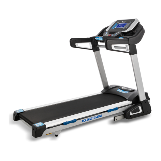
- Page 1 TRX4500 TREADMILL...
-
Page 2: Table Of Contents
TABLE OF CONTENTS Important Safety Instructions Important Electrical Information Important Operation Instructions Assembly Pack Checklist Assembly instructions Folding Instructions Operation of Your Treadmill General Maintenance Exploded View Diagram Parts List GT90D-NT024CEGS_1804A(XL) -
Page 3: Important Safety Instructions
Important Safety Instructions WARNING - Read all instructions before using this appliance. DANGER - To reduce the risk of electric shock disconnect your treadmill from the electrical outlet prior to cleaning and/or service work. WARNING - To reduce the risk of burns, fire, electric shock, or injury to persons, install the treadmill on a flat level surface with access to a 220-volt AC, 10-amp grounded outlet. -
Page 4: Important Electrical Information
Important Electrical Information WARNING! NEVER use a ground fault circuit interrupt (GFCI) wall outlet with this treadmill. As with any appliance with a large motor, the GFCI will trip often. Route the power cord away from any moving part of the treadmill including the elevation mechanism and transport wheels. NEVER remove any cover without first disconnecting AC power. -
Page 5: Important Operation Instructions
Important Operation Instructions NEVER operate this treadmill without reading and completely understanding the results of ● any operational change you request from the computer. Understand that changes in speed and incline do not occur immediately. Set your desired ● speed on the computer console and release the adjustment key. The computer will obey the command gradually. -
Page 6: Assembly Pack Checklist
ASSEMBLY PACK CHECKLIST # 74. 3.5 × 12m/m # 80. Ø8 × 1.5T 99. 5/16" ×1/2" Sheet Metal Screw (4pcs) Split Washer (4pcs) Hex Head Bolt (8pcs) # 126. M5 ×15L # 125. 5/16" ×3/4" # 100. Ø5/16" × Ø18 × 1.5T Phillips Head Screw (6pcs) Button Head Socket Bolt (8pcs) Flat Washer (8pcs) -
Page 7: Assembly Instructions
ASSEMBLY INSTRUCTIONS STEP 1 Take out the treadmill from the carton and lay it aside on the smooth ground. STEP 2 Connect Computer Cable (Middle) (54) with Computer Cable (Lower) (55) then insert Right and Left Uprights (4) and (5) into the Frame Base (2) and use 13m/m Wrench (90) to tighten 8 pcs of 5/16"... - Page 8 STEP 3 Connect the Computer Cable (Middle) (54) and Computer Cable (Upper) (53). Connect the Speed Adjustment Switch W/Cable (Upper) (114) and Speed/Hand Pulse Complex (28). Connect the Incline Adjustment Switch W/Cable (Upper) (115) and Incline/Hand Pulse Complex (29). Insert Console Assembly (21) into right and left Uprights (4) and (5) and secure with 4 pcs of 5/16"...
- Page 9 STEP 5 Install the Front Inner Handlebar Cover (L,R)) (107,110) and Right and Left Uprights with the 4pcs of 3.5 × 12m/m_Sheet Metal Screws (74) by by using Combination M5 Allen Wrench & Phillips Head Screw Driver (102) and tighten them. STEP 6 Use Combination M5 Allen Wrench &...
-
Page 10: Folding Instructions
Folding Instructions Do not attempt to move the unit unless it is in the folded and locked position. Be sure the power cord is secured to avoid possible damage. Use both handrails to maneuver the unit to the desired position. ■... -
Page 11: Operation Of Your Treadmill
Operation of Your Treadmill Power Up Power the treadmill on by plugging it into an appropriate wall outlet, then turn on the power switch located at the front of the treadmill below the motor hood. Ensure that the Safety Key is installed, as the treadmill will not power on without it. - Page 12 Functions Pause / Stop / Reset 1. When the treadmill is running, the pause feature may be utilized by pressing the Start/Stop key once. This will slowly decelerate the tread-belt to a stop. The incline will go to zero percent. The Time, Distance and Calorie readings will also stop.
- Page 13 Program Operation Manual Program 1. Select Manual Program via the Program key then press Enter. The display will prompt you through the programming or you can just press Start to begin the program with default values. The Message window will now be blinking an Age value. Adjust the age and press Enter. The Message window will now be displaying a Weight value.
- Page 14 HRC (Heart Rate Control) 1. Select HRC via the Program key then press Enter. 2. The console displays ”Adjust age, Age> 35”. Press ENTER after age has been adjusted. 3. The console displays ”Adjust weight. Weight> 150”. Press ENTER after weight has been adjusted. 4.
- Page 15 Speed Incline Speed Incline Speed Incline Speed Incline Speed Incline Speed Incline Speed Incline Speed Incline Speed Incline Speed Incline Speed Incline Speed Incline Speed Incline Speed Incline...
- Page 16 HEART RATE PROGRAMS Before we get started, a word about Heart Rate: The old motto, “no pain, no gain”, is a myth that has been overpowered by the benefits of exercising comfortably. A great deal of this success has been promoted by the use of heart rate monitors.
- Page 17 RATE OF PERCEIVED EXERTION Heart rate is important but listening to your body also has a lot of advantages. There are more variables involved in how hard you should workout than just heart rate. Your stress level, physical health, emotional health, temperature, humidity, the time of day, the last time you ate and what you ate, all contribute to the intensity at which you should workout.
-
Page 18: General Maintenance
GENERAL MAINTENANCE BELT & DECK Your treadmill uses a very high-efficient low-friction deck. Performance is maximized when the deck is kept as clean as possible. Use a soft, damp cloth, or paper towel, wipe the edge of the belt and the area between the belt edge and the frame. Also reach as far as practical directly under the belt edge. - Page 19 TREAD-BELT TRACKING ADJUSTMENT The treadmill is designed so that the tread-belt remains reasonably centered while in use. It is normal for some belts to drift near one side while in use, depending on a user’s gait and if they favor one leg. But if during use the belt continues to move toward one side, adjustments are necessary. SETTING TREAD-BELT TRACKING A 6 mm Allen wrench (132)is provided for this adjustment.
- Page 20 BELT/DECK LUBRICATION PROCEDURE First, you want to clean between the belt and deck to remove any debris that may be trapped. Use a clean, non-fraying rag, t-shirt, or light towel. Halfway between the end of the treadmill and motor cover, shove the garment under the belt until you can grasp it on both sides of the belt.
- Page 21 Error Messages Safety Key is not in place. A reminder to put in the safety key. Treadmill calibration did not receive a speed signal for 10 seconds. Over the rated current. The controller is over the rated current for 3 seconds. ERR Incline Error.
-
Page 22: Exploded View Diagram
EXPLODED VIEW DIAGRAM... -
Page 23: Parts List
PARTS LIST Part Number Part Description Qty per unit Main Frame Frame Base Incline Bracket Right Upright Left Upright Console Support Outer Slide Inner Slide Handrail Support Incline Motor Drive Belt Motor Bracket Drive Motor Running Belt Running Deck Front Roller W/Pulley Rear Roller Deck Cross Brace Console Assembly... - Page 24 Part Number Part Description Qty per unit 21~31 Ø32_Console Bracket Anchor 21~32 600m/m_Fan Assembly 21~33 250m/m_Safety Switch Wire 21~34 Receiver, HR 21~35 100m/m_Receiver Connecting Cable Metal Tube End Cap Motor Top Cover Adjustment Base (L) Adjustment Base (R) Speed/Hand Pulse Complex Incline/Hand Pulse Complex Breaker On/Off Switch...
- Page 25 Part Number Part Description Qty per unit 5/16" × 1/2"_Button Head Socket Bolt 5 × 16m/m_Tapping Screw 3.5 × 12m/m_Sheet Metal Screw 1/2" × 8T_Nyloc Nut 3/8" × 7T_Nyloc Nut 5/16" × 7T_Nyloc Nut M8 × 7T_Nyloc Nut Ø10 × 2.0T_Split Washer Ø8 ×...
- Page 26 Part Number Part Description Qty per unit M10 × 8T_Nyloc Nut M5 × 10m/m_Phillips Head Screw Wire Clamp 4 × 25m/m_Sheet Metal Screw Foot Rail Back Plate Chest Strap (Optional) 400m/m_Audio Cable Controller Back Plate 3 × 8m/m_Sheet Metal Screw Link Link Shaft Shaft Bushing...
Need help?
Do you have a question about the TRX4500 and is the answer not in the manual?
Questions and answers