Table of Contents
Advertisement
Quick Links
Advertisement
Table of Contents

Related Manuals for Freescale Semiconductor PE Micro Cyclone Pro


Summary of Contents for Freescale Semiconductor PE Micro Cyclone Pro
- Page 2 MS-DOS & Windows are registered trademarks of Microsoft Corporation. IBM is a registered trademark of IBM corporation. Freescale™ and the Freescale logo are trademarks of Freescale Semiconductor, Inc. All other product or service names are the property of their respective owners.
-
Page 3: Table Of Contents
CYCLONE PRO INTRODUCTION .................... 1 QUICK START GUIDE FOR SAP OPERATION ..........5 CYCLONE PRO HARDWARE................ 8 Cyclone PRO Power Supply ................8 RS232 Communication .................. 8 Ethernet Communication................9 USB Communications ..................9 Electromechanical Relays ................10 Power Connectors..................11 Jumper Settings ................... - Page 4 CYCLONE PRO P&E Microcomputer Systems Software ............58 Freescale Software ..................61 HC08 P&E Multilink/Cyclone PRO Connections...........65 HCS08 P&E Multilink/Cyclone PRO Connections ........84 ETHERNET CONFIGURATION ..............92 Network Architectures...................92 Network Parameters ..................93 Internet Protocol ...................94 Connecting The Cyclone Device ..............94 Cyclone IP Setup Via LCD Menu..............96 Cyclone IP Setup Utility User Interface (ConfigureIP) ........96 Using ConfigureIP.exe To Configure The Cyclone PRO ......98 SERIAL PORT CONFIGURATION .............
- Page 5 CYCLONE PRO 13.11 68HC908GT ....................120 13.12 68HC908GZ ....................121 13.13 68HC908JB1/8 ................... 122 13.14 68HC908JB12 .................... 123 13.15 68HC908JB16 .................... 124 13.16 68HC908JG....................125 13.17 68HC908JK ....................126 13.18 68HC908JL ....................127 13.19 68HC908JR....................128 13.20 68HC908JW ....................128 13.21 68HC908KX ....................
- Page 6 CYCLONE PRO 14.4 SAP Operation Errors .................146 14.5 SAP Blank Check Range and Module Errors ..........146 14.6 SAP Erase Range and Module Errors ............146 14.7 SAP Program Byte, Word, and Module Errors..........146 14.8 SAP Verify Checksum Errors..............147 14.9 SAP Verify Range and Module Errors ............147 14.10 SAP User Function Errors ................147 14.11...
-
Page 7: Introduction
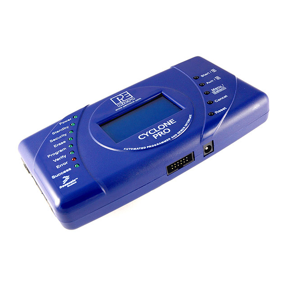
CYCLONE PRO INTRODUCTION The Cyclone PRO is both a powerful production programmer and a versatile development/debugging tool for Freescale microcontroller-based hardware architectures. The Cyclone PRO is designed to withstand the demands of a production environment. It is a Stand-Alone Programmer (SAP) that can be operated manually or used to host automated programming. - Page 8 CYCLONE PRO • Powerful LCD Menu • Executes SAP operations • Selects SAP image • Configures Cyclone PRO IP settings • Displays operation status • Convenient LED Display • Shows programming status during operation • Indicates success or specifies source of failure •...
- Page 9 CYCLONE PRO • Multiple Frequency Operation • Automatically detects and caters to target bus frequencies or BDM frequencies ranging from 1MHz to 8MHz (MON08) or 16KHz to 50MHz (BDM). • Provides a 9.8304 MHz or 4.1952 MHz oscillator signal to overdrive target crystal and RC clock circuitry (MON08).
- Page 10 CYCLONE PRO • Versatile Debugging and Programming Software • Free image creation utility, image management utility, and IP configuration utility • Includes free debugger and programmer for HC908 targets • Includes free programmer for ColdFire V1, HC9S08, RS08, and HC(S)12(X) targets •...
-
Page 11: Quick Start Guide For Sap Operation
CYCLONE PRO QUICK START GUIDE FOR SAP OPERATION Stand-Alone Programming (SAP) is the most common use of the Cyclone PRO. This quick start guide illustrates how easy it is to begin using the Cyclone for stand-alone programming. You are encouraged to read this manual in its entirety for a complete description of all Cyclone PRO features, many of which are beyond the scope of this quick-start guide. - Page 12 CYCLONE PRO devices. Follow these steps to create a SAP image: a. Run the Cyclone Image Creation Utility This utility is a GUI designed to help users create architecture- specific SAP images. To run this utility: From the “Start” menu of your PC, navigate to “All Programs” -> “P&E Cyclone PRO Programmer”...
- Page 13 CYCLONE PRO b. In the Cyclone Image Creation Utility, select your architecture from the “Specify Target Architecture” drop-down list c. Click the “Launch Script Wizard” button. Follow the pop-up screens to specify a programming algorithm and target object file. The program- ming algorithm, target object file, and default programming sequence will then show up in the programming sequence listbox.
-
Page 14: Cyclone Pro Hardware
CYCLONE PRO CYCLONE PRO HARDWARE The following is an overview of the features and interfaces of the Cyclone PRO unit. Cyclone PRO Power Supply The Cyclone PRO requires a regulated 6V DC Center Positive power supply with 2.5/5.5mm female plug. The Cyclone PRO derives its power from the Power Jack located on the side of the unit. -
Page 15: Ethernet Communication
CYCLONE PRO Figure 3-3: Cyclone PRO RS232 Connector Ethernet Communication The Cyclone PRO provides a standard RJ45 socket to communicate with a host computer through the Ethernet Port (10/100 BaseT). Figure 3-4: Cyclone PRO Ethernet Connector USB Communications The Cyclone PRO provides a USB connector for Universal Serial Bus communications between the Cyclone PRO and the host computer. -
Page 16: Electromechanical Relays
CYCLONE PRO Figure 3-5: Cyclone PRO USB Connector Electromechanical Relays Inside the Cyclone PRO, two electromechanical relays are used to cycle target power. The specifications of the relays are as following: Maximum switched power: 30W or 125 VA Maximum switched current: 1A Maximum switched voltage: 150VDC or 300VAC UL Rating: 1A at 30 VDC 1A at 125 VAC... -
Page 17: Power Connectors
CYCLONE PRO Power Connectors The Cyclone PRO provides a Target Power Supply Input Jack and a Target Power Supply Output Jack with 2.5/5.5 mm Pin Diameter. The power jacks are connected or disconnected by two electromechanical relays. When connected, the Center Pin of the Target Power Supply Input Jack is connected to the Center Pin of the Target Power Supply Output Jack. -
Page 18: Optional Oscillator (Mon08 Only)
CYCLONE PRO Optional Oscillator (MON08 Only) The Cyclone PRO provides a software configurable 9.8304MHz or 4.1952 MHz oscillator clock signal to Pin 13 of the MON08 Connector. The user may use this clock signal to overdrive the target RC or crystal circuitry. If this signal is not used, just leave Pin 13 of the target MON08 header unconnected. -
Page 19: Target Mon08 Connector
CYCLONE PRO 3.10 Target MON08 Connector The Cyclone PRO provides a standard 16-position 0.100-inch pitch dual row 0.025-inch square header for the HC08 targets. The mechanical drawing is shown below. Figure 3-8: 16-Pin Header Mechanical Drawing Cyclone PRO User Manual... - Page 20 CYCLONE PRO The MON08 Connector adopts the standard pin-out from MON08 debugging (as used on different ICS boards) with some modifications. The general pin- out is as follows: PIN 1 - - PIN 2 PIN 3 - - PIN 4 PIN 5 - - PIN 6 PIN 7 -...
-
Page 21: Ribbon Cable
CYCLONE PRO pinouts for different HC08 devices are specified in the configuration software and also in CHAPTER 13 – TARGET MON08 HEADER PINOUTS. 3.11 Ribbon Cable The Cyclone PRO communicates with the target through either a 16-pin ribbon cable (MON08) or 6-pin ribbon cable (BDM). Both have a 0.100-inch centerline dual row socket IDC assembly (not keyed). - Page 22 CYCLONE PRO BDM users and four schemes for MON08 users. The target board may derive power by the use of power jacks, or by the use of MON08 connector Pin 15, or by the use of BDM connector Pin 6, or a combination of both. The options are explained in detail below.
- Page 23 CYCLONE PRO Figure 3-12: Via Power In and Power Out Jacks of Cyclone PRO All of the jumpers except Jumper 5 should be left open for this mode, as shown in Figure 3-13. Note: This setting differs from the Rev. B Cyclone PRO, which requires no jumpers. Figure 3-13: Jumper Settings for Target Power Connection via Power In and Power Out Jacks Of Cyclone PRO Only Jumper 5 is installed.
- Page 24 CYCLONE PRO 14 shows the connections. Figure 3-14: Via Cyclone PRO Board Power and Power Out Jack of Cyclone PRO Jumpers 2 and 3 are enabled. Jumpers 1, 4 and 5 are left open, as shown in Figure 3-15. Figure 3-15: Jumper Settings for Target Power Connection via Cyclone PRO Board Power and Power Out Jack of Cyclone PRO Jumpers 2 and 3 are installed.
- Page 25 CYCLONE PRO 16 shows the connections. Figure 3-16: Via Cyclone PRO Board Power and Pin 15 of Cyclone PRO MON08 Connector Jumpers 1, 2, and 3 are all enabled, as shown in Figure 3-17. Figure 3-17: Jumper Settings for Target Power Connection via Cyclone PRO Board Power and Pin 15 of Cyclone PRO MON08 Connector Cyclone PRO User Manual...
- Page 26 CYCLONE PRO Figure 3-18: Via Cyclone PRO Board Power and Pin 6 of Cyclone PRO BDM Connector Jumpers 2, 3, and 4 are enabled as shown in Figure 3-19. Figure 3-19: Jumper Settings for Target Power Connection via Cyclone PRO Board Power and Pin 6 of Cyclone PRO BDM Connector 3.12.4 Using Power IN Jack And MON08 Header Pin 15...
-
Page 27: Compactflash Port
CYCLONE PRO Figure 3-20: Using Power IN Jack And MON08 Header Pin 15 Figure 3-21: Jumper Settings For Power IN Jack And MON08 Header Pin 15 Jumpers 1, 3, and 5 are enabled. Jumpers 2 and 4 are left open. 3.12.5 Target Powered Independently Of Cyclone PRO For ColdFire V1/HC(S)12(X)/HCS08/RS08 devices, the target may be... - Page 28 CYCLONE PRO CompactFlash cards. This allows the user to store programming images that are, individually or collectively, larger than the Cyclone PRO’s internal memory (3MB). It also makes swapping programming images much more quick and convenient. A 128MB CompactFlash card is available separately or as part of a CompactFlash activation package.
-
Page 29: Cyclone Lcd Menu
CYCLONE PRO CYCLONE LCD MENU This chapter describes the Cyclone PRO’s LCD menus. Figure 4-1 shows an overview of the menu structure. Note: These menus change as features are added to the Cyclone PRO, so if your menus do not match those displayed here, please check P&E’s website, www.pemicro.com, for a user manual containing the latest LCD Menu operations information. -
Page 30: Status Window
CYCLONE PRO Status Window Figure 4-2: Status Window The status window appears when the Cyclone PRO is powered on. This window lists the following information: 1. Firmware version of the PRO. 2. IP address assigned to the PRO. 3. Name assigned to the PRO. 4. -
Page 31: Main Menu
CYCLONE PRO Main Menu Figure 4-3: Main Menu The Main Menu is accessible by pressing the “Menu” button when the status window is displayed. The Main Menu contains the following selections: 4.2.1 Select SAP Image Select SAP Image brings up a display listing the images that are stored in the Cyclone PRO’s memory. - Page 32 CYCLONE PRO 4.2.3 Compact Flash Status The Compact Flash Status menu selection is discussed in Section 6.2 - Operation Via LCD Menu (Rev. C Only). Please refer to that section for additional menu information. 4.2.4 Programming Stats The Programming Stats menu selection is discussed in Section 6.2 - Operation Via LCD Menu (Rev.
- Page 33 CYCLONE PRO Edit IP Settings brings up a submenu with four options from which to choose. Edit IP Settings: Edit IP Numbers Edit IP Numbers allows the user to set an IP number for the Cyclone PRO. The current IP number is displayed on the second line.
- Page 34 CYCLONE PRO Figure 4-8: Edit IP Settings: Edit IP Mask Edit IP Settings: Edit IP Gateway Edit IP Gateway allows the user to set the IP Gateway for the Cyclone PRO. The current IP Gateway is displayed on the second line. Use the Up/Down buttons to scroll through the characters.
- Page 35 CYCLONE PRO Figure 4-10: Edit IP Settings: Show MAC Address 4.2.5.2 Configure Cyclone: Edit Cyclone Name Edit Cyclone Name allows the user to set the name for the Cyclone PRO. The current name is displayed on the second line. Use the Up/Down buttons to scroll through the characters.
- Page 36 CYCLONE PRO Figure 4-12: Configure Cyclone: Set AUX Button Func Cyclone PRO User Manual...
-
Page 37: Stand-Alone Programmer Configuration
CYCLONE PRO STAND-ALONE PROGRAMMER CONFIGURATION The Cyclone PRO may act as a Stand-Alone In-Circuit Programmer for HC08, HCS08, RS08, HC(S)12(X), and ColdFire V1 targets. A simple user interface, CREATEIMAGE.EXE, is provided for configuring the Cyclone PRO. Create A Stand-Alone Programming (SAP) Image This chapter describes in detail how to configure the Cyclone PRO for stand- alone programming using the Cyclone Image Creation Utility, shown in Figure 5-1. - Page 38 CYCLONE PRO corresponding drop-down box. Alternately, the user may select the target architecture through the File menu. Figure 5-2 shows this selection in the File menu. Figure 5-2: Target Class Selection via File Menu 5.1.1.1 ColdFire V1 The user may configure the Cyclone PRO to operate on a ColdFire V1 target by selecting ColdFire V1 from the Specify Target Architecture drop-down menu.
- Page 39 CYCLONE PRO Figure 5-3: ColdFire V1 Class Settings 5.1.1.2 HC9(S)12(X) The user may configure the Cyclone PRO to operate on a HC9(S)12(X) target by selecting HC9(S)12(X) from the Specify Target Architecture drop-down menu. Alternatively, the user may select the HC9(S)12(X) target through the File menu.
- Page 40 CYCLONE PRO Figure 5-4: HC9(S)12(X) Class Settings The target BDM header connections are shown on the right-hand side for user reference. The user may specify the target internal bus frequency in the edit box provided. If the checkbox in the Target Frequency Settings is checked, the Cyclone PRO will first contact the target with the specified frequency.
- Page 41 CYCLONE PRO 5.1.1.3 HCS08 The user may configure the Cyclone PRO to operate on an HCS08 target by selecting HCS08 from the Specify Target Architecture drop-down menu. Alternatively, the user may select the HCS08 target through the File menu. Figure 5-5 shows the HCS08 specification configuration. The target BDM header connections are shown on the right-hand side for user reference.
- Page 42 CYCLONE PRO Figure 5-6: RS08 Class Settings 5.1.1.5 HC08 The user may configure the Cyclone PRO to operate on an HC08 target by selecting HC08 from the Specify Target Architecture drop-down menu. Alternatively, the user may select the MON08 target through the File menu. Figure 5.6 shows the HC08 specification configuration.
- Page 43 CYCLONE PRO Figure 5-7: HC08 Class Settings Figure 5-8: Port Pin Settings - 68HC908AB Family HC08 Target The user should choose the HC08 target that best describes the target MCU to be programmed. For example, choose “AB” for a 68HC908AB32 device, and choose “JB16”...
- Page 44 CYCLONE PRO The MON08 Header connections are shown on the right hand side for user reference. Please refer to Chapter 4 for detailed information. Clock Selection The user may choose to use the “Cyclone Clock” to overdrive the target RC or Crystal circuitry. In this case either the 9.8304 MHz or 4.9152 MHz oscillator signal of the Cyclone PRO is connected to the target MON08 Header Pin 13 through the ribbon cable.
- Page 45 CYCLONE PRO 5.1.2 Specify Programming Script Figure 5-9: Specify Programming Script This is a two-panel interface. The left panel provides a list of available programming functions. The right panel displays the ordering of the functions. To specify the programming algorithm for the target, double-click on the Choose Algorithm (CM) function in the left panel.
- Page 46 CYCLONE PRO Figure 5-10: Load Programming Algorithm Dialog Select the programming algorithm that you wish to use. Similarly, to specify the S-Record to be programmed into the target, double- click on Specify S-Record (SS) in the left panel. This opens a dialog which allows you to select the appropriate S-Record.
- Page 47 CYCLONE PRO Figure 5-11: Programming Functions Enabled Next, the user should add additional programming functions to complete the programming script. Figure 5-12: Programming Functions Complete The Launch Script Wizard button prompts the user for a programming module, followed by an S-Record, and creates a default programming script. The user can then modify the programming sequence as needed.
- Page 48 CYCLONE PRO 5.1.3 Programming Operations Figure 5-13: Programming Operations Dialog Section In the Programming Sequence field, the user may specify the algorithm, S- Record, and operations to be carried out. Choose Module Presents a list of available programming files. Each programming file contains information on how to program a particular module.
- Page 49 CYCLONE PRO If “Blank Check Module” is checked, the Cyclone PRO will perform a “Blank Check Module” on the target device. Program Bytes Prompts for a starting address, which must be in the module. You are then asked to enter in hexadecimal a byte to be programmed into the current location.
- Page 50 CYCLONE PRO 5.1.4 Target Voltage and Power Settings A user may elect to use Cyclone PRO to supply power to the target (and this is a requirement for HC908 targets). In this case, the Target Voltage specifies the target MCU I/O voltage level. The user needs to take into account the power discharge time for the Power Down delay.
-
Page 51: Manage Multiple Sap Images
CYCLONE PRO Figure 5-14: Image Management And Transfer Dialog The Interface drop-down list allows the user to select one of three serial, USB, or Ethernet interfaces. The Port drop-down list allows the user to select from one of the Cyclones available on that interface. In the case of a Cyclone present on a different network (i.e., not displayed automatically in the Port drop-down list), the user may specify its IP address by using the Specify IP button. - Page 52 CYCLONE PRO and manage multiple images in the Cyclone’s internal memory. Once the programming images have been created and saved to the disk using the Create Image utility, they may then be loaded collectively onto the Cyclone. If you have purchased a CompactFlash activation license it will also allow you to store and manage multiple images on any compatible CompactFlash cards that are loaded into the Cyclone’s CompactFlash port.
- Page 53 CYCLONE PRO panel with a list of the images currently on the unit’s internal memory. If the CompactFlash license has been activated, a list of images on any connected CompactFlash card will also be displayed in the bottom left panel. The panels to the right can be used to add or delete additional images by using the Add and Remove buttons beneath each panel.
-
Page 54: Stand-Alone Programmer Manual Control
CYCLONE PRO STAND-ALONE PROGRAMMER MANUAL CONTROL The Cyclone PRO must be configured before it may serve as a Stand-Alone Programmer for HC08, HCS08, RS08, HC(S)12(X), ColdFire V1 targets. The user may manually control the Cyclone PRO: via the buttons/LEDs, LCD menu, or via PC software. - Page 55 CYCLONE PRO EEPROM. Verify The Cyclone PRO is verifying that the contents programmed. Error The Cyclone PRO failed to execute the functions as instructed. Success The Cyclone PRO executed the functions successfully. 6.1.2 Procedure via Buttons and LEDs The following steps must be followed in order for the Cyclone PRO to operate properly after the Cyclone PRO has been configured: 1.
-
Page 56: Operation Via Lcd Menu (Rev. C Only)
CYCLONE PRO 2) Blank Check Module 3) Program Module 4) Verify Module. When the Start Button is pressed, the “Target Power On” LED will turn on, indicating that the Cyclone PRO is powering up the target board. Then the Standby LED will turn off and the Security LED will turn on. Here, if the target flash needs to be erased first to bypass the security, the Security LED will turn off and the Erasing LED will turn on. - Page 57 CYCLONE PRO Figure 6-1: LCD Menu Overview 6.2.1 Status Window Figure 6-2: Status Window The status window appears when the Cyclone PRO is powered on. This window lists the following information: 1. Firmware version of the PRO. Cyclone PRO User Manual...
- Page 58 CYCLONE PRO 2. IP address assigned to the PRO. 3. Name assigned to the PRO. 4. Name of the PC connected to the PRO. 5. Number of programming images in the PRO’s memory. 6. Name of the selected programming image. 7.
- Page 59 CYCLONE PRO Figure 6-4: Execute SAP Function 6.2.2.2 Compact Flash Status If a compatible CompactFlash card is loaded into the Cyclone, the Compact Flash Status menu selection displays information about that CompactFlash card, including its name, the number of images it contains, and the amount of free, used, and total memory it contains.
-
Page 60: Cyclone Battery Pack
CYCLONE PRO Figure 6-6: Show Statistics Cyclone Battery Pack Manual control of stand-alone mode is also useful for performing field updates. In this situation, there is often no access to a PC or power outlet. However, the Cyclone may be powered by using a Cyclone PowerPack, which is a lightweight and compact lithium ion battery (available separately). -
Page 61: Stand-Alone Programmer Automated Control
CYCLONE PRO STAND-ALONE PROGRAMMER AUTOMATED CONTROL Users who wish to automate control of one or more Cyclone units have several options available. This chapter presents a brief overview of those options along with some additional information about each. Cyclone Automated Control Package - Overview Every Cyclone includes the Basic Edition of P&E’s Cyclone Automated Control Package. -
Page 62: Cyclone Automated Control Package - Details
CYCLONE PRO Cyclone Automated Control Package - Details This section presents brief descriptions of the Cyclone Launch Application, .DLL and RS232/Ethernet options that are offered by P&E’s various Cyclone Automated Control Packages. Detailed operational instructions for these tools are beyond the scope of this manual. For operational instructions, please consult P&E’s Cyclone Automated Control Package - Developer’s Manual, which accompanies the Basic Edition of the Cyclone Automated Control Package. - Page 63 CYCLONE PRO These sample applications come with project and workspaces defined for ease of use. Simply open the project/workspace in your compiler and you should be able to build the sample application without any modifications. The sample applications come pre-compiled with ICONS, so you can run them before jumping into the code.
-
Page 64: Pc-Hosted Debug/Programming Software
CYCLONE PRO PC-HOSTED DEBUG/PROGRAMMING SOFTWARE Free or low-cost software options for interactively programming and debugging HC08, HCS08, RS08, HC(S)12(X), or ColdFire V1 MCUs using a PC are available from P&E Microcomputer Systems (www.pemicro.com) and Freescale (www.freescale.com). Note: The user should make sure they have the most recent version of these software kits. - Page 65 CYCLONE PRO 8.1.2 In-Circuit Debugger The ICD In-Circuit Debugger uses the Cyclone PRO to control the target HC08, HCS08, RS08, HC(S)12(X), or ColdFire V1 device. With the ICD In- Circuit Debugger you can load code into the on-chip RAM, run code out of RAM or FLASH (already programmed by the In-Circuit Programmer), and set many software breakpoints and a single hardware (meaning in FLASH) breakpoint.
- Page 66 CYCLONE PRO • Real-time execution as well as multiple tracing modes • Startup and Macro files for automating the debug process • Context-sensitive help for all commands • Support for symbolic register files • Full source-level debugging 8.1.3 In-Circuit Programmer The PROG In-Circuit Programmer is a general-purpose programmer which allows the user to program any HC08/HCS08/RS08/HC(S)12(X)/ColdFire V1 device with on-chip EEPROM/FLASH, either from an object file (Freescale...
-
Page 67: Freescale Software
CYCLONE PRO these settings” button, if the programmer successfully contacts the target it will ask you for the algorithm you wish to use during programming. Select the proper algorithm for the device you are attempting to program. Then simply select the s-record object you wish to program using the “SS” command. Now the setup of the PROG08SZ is complete and you are ready for operations on the target EEPROM/FLASH. - Page 68 CYCLONE PRO The Project Manager window appears. See Figure 8-4. Figure 8-4: CodeWarrior Project Window 2. Click the + sign to expand the Sources folder. 3. Modify the source file if necessary. 4. Click the Debug icon (green arrow). The True-Time Simulator and Real-Time Debugger launches.
- Page 69 CYCLONE PRO Figure 8-5: True-Time Simulator & Real-Time Debugger Window 5. If you created a new product using the Codewarrior project wizard, and selected a P&E Debug Interface for your project target, then at this point you should see the P&E Communication Assistant. Alternately, you can select your connection type (target) manually through the HiWave software.
- Page 70 CYCLONE PRO device, please see Section 8.4 - HCS08 P&E Multilink/Cyclone PRO Connectionssection 7.4. For more information using a Cyclone Pro in Codewarrior with an HC(S)12 device, please see the Codewarrior User’s manual. 6. After you have configured the Cyclone Pro properly, click the “Contact Target with These Setting”...
-
Page 71: Hc08 P&E Multilink/Cyclone Pro Connections
CYCLONE PRO At this point, the FLASH memory is programmed and ready for debug. The True-Time Simulator & Real-Time Debugger integrates the debugger tools from P&E Microcomputer Systems in this example. The windows look slightly different between the ICD and True-Time tools but the same basic debugger (ICD) drives both. - Page 72 CYCLONE PRO under user control. If it is under user control, the software will use dia- log boxes to ask the user to power the target up and down when nec- essary (similar to Class II-IV). See Figure 8-9. Figure 8-9: Device Power Dialog Figure 8-10: HC08 Device Clock Selection Box 3.
- Page 73 CYCLONE PRO Figure 8-11: P&E Multilink/Cyclone Pro Connection Manager 5. To add a serial/parallel port P&E device such as Cyclone Pro Serial, MON08 Multilink and Cyclone Pro Ethernet (IP outside of subnet mask), proceed to the Interface Selection Manager by pressing the “Add A Connection”...
- Page 74 CYCLONE PRO Figure 8-12: P&E Multilink/Cyclone Pro Manual Interface Selection 6. To remove a manually configured interface, please click on the “Remove Connection” button and choose the interface to be deleted. See Figure 8-13. Cyclone PRO User Manual...
- Page 75 CYCLONE PRO Figure 8-13: Remove A Manually Configured Multilink/Cyclone Pro Interface 8.3.3 Advanced Settings Tab The Advanced Settings tab allows the user to set specific protocol settings. The following is an explanation of each part of the advanced settings dialog. Cyclone PRO User Manual...
- Page 76 CYCLONE PRO Figure 8-14: Advanced Settings Tab 8.3.3.1 Tpd And Tpu Timing Tpu and Tpd will set the power-up and power-down delay (respectively) that will be observed when power-cycling a target for entry into Monitor Mode. These settings are only valid for devices with automatically controlled power.
- Page 77 CYCLONE PRO 8.3.3.2 Target Has RESET Button (Class III Boards Only) The software occasionally needs to get control of the target. On systems which are Class III boards with the monitor mode circuitry built-in (including RS-232 driver), there is no means to reset the target to gain control.
- Page 78 CYCLONE PRO Figure 8-15: Power Down Dialog 3. Software automatically powers up the ICS, which configures the pro- cessor’s MON08 configuration pins. 4. Software asks the user to power up the board as follows: Figure 8-16: Power Up Dialog Power Down ICS, Ask the user to power cycle their board, Power UP ICS This option will work for many ICS boards as well, but relies on the fact that while the ICS is powered off, it will hold the target in reset until it is powered up itself and has configured the MON08 configuration pins.
- Page 79 CYCLONE PRO Figure 8-17: Power Cycle Dialog 3. Software automatically powers up the ICS, which configures the pro- cessors MON08 configuration pins. 8.3.3.4 Serial Port Stop Bits Serial Port Stop Bits allow users of Class 1-4 devices that are experiencing unreliable communication to increase the number of stop bits to 2.
- Page 80 CYCLONE PRO Figure 8-18: Connection Manager Dialog - P&E Multilink/Cyclone PRO This dialog can be used by the user to manually enter the proper security bytes via the USER setting, or to load the security bytes from the same .S19 file which was programmed.
- Page 81 CYCLONE PRO seven items which list the state of the last attempt to connect to a target and pass security. The description for these items is as follows: 0 – ICS Hardware loopback detected: Every ICS or board which supports MON08 has a serial loopback in hardware which, by connecting the transmit and receive lines, automatically echoes characters from the PC.
- Page 82 CYCLONE PRO In order to pass security, the software must send 8 security bytes to the processor. The processor should echo each of these eight bytes twice. If all 8 bytes did not get the proper two-byte echo, this flag will be ‘N’. Reasons for this include: 1.
- Page 83 CYCLONE PRO register to determine if the last reset was indeed caused by power-on. The result of the reset status register is indicated in parentheses after the flag value. If the highest bit is not set then the reset was not a power on reset, and the flag will indicate ‘N’.
- Page 84 CYCLONE PRO 8.3.6.1 Device The “Device” option in the MultilinkCyclonePro menu allows the user to select the particular Freescale processor that they wish to use. When choosing Device from the MultilinkCyclonePro menu, additional boxes will open which allow you to select the family (e.g. KX Family), and device type (e.g.
- Page 85 CYCLONE PRO Figure 8-21: Additional Menu Options 8.3.7.1 Start Advanced Programming/Debug Options The Start Advanced Programming/Debug Options menu entry take user to the Advanced Options dialog, where he can configure the software settings for the FLASH programming procedure. Figure 8-22: Advanced Programming Procedure Prompt on Flash Program Checking “Always Erase and Program flash without asking”...
- Page 86 CYCLONE PRO Trim Programming The “Trim Programming” checkbox enables automatic calculation and programming of the trim value in a designated Non-Volatile memory location. Sync to PLL Change “Sync to PLL Change” is required for the software/hardware connection to synchronize with the microprocessor during the flash erasing/ programming procedure.
- Page 87 CYCLONE PRO 8.3.7.2 View Register Files The “View Register Files...” menu selection also gives the user the option of running the register file viewer/editor. If register files are available for the device that you have chosen, the “Choose a Register Block” window (see Figure 8-24) will be opened.
- Page 88 CYCLONE PRO Figure 8-26: Register Window 8.3.8 Debugging Limitations The following limitations are inherent in MON08 debugging and should be observed carefully. • Do not step a command that branches to itself. • Do not step an SWI (software interrupt) command. •...
- Page 89 CYCLONE PRO • The first breakpoint set is always a hardware breakpoint, and any additional breakpoints set are software breakpoints. To make sure that a hardware breakpoint is being set, make sure only one breakpoint is being used. • Hardware breakpoints will stop execution in ROM or RAM. Software breakpoints will stop execution only in RAM.
-
Page 90: Hcs08 P&E Multilink/Cyclone Pro Connections
CYCLONE PRO MON08 ribbon cable. The Cyclone Pro can provide its own power and clock signals to the microprocessor, as long as proper signals are connected to the corresponding pins of the 16 pin MON08 header. In addition the Cyclone PRO can be used for programming and debugging the ColdFire V1/HC(S)12(X)/HCS08/RS08 Freescale microprocessors via a standard 6 pin ribbon cable. - Page 91 CYCLONE PRO Figure 8-28: HCS08 Connection Assistant Interface Selection Cyclone PRO User Manual...
- Page 92 CYCLONE PRO Figure 8-29: HCS08 Connection Assistant Interface Selected The “Hotsync” button in the Connection Assistant (see Figure 8-29) allows the user to connect to an already running target. 8.4.3 MultilinkCyclonePro Menu Description Figure 8-30: MultilinkCyclonePro Menu 8.4.3.1 Device Selection The “Device”...
- Page 93 CYCLONE PRO select the particular Freescale processor that they wish to use. When choosing Device from the MultilinkCyclonePro menu, additional boxes will open which allow you to select the family (e.g. GB Family), and device type (e.g. 9S0GB60) of the MCU that you are using. Figure 8-31: HCS08 Device Menu 8.4.3.2 Connect...
- Page 94 CYCLONE PRO Figure 8-32: Active Mode Menu 8.4.4.1 Advanced Programming/Debug Options The Start Advanced Programming/Debug Options menu entry take user to the Advanced Options dialog, where he can configure the software settings for the FLASH programming procedure. Figure 8-33: Advanced Programming Procedure Prompt on Flash Program Cyclone PRO User Manual...
- Page 95 CYCLONE PRO Checking “Always Erase and Program flash without asking” lets the software transparently program the microprocessor. Trim Programming The “Trim Programming” checkbox enables automatic calculation and programming of the trim value in a designated Non-Volatile memory location. Sync to PLL Change “Sync to PLL Change”...
- Page 96 CYCLONE PRO 8.4.4.2 View Register Files The “View Register Files...” menu selection also gives the user the option of running the register file viewer/editor. If register files are available for the device that you have chosen, the “Choose a Register Block” window (see Figure 8-35) will be opened.
- Page 97 CYCLONE PRO Figure 8-37: Register Window 8.4.4.3 Trigger Module Settings For more information about the “Trigger Module Settings...” menu option, please see the CodeWarrior User Manual. 8.4.4.4 Bus Trace For more information about the “Bus Trace” menu option, please see the CodeWarrior User Manual.
-
Page 98: Ethernet Configuration
CYCLONE PRO ETHERNET CONFIGURATION This section describes the mechanism used by the Cyclone PRO device to transact data over an Ethernet network. It primarily focuses on the User Datagram Protocol (UDP), which is a popular method for sending data over a network when the speed of a data transaction is of more concern than the guarantee of its delivery. -
Page 99: Network Parameters
CYCLONE PRO Switches The aforementioned type of process, where the data is simply replicated onto every available port, quickly becomes inefficient for larger sized networks. For this reason, a larger sized LAN employs the usage of Switches instead of Hubs. A Switch is essentially a smart Hub, in that it limits the input and output of data to the two transacting computers. -
Page 100: Internet Protocol
CYCLONE PRO greater detail in the “Configuring the Cyclone” section of this manual. Internet Protocol Once the network has been established, and the IP numbers have been assigned, data can be transacted over a network with one of several protocols. By far the most prevalent protocol is the Transmission Control Protocol (TCP), which runs on top of the Internet Protocol in what is collectively known as the TCP/IP protocol. - Page 101 CYCLONE PRO through a Hub. 9.4.1 Connecting the Cyclone to the PC over a network: The Cyclone was intended for use on a network of multiple computers (and other Cyclones). There are many possible network configurations, and to describe them all is beyond the scope of this document. However, most configurations are a modification of a basic theme, which is that of connecting one or more PCs through a Hub to one or more Cyclones.
-
Page 102: Cyclone Ip Setup Via Lcd Menu
CYCLONE PRO not provided by P&E, is normally used to connect two similar devices such as a PC to a PC, or a Hub to a Hub. It is a cable that has its receive and transmit wires crossed over so that the similar devices can effectively communicate with one another. - Page 103 CYCLONE PRO Figure 9-1: IPSetup.exe Default Screen (1) Drop-down Box 1 There are three options available in this drop-down box, of which “Ethernet Port” is displayed. The other options are “Serial Port” and “USB Port”. Changing to any one of the three Ports will list the devices which are found over that specific Port.
-
Page 104: Using Configureip.exe To Configure The Cyclone Pro
CYCLONE PRO has been selected through the second drop-down box and is opened for access, its information will be displayed at the bottom of the dialog box. (5) Refresh List Will refresh the dialog boxes by searching for devices which are currently connected via the Serial or USB interfaces, or are found on the network. - Page 105 CYCLONE PRO it will need to be configured with the relevant network parameters. The application that provides this capability is the Cyclone Configuration Utility (IPSetup.exe), and is provided as part of the standard Cyclone PRO software distribution. In order to update the network parameters, perform the following steps: 1.
- Page 106 CYCLONE PRO Figure 9-3: Cyclone IP Setup Utility - Continue Setup 3. The Cyclone PRO now needs to be programmed with IP numbers for the network on which it will operate. The Cyclone IP Number field must contain a unique IP number. Cyclone PRO User Manual...
-
Page 107: Serial Port Configuration
CYCLONE PRO SERIAL PORT CONFIGURATION Standard serial cables may be used for serial port Cyclone PRO configuration. Cyclone PRO User Manual... -
Page 108: Usb Port Configuration
CYCLONE PRO USB PORT CONFIGURATION Standard USB cables may be used for USB port Cyclone PRO configuration.The user may use network hubs as necessary. Cyclone PRO User Manual... -
Page 109: Automatic Serial Number Mechanism
CYCLONE PRO AUTOMATIC SERIAL NUMBER MECHANISM When producing a microcontroller- or microprocessor-based product, it is often useful to program a unique serial number into the permanent memory (FLASH) of the product. P&E has developed a serial number mechanism to automate this process. Each time you issue a serialization command in the programming software, the current serial number is programmed at a specified address. -
Page 110: Serialize Utility
CYCLONE PRO 12.2 Serialize Utility This section is a modified excerpt from P&E’s Serialize Help File and explains the Serialize utility in detail. Figure 12-4: Serialize Main Screen 12.2.1 Serial Number File This edit box shows the currently selected Serial Number File, or else indicates "None Selected". - Page 111 CYCLONE PRO choose from existing files by disk, directory, name, and extension. 12.2.2 Number of Bytes in Serial Number The up and down arrows let you add or delete bytes for the serial number, max=10 hex (16 base ten), min=1. •...
- Page 112 CYCLONE PRO • Double Click on Hex - Selects or deselects the byte column. Selected shown in yellow. The serial number byte in this column may then be modified using the buttons at the bottom of the Serialize utility. Please refer to Section 12.2.11 - BINARY, NUMERIC, CONSTANT, ALPHA UPPER, ALPHA LOWER, and PRINTABLE.
-
Page 113: Serialize Utility Example
CYCLONE PRO PRINTABLE These buttons are used to set the properties of selected (colored yellow) bytes of the Serial Number. Individual bytes whose properties you wish to modify are selected or deselected by double-clicking in the Hex Upper Bounds box in the column that corresponds with the values for a particular byte. -
Page 114: Serial Number Handling In Cyclone Pro
CYCLONE PRO 12.5 Serial Number Handling in Cyclone PRO The Cyclone PRO’s firmware implements the automatic serial number mechanism. The same serial number files are used with the Cyclone Image Creation Utility, and the same commands are used to specify the serial number file and initiate serial number programming and incrementation. - Page 115 CYCLONE PRO CS serial_file4.ser CS serial_file5.ser Cyclone PRO User Manual...
-
Page 116: Target Mon08 Header Pinouts
CYCLONE PRO TARGET MON08 HEADER PINOUTS This chapter details the MON08 connector signals according to the individual target MCU types. 13.1 68HC908AB Figure 13-1: 68HC908AB Family MON08 Pinout The target GND is connected to the Pin 2 of the target MON08 Header. The target RESET line is directly connected to the Pin 4 of the target MON08 Header. -
Page 117: 68Hc908Ap
CYCLONE PRO 13.2 68HC908AP Figure 13-2: 68HC908AP Family MON08 Pinout The target GND is connected to the Pin 2 of the target MON08 Header. The target RESET line is directly connected to the Pin 4 of the target MON08 Header. The target IRQ line is directly connected to the Pin 6 of the target MON08 Header. -
Page 118: 68Hc908As
CYCLONE PRO 13.3 68HC908AS Figure 13-3: 68HC908AS Family MON08 Pinout The target GND is connected to the Pin 2 of the target MON08 Header. The target RESET line is directly connected to the Pin 4 of the target MON08 Header. The target IRQ line is directly connected to the Pin 6 of the target MON08 Header. -
Page 119: 68Hc908At
CYCLONE PRO 13.4 68HC908AT Figure 13-4: 68HC908AT Family MON08 Pinout The target GND is connected to the Pin 2 of the target MON08 Header. The target RESET line is directly connected to the Pin 4 of the target MON08 Header. The target IRQ line is directly connected to the Pin 6 of the target MON08 Header. -
Page 120: 68Hc908Az
CYCLONE PRO 13.5 68HC908AZ Figure 13-5: 68HC908AZ Family MON08 Pinout The target GND is connected to the Pin 2 of the target MON08 Header. The target RESET line is directly connected to the Pin 4 of the target MON08 Header. The target IRQ line is directly connected to the Pin 6 of the target MON08 Header. -
Page 121: 68Hc908Bd
CYCLONE PRO 13.6 68HC908BD Figure 13-6: 68HC908BD Family MON08 Pinout The target GND is connected to the Pin 2 of the target MON08 Header. The target RESET line is directly connected to the Pin 4 of the target MON08 Header. The target IRQ line is directly connected to the Pin 6 of the target MON08 Header. -
Page 122: 68Hc908Ey
CYCLONE PRO 13.7 68HC908EY Figure 13-7: 68HC908EY Family MON08 Pinout The target GND is connected to the Pin 2 of the target MON08 Header. The target RESET line is directly connected to the Pin 4 of the target MON08 Header. The target IRQ line is directly connected to the Pin 6 of the target MON08 Header. -
Page 123: 68Hc908Gp
CYCLONE PRO 13.8 68HC908GP Figure 13-8: 68HC908GP Family MON08 Pinout The target GND is connected to the Pin 2 of the target MON08 Header. The target RESET line is directly connected to the Pin 4 of the target MON08 Header. The target IRQ line is directly connected to the Pin 6 of the target MON08 Header. -
Page 124: 68Hc908Gr16/32
CYCLONE PRO 13.9 68HC908GR16/32 Figure 13-9: 68HC908GR16/32 MON08 Pinout The target GND is connected to the Pin 2 of the target MON08 Header. The target RESET line is directly connected to the Pin 4 of the target MON08 Header. The target IRQ line is directly connected to the Pin 6 of the target MON08 Header. -
Page 125: 68Hc908Gr4/8
CYCLONE PRO 13.10 68HC908GR4/8 Figure 13-10: 68HC908GR4/8 MON08 Pinout The target GND is connected to the Pin 2 of the target MON08 Header. The target RESET line is directly connected to the Pin 4 of the target MON08 Header. The target IRQ line is directly connected to the Pin 6 of the target MON08 Header. -
Page 126: 68Hc908Gt
CYCLONE PRO 13.11 68HC908GT Figure 13-11: 68HC908GT Family MON08 Pinout The target GND is connected to the Pin 2 of the target MON08 Header. The target RESET line is directly connected to the Pin 4 of the target MON08 Header. The target IRQ line is directly connected to the Pin 6 of the target MON08 Header. -
Page 127: 68Hc908Gz
CYCLONE PRO 13.12 68HC908GZ Figure 13-12: 68HC908GZ Family MON08 Pinout The target GND is connected to the Pin 2 of the target MON08 Header. The target RESET line is directly connected to the Pin 4 of the target MON08 Header. The target IRQ line is directly connected to the Pin 6 of the target MON08 Header. -
Page 128: 68Hc908Jb1/8
CYCLONE PRO 13.13 68HC908JB1/8 Figure 13-13: 68HC908JB1/8 MON08 Pinout The target GND is connected to the Pin 2 of the target MON08 Header. The target RESET line is directly connected to the Pin 4 of the target MON08 Header. The target IRQ line is directly connected to the Pin 6 of the target MON08 Header. -
Page 129: 68Hc908Jb12
CYCLONE PRO 13.14 68HC908JB12 Figure 13-14: 68HC908JB12 MON08 Pinout The target GND is connected to the Pin 2 of the target MON08 Header. The target RESET line is directly connected to the Pin 4 of the target MON08 Header. The target IRQ line is directly connected to the Pin 6 of the target MON08 Header. -
Page 130: 68Hc908Jb16
CYCLONE PRO 13.15 68HC908JB16 Figure 13-15: 68HC908JB16 MON08 Pinout The target GND is connected to the Pin 2 of the target MON08 Header. The target RESET line is directly connected to the Pin 4 of the target MON08 Header. The target IRQ line is directly connected to the Pin 6 of the target MON08 Header. -
Page 131: 68Hc908Jg
CYCLONE PRO 13.16 68HC908JG Figure 13-16: 68HC908JG Family MON08 Pinout The target GND is connected to the Pin 2 of the target MON08 Header. The target RESET line is directly connected to the Pin 4 of the target MON08 Header. The target IRQ line is directly connected to the Pin 6 of the target MON08 Header. -
Page 132: 68Hc908Jk
CYCLONE PRO 13.17 68HC908JK Figure 13-17: 68HC908JK Family MON08 Pinout The target GND is connected to the Pin 2 of the target MON08 Header. The target RESET line is directly connected to the Pin 4 of the target MON08 Header. The target IRQ line is directly connected to the Pin 6 of the target MON08 Header. -
Page 133: 68Hc908Jl
CYCLONE PRO 13.18 68HC908JL Figure 13-18: 68HC908JL Family MON08 Pinout The target GND is connected to the Pin 2 of the target MON08 Header. The target RESET line is directly connected to the Pin 4 of the target MON08 Header. The target IRQ line is directly connected to the Pin 6 of the target MON08 Header. -
Page 134: 68Hc908Jr
CYCLONE PRO 13.19 68HC908JR Figure 13-19: 68HC908JR Family MON08 Pinout The target GND is connected to the Pin 2 of the target MON08 Header. The target RESET line is directly connected to the Pin 4 of the target MON08 Header. The target IRQ line is directly connected to the Pin 6 of the target MON08 Header. -
Page 135: 68Hc908Kx
CYCLONE PRO The target GND is connected to the Pin 2 of the target MON08 Header. The target RESET line is directly connected to the Pin 4 of the target MON08 Header. The target IRQ line is directly connected to the Pin 6 of the target MON08 Header. -
Page 136: 68Hc908Lb
CYCLONE PRO PORTB1. In which case the user does not need to connect these signals to the target MON08 Header. The clock division is fixed Div 4. An external clock signal must be provided to the target MCU’s OSC pin. The Cyclone PRO provides this signal to MON08 header Pin 13. -
Page 137: 68Hc908Ld
CYCLONE PRO An external clock signal must be provided to the target MCU’s OSC pin. The Cyclone PRO provides this signal to MON08 header Pin 13. Please note that the Cyclone PRO will calculate the proper trim value for the device being programmed. -
Page 138: 68Hc908Lj
CYCLONE PRO 13.24 68HC908LJ Figure 13-24: 68HC908LJ Family MON08 Pinout The target GND is connected to the Pin 2 of the target MON08 Header. The target RESET line is directly connected to the Pin 4 of the target MON08 Header. The target IRQ line is directly connected to the Pin 6 of the target MON08 Header. -
Page 139: 68Hc908Lk
CYCLONE PRO 13.25 68HC908LK Figure 13-25: 68HC908LK Family MON08 Pinout The target GND is connected to the Pin 2 of the target MON08 Header. The target RESET line is directly connected to the Pin 4 of the target MON08 Header. The target IRQ line is directly connected to the Pin 6 of the target MON08 Header. -
Page 140: 68Hc908Lt
CYCLONE PRO 13.26 68HC908LT Figure 13-26: 68HC908LT Family MON08 Pinout The target GND is connected to the Pin 2 of the target MON08 Header. The user must pull up the RESET line to target VDD with an external resistor. The target IRQ line is directly connected to the Pin 6 of the target MON08 Header. -
Page 141: 68Hc908Lv
CYCLONE PRO 13.27 68HC908LV Figure 13-27: 68HC908LV Family MON08 Pinout The target GND is connected to the Pin 2 of the target MON08 Header. The user must pull up the RESET line to target VDD with an external resistor. The target IRQ line is directly connected to the Pin 6 of the target MON08 Header. -
Page 142: 68Hc908Mr4/8
CYCLONE PRO 13.28 68HC908MR4/8 Figure 13-28: 68HC908MR4/8 Family MON08 Pinout The target GND is connected to the Pin 2 of the target MON08 Header. The target RESET line is directly connected to the Pin 4 of the target MON08 Header. The target IRQ line is directly connected to the Pin 6 of the target MON08 Header. -
Page 143: 68Hc908Ql
CYCLONE PRO The target GND is connected to the Pin 2 of the target MON08 Header. The target RESET line is directly connected to the Pin 4 of the target MON08 Header. The target IRQ line is directly connected to the Pin 6 of the target MON08 Header. -
Page 144: 68Hc908Qb
CYCLONE PRO user may directly bring these signals out to the target MON08 Header. Alternatively, the user may pull up PORTA1 and pull down PORTA4. In which case the user does not need to connect these signals to the target MON08 Header. -
Page 145: 68Hc908Qc
CYCLONE PRO Cyclone PRO provides this signal to MON08 header Pin 13. The internal clock on this device has several different tap points, each of which will result in different clock frequencies. There are several different algorithms for the device, each of which is optimized for a specific tap point frequency. -
Page 146: 68Hc908Qt
CYCLONE PRO algorithms for the device, each of which is optimized for a specific tap point frequency. To trim to a specified frequency, simply select the corresponding algorithm. 13.33 68HC908QT Figure 13-33: 68HC908QT Family MON08 Pinout The target GND is connected to the Pin 2 of the target MON08 Header. The user must pull up the RESET line to target VDD with an external resistor. -
Page 147: 68Hc908Qy
CYCLONE PRO 13.34 68HC908QY Figure 13-34: 68HC908QY Family MON08 Pinout The target GND is connected to the Pin 2 of the target MON08 Header. The user must pull up the RESET line to target VDD with an external resistor. The target IRQ line is directly connected to the Pin 6 of the target MON08 Header. -
Page 148: 68Hc908Rf
CYCLONE PRO 13.35 68HC908RF Figure 13-35: 68HC908RF Family MON08 Pinout The target GND is connected to the Pin 2 of the target MON08 Header. The target RESET line is directly connected to the Pin 4 of the target MON08 Header. The target IRQ line is directly connected to the Pin 6 of the target MON08 Header. -
Page 149: 68Hc908Rk
CYCLONE PRO 13.36 68HC908RK Figure 13-36: 68HC908RK Family MON08 Pinout The target GND is connected to the Pin 2 of the target MON08 Header. The target RESET line is directly connected to the Pin 4 of the target MON08 Header. The target IRQ line is directly connected to the Pin 6 of the target MON08 Header. -
Page 150: 68Hc908Sr
CYCLONE PRO 13.37 68HC908SR Figure 13-37: 68HC908SR Family MON08 Pinout The target GND is connected to the Pin 2 of the target MON08 Header. The target RESET line is directly connected to the Pin 4 of the target MON08 Header. The target IRQ line is directly connected to the Pin 6 of the target MON08 Header. -
Page 151: Cyclone Error Codes
CYCLONE PRO CYCLONE ERROR CODES The Cyclone will indicate errors using the following codes. Please contact P&E if you are unsure of the specific meaning of an error code. 14.1 Debug Mode Communication Errors $0001: No target response $0002: Invalid target response $0003: Wait for target response canceled $0004: Wait for target response failed $0005: Error detecting communication speed... -
Page 152: Sap Algorithm Header Operation Handling Errors
CYCLONE PRO $001B: Error converting downloads counter structure 14.3 SAP Algorithm Header Operation Handling Errors $0061: Undefined header operation, check software and firmware versions 14.4 SAP Operation Errors $0081: SAP operation is not supported, check software and firmware versions $0082: SAP operation error, SAP image contains different target type 14.5 SAP Blank Check Range and Module Errors $1001: Blank check error, algorithm not supported... -
Page 153: Sap Verify Checksum Errors
CYCLONE PRO $300E: Error during programming data block, invalid start address $300F: Error during programming data block, no target power 14.8 SAP Verify Checksum Errors $4001: VC command not supported $4002: VC failed, invalid algorithm $4003: VC operation failed or canceled $4011: VV command not supported $4012: VV failed, invalid algorithm $4013: VV operation failed or canceled... -
Page 154: External Memory Errors
CYCLONE PRO $8004: Fatal Error, please contact P&E $8005: Fatal Error, please contact P&E $8006: Fatal Error, please contact P&E $8007: Fatal Error, please contact P&E $8008: Fatal Error, please contact P&E $8009: Fatal Error, please contact P&E $800A: Fatal Error, please contact P&E $800B: Fatal Error, please contact P&E $800C: Fatal Error, please contact P&E $800D: Fatal Error, please contact P&E... -
Page 155: Serial Number Errors
CYCLONE PRO $A005: External memory has corrupted data $A006: External memory disk error $A007: Failed during internal image verification $A008: Failed during external image verification $A009: Error while reading external memory for image pointer 14.14 Serial Number Errors $B001: Error erasing serial number storage $B002: Error writing serial number $B003: Total number of Serial Number Structures is over limit of 254. - Page 156 CYCLONE PRO Cyclone PRO User Manual...
- Page 158 X-ON Electronics Largest Supplier of Electrical and Electronic Components Click to view similar products for category: Programmers - Processor Based Click to view products by manufacturer: Other Similar products are found below : 5.05.10 TPG100004 TPG100017 X2S-FP-X CY8CKIT-005 APM32PROG ASBK-014 CMT WRITER ATB-USBASP MIKROPROG FOR 8051 MIKROPROG FOR PSOC5LP JTAG HS2 PROGRAMMING CABLE JTAG-SMT2-NC SM PROGRAMMING MODULE ZL30PRGV2-1 MIKROE-1505 MIKROPROG FOR AVR MIKROPROG FOR CEC MIKROPROG FOR PIC,DSPIC AND PIC32 MIKROPROG FOR STM32 MIKROPROG FOR TIVA ZL31PRG ZL20PRG AVR-ISP500-TINY MIKROE-2511 CYBLE-012011-PROG...
Need help?
Do you have a question about the PE Micro Cyclone Pro and is the answer not in the manual?
Questions and answers