Siemens SITRANS DA400 Operating Instructions Manual
Process monitoring with protection against explosion
Hide thumbs
Also See for SITRANS DA400:
- Operating instructions manual (86 pages) ,
- Operating instructions manual (94 pages) ,
- Operating instructions manual (104 pages)
Table of Contents
Advertisement
Quick Links
SITRANS
Process monitoring
SITRANS DA400 with protection
against explosion
Operating Instructions
7MJ2400-2BA00 SITRANSDA400 with explosion
protection
7MJ2000-1B*00 Sensor with explosion protection
02/2006
A5E00684661-01
Introduction
General safety notes
Description
Assembly
Connecting
Operation
Evaluating and processing
signals
Starting up
Technical data
Dimension diagrams
PROFIBUS PA
1
2
3
4
5
6
7
8
9
10
11
Advertisement
Table of Contents

Related Manuals for Siemens SITRANS DA400


Summary of Contents for Siemens SITRANS DA400
- Page 1 Introduction General safety notes Description SITRANS Assembly Process monitoring SITRANS DA400 with protection Connecting against explosion Operation Operating Instructions Evaluating and processing signals 7MJ2400-2BA00 SITRANSDA400 with explosion protection 7MJ2000-1B*00 Sensor with explosion protection Starting up Technical data Dimension diagrams PROFIBUS PA...
- Page 2 Trademarks All names identified by ® are registered trademarks of the Siemens AG. The remaining trademarks in this publication may be trademarks whose use by third parties for their own purposes could violate the rights of the owner.
-
Page 3: Table Of Contents
Connecting the sensors ......................5-4 Connecting the digital outputs....................5-5 Connect the signal inputs......................5-6 Connect PROFIBUS PA ......................5-8 Connecting the power supply..................... 5-9 Connect the ground ......................... 5-10 SITRANS DA400 with protection against explosion Operating Instructions, 02/2006, A5E00684661-01... - Page 4 Sensor for technical data ......................9-4 Dimension diagrams ..........................10-1 10.1 SITRANS DA400........................10-1 10.2 Sensor ............................10-2 PROFIBUS PA............................11-1 11.1 System integration ........................11-1 11.2 Projection ..........................11-1 11.3 Expanded diagnosis......................... 11-4 SITRANS DA400 with protection against explosion Operating Instructions, 02/2006, A5E00684661-01...
-
Page 5: Introduction
The contents of these instructions shall not become part of or modify any prior or existing agreement, commitment or legal relationship. All obligations on the part of Siemens AG are contained in the respective sales contract which also contains the complete and solely applicable warranty conditions. -
Page 6: Ce Label
• 94/9/EC Guideline of the European Parliament and the Council on Aligning Legal Regulations of the Member States on Devices and Protective Systems for defined use in areas subject to explosion. This is communicated by the CE label. D-76181 Karlsruhe SITRANS DA400 with protection against explosion Operating Instructions, 02/2006, A5E00684661-01... -
Page 7: General Safety Notes
Examples of these as found in Germany: • Working reliability regulation • Directive for the installation of electrical systems in hazardous areas DIN EN 60079-14 (previously VDE 0165, T1) SITRANS DA400 with protection against explosion Operating Instructions, 02/2006, A5E00684661-01... -
Page 8: Measures
• For explosion-proof devices: Training or instruction/authorization in carrying out work on electrical circuits for hazardous systems. • Training and instruction in maintenance and use of adequate safety equipment according to safety regulations. • Should be trained in first aid. SITRANS DA400 with protection against explosion Operating Instructions, 02/2006, A5E00684661-01... -
Page 9: Description
The SITRANS DA400 is used in all industries where oscillating displacement pumps are used. Operation You can operate and configure the SITRANS DA400 using the keys. In parallel, you can also operate the SITRANS DA400 via a PROFIBUS connection. SITRANS DA400 with protection against explosion... -
Page 10: Structure
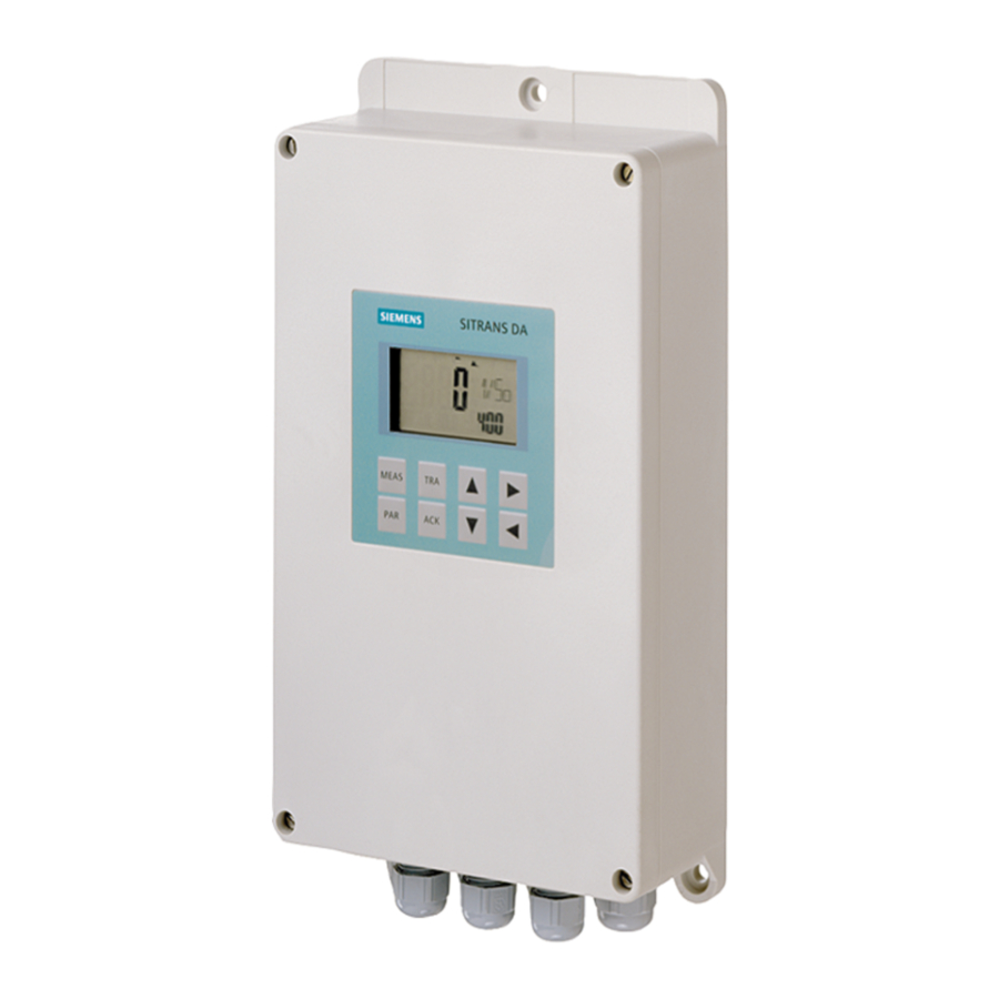
Description 3.3 Structure Structure 3.3.1 Device structure Figure 3-1 Front view (closed and open) Screwable cover Terminal connection diagram Nameplate Terminal strip Digital display Cable gland Keypad Mounting plate Sensor SITRANS DA400 with protection against explosion Operating Instructions, 02/2006, A5E00684661-01... -
Page 11: Structure Of The Nameplate
Explosion protection Place of manufacture Address for information Product information Sensor Manufacturer Address for information Order number Place of manufacture Product name Product information Serial number Explosion protection Product version SITRANS DA400 with protection against explosion Operating Instructions, 02/2006, A5E00684661-01... -
Page 12: How It Works
SITRANS DA400 on the outside. The SITRANS DA400 utilizes the fact that with both an open valve and a closed intact valve, no cavitation occurs and the measured sound level thus corresponds to the operating noise of the pump. -
Page 13: Operation Of The Electronics
3.3 V and 8.2 V for circuit 2. The supplementary voltage U obtained from the PROFIBUS-PA signal of an external coupler. Circuits 1 and 2 have split SITRANS DA400 with protection against explosion Operating Instructions, 02/2006, A5E00684661-01... - Page 14 "In 4". The switching of the four terminals is to be set up according to signal or sensor type (0/4 to 20 mA, digital signal for 24 V, closing contact). SITRANS DA400 with protection against explosion Operating Instructions, 02/2006, A5E00684661-01...
-
Page 15: Assembly
Mounting the device To mount the device, you need three screws with a diameter of 6 mm. These are not supplied with the device. SITRANS DA400 with protection against explosion Operating Instructions, 02/2006, A5E00684661-01... - Page 16 (with two valves). However, in this case it is not possible to distinguish which valve has a leak. The acoustic sensors are mounted at an equal spacing to the valves. SITRANS DA400 with protection against explosion Operating Instructions, 02/2006, A5E00684661-01...
-
Page 17: Connecting
All connecting leads inside the device should be kept short. To ensure the degree of protection according to IP65 for the device, only the permissible cable diameters may be used. SITRANS DA400 with protection against explosion Operating Instructions, 02/2006, A5E00684661-01... - Page 18 • To open the housing: Screwdriver for M4 slotted screws • For connecting terminals: Screwdriver for M2.5 slotted screws • Shielding connections: T10 screwdriver for M3 Torx screws • Grounding: T20 screwdriver for M4 Torx screws SITRANS DA400 with protection against explosion Operating Instructions, 02/2006, A5E00684661-01...
-
Page 19: Terminal Assignment
1. Unscrew the cover and place it next to the device. 2. Loosen the cable gland. 3. Remove the sealing stopper. 4. Connect the desired lead. 5. Tighten the cable gland. SITRANS DA400 with protection against explosion Operating Instructions, 02/2006, A5E00684661-01... -
Page 20: Connecting The Sensors
4. Connect the four lines to a four-way block, "Sens1" to "Sens4". Observe the color scheme. Cable color Terminal symbol Sensor 1 Sensor 2 Sensor 3 Sensor 4 Yellow Green Brown Black SITRANS DA400 with protection against explosion Operating Instructions, 02/2006, A5E00684661-01... -
Page 21: Connecting The Digital Outputs
Use only approved safe connector hardeners in conformity with DIN 19234, as described in the chapter "Technical data." See also Terminal assignment (Page 5-3) Cable gland (Page 5-3) Connect the ground (Page 5-10) Technical data for the device (Page 9-1) SITRANS DA400 with protection against explosion Operating Instructions, 02/2006, A5E00684661-01... -
Page 22: Connect The Signal Inputs
⊥ Connecting the 24 V digital signal Connect the signal line in accordance with the following table: Digital signal Terminal symbol In 1 In 2 In 3 In 4 ⊥ SITRANS DA400 with protection against explosion Operating Instructions, 02/2006, A5E00684661-01... - Page 23 Be careful that the closing contact is separated correctly from current circuits that are not intrinsically safe. See also Terminal assignment (Page 5-3) Cable gland (Page 5-3) Connect the ground (Page 5-10) Technical data for the device (Page 9-1) SITRANS DA400 with protection against explosion Operating Instructions, 02/2006, A5E00684661-01...
-
Page 24: Connect Profibus Pa
The use of shielded conduits for the PROFIBUS PA is absolutely necessary. As a matter of safety, all shields should be laid two-sided, and the feed source should be connected to the potential balance of the external area. SITRANS DA400 with protection against explosion Operating Instructions, 02/2006, A5E00684661-01... -
Page 25: Connecting The Power Supply
Use only approved safe feed sources, as described in the chapter "Technical Data." See also Terminal assignment (Page 5-3) Cable gland (Page 5-3) Connect the ground (Page 5-10) Technical data for the device (Page 9-1) SITRANS DA400 with protection against explosion Operating Instructions, 02/2006, A5E00684661-01... -
Page 26: Connect The Ground
Use only approved safe feed sources, as described in the chapter "Technical Data." The grounding connection of the item must be connected to the potential balance. SITRANS DA400 with protection against explosion 5-10 Operating Instructions, 02/2006, A5E00684661-01... - Page 27 In 1 to In 4. See also Terminal assignment (Page 5-3) Cable gland (Page 5-3) SITRANS DA400 with protection against explosion 5-11 Operating Instructions, 02/2006, A5E00684661-01...
- Page 28 Connecting 5.9 Connect the ground SITRANS DA400 with protection against explosion 5-12 Operating Instructions, 02/2006, A5E00684661-01...
-
Page 29: Operation
Parameters: call up the parameter menu <TRA> Trace: call up the trace menu to display and reset various timers <ACK> Acknowledge In the measurement menu: Acknowledge an alarm that has been set off SITRANS DA400 with protection against explosion Operating Instructions, 02/2006, A5E00684661-01... -
Page 30: Digital Display
In the middle section (2), the digital display shows the following, depending on the selected menu: • Measured value or fault symbol, parameter value, timer value (trace) • Channel number, parameter name, timer name (trace) SITRANS DA400 with protection against explosion Operating Instructions, 02/2006, A5E00684661-01... -
Page 31: Measuring Menu
6.3.2 Acoustic channels Introduction There are four channels for connection of acoustic sensors. They are shown as follows in the digital display: • 1/So1 • 2/So2 SITRANS DA400 with protection against explosion Operating Instructions, 02/2006, A5E00684661-01... - Page 32 Measuring menu digital display, acoustic channel fault Symbol for sensor fault Summation alarm, received from other acoustic channels Channel number The associated value of a major alarm; indicated starting with software version 1.03. SITRANS DA400 with protection against explosion Operating Instructions, 02/2006, A5E00684661-01...
-
Page 33: Universal Inputs
20-4 -> 20 mA = 0% / 4 mA = 100% This percentage value is displayed as the measured value and monitored for a configurable limit value (parameters P.30 to P.33). SITRANS DA400 with protection against explosion Operating Instructions, 02/2006, A5E00684661-01... - Page 34 "Lo" the symbol. Figure 6-6 Measuring menu digital display, digital value Measured value Lo or Hi Display for measured value Hi Summation alarm received from acoustic channels Channel number SITRANS DA400 with protection against explosion Operating Instructions, 02/2006, A5E00684661-01...
- Page 35 As P.15 Main alarm 4 P.23 doFAI As P.15 Input fault summation signal P.24 doFAu As P.15 Internal fault summation signal P.25 P ouT PoS / inv Output polarity SITRANS DA400 with protection against explosion Operating Instructions, 02/2006, A5E00684661-01...
-
Page 36: Setting Parameters
1. Press the <PAR> key for 5 seconds. "MEnu" and "PARAM" are shown in the middle section of the digital display. "MEnu" flashes. After these 5 seconds, the appearance of the digital display is as shown below. SITRANS DA400 with protection against explosion Operating Instructions, 02/2006, A5E00684661-01... -
Page 37: Parameter Lock
75 = 78 Line 4 P.29/IMP = noPA 85 = 88 If several inputs are set with a parameter with the function "noPA," the function will be activated upon switching on ("ORing"). SITRANS DA400 with protection against explosion Operating Instructions, 02/2006, A5E00684661-01... -
Page 38: Trace Menu
Hours.Minutes The resettable timer "oP-T" (operation time) can be used to Days.Hours display the operating time of the pump after re-installation or Years.Days repair. - - - - RESET SITRANS DA400 with protection against explosion 6-10 Operating Instructions, 02/2006, A5E00684661-01... -
Page 39: Displaying And Resetting The Timer
After these 5 seconds, the appearance of the digital display is as shown below. 2. Select the timer name using the keys. Note Timers for acoustic channels that are configured with "oFF" (possible for parameters P.1 to P.4) are not displayed. SITRANS DA400 with protection against explosion 6-11 Operating Instructions, 02/2006, A5E00684661-01... - Page 40 It is possible to reset all timers using the following setting in the trace menu: All the counters except the running time counter of the device are reset ("LIV-T" timer). See also Trace function (Page 7-8) SITRANS DA400 with protection against explosion 6-12 Operating Instructions, 02/2006, A5E00684661-01...
-
Page 41: Evaluating And Processing Signals
"P.13/Time". The same delay time also applies it the value is below the alarm values. When the main alarm responds, the pre-alarm is also activated. SITRANS DA400 with protection against explosion Operating Instructions, 02/2006, A5E00684661-01... -
Page 42: Evaluation Of Universal Inputs
The wiring and configuration (P.26 to P.29) should be adapted for the relevant signal type. See also Parameter table (Page 6-7) SITRANS DA400 with protection against explosion Operating Instructions, 02/2006, A5E00684661-01... -
Page 43: Evaluation Of Analog Current Signals
"P.30/ALI*" to "P.33/ALI*". The digital signal "dol*" is then obtained. If the state is "0", the symbol (alarm not received) is displayed, if the state is "1", the symbol (alarm received). SITRANS DA400 with protection against explosion Operating Instructions, 02/2006, A5E00684661-01... -
Page 44: Evaluation Of 24 V Digital Signals
Low or High level for the signal. The threshold value is set up so that a closing contact also generates a High signal via the 8.2 V source. With the parameter setting ¬24V, the digital signal is inverted. SITRANS DA400 with protection against explosion Operating Instructions, 02/2006, A5E00684661-01... -
Page 45: Processing Of Input Faults
The fault signal "doFAI" is created from the OR of the following input fault signals: • Fault in acoustic sensors • Universal input signal fault, e.g. >21 mA for analog current Figure 7-4 Input faults SITRANS DA400 with protection against explosion Operating Instructions, 02/2006, A5E00684661-01... -
Page 46: Actuation Of Digital Outputs
You can use the parameters P.15 to P.24 and P.34 to P.37 to select the digital output to be used to output the associated signal. You can also select whether the signal is to be output inverted. SITRANS DA400 with protection against explosion Operating Instructions, 02/2006, A5E00684661-01... - Page 47 Evaluating and processing signals 7.2 Evaluation of universal inputs Figure 7-5 Digital output function diagram * for digital outputs 1 to 6 SITRANS DA400 with protection against explosion Operating Instructions, 02/2006, A5E00684661-01...
-
Page 48: Trace Function
The measured value falls below the alarm value hysteresis and activates the time criterion "P.13/TIME" again. Time 8 The time "P13/TIME" has expired. The alarm is reset. Timer "A1-T" stops. SITRANS DA400 with protection against explosion Operating Instructions, 02/2006, A5E00684661-01... -
Page 49: Acknowledgement
Time 3: Alarm is only set if the alarm value is exceeded again. Time 4: Value below alarm value, alarm remains saved. Time 5: Acknowledgement with <ACK> key, alarm is reset. SITRANS DA400 with protection against explosion Operating Instructions, 02/2006, A5E00684661-01... - Page 50 Time 2: Acknowledgement with <ACK> key, alarm is reset. Time 3: Alarm is only set if the alarm value is exceeded again. Time 4: Value below alarm value and alarm canceled. Figure 7-7 Acknowledgement evaluation SITRANS DA400 with protection against explosion 7-10 Operating Instructions, 02/2006, A5E00684661-01...
-
Page 51: Starting Up
Notice Ensure that all electrical connections and the installation of the sensors have been carried out properly and the cover is closed. SITRANS DA400 with protection against explosion Operating Instructions, 02/2006, A5E00684661-01... - Page 52 • Solid matter stuck in valve In certain cases, depending on the design, mode of operation and the pumped medium, self- cleaning effects or self-correcting effects can occur, which cause the fault to disappear. SITRANS DA400 with protection against explosion Operating Instructions, 02/2006, A5E00684661-01...
-
Page 53: Commissioning After Repairs
If repairs have been carried out on damaged pump valves, the timers may need to be reset in the trace menu. To do this, execute the "Reset All" menu item. SITRANS DA400 with protection against explosion Operating Instructions, 02/2006, A5E00684661-01... - Page 54 Starting up 8.2 Commissioning after repairs SITRANS DA400 with protection against explosion Operating Instructions, 02/2006, A5E00684661-01...
-
Page 55: Technical Data
Universal input 24 V digital signal • Input resistance > 19 kΩ Signal level Low < 4.5 V or open Signal level High > 7 V Hysteresis > 1 V SITRANS DA400 with protection against explosion Operating Instructions, 02/2006, A5E00684661-01... - Page 56 Transmission disruption and resistance to • As per EN 61326 and NAMUR NE 21 disruption Usage limits for water Delivery side ≥ 10 bar a Number of strokes < 300 1/min SITRANS DA400 with protection against explosion Operating Instructions, 02/2006, A5E00684661-01...
- Page 57 Temperature class T4, T5 • -20° C to +60° C ( -4° F to 140° F) Temperature class T6 • -20° C to +50° C ( -4° F to 122° C) SITRANS DA400 with protection against explosion Operating Instructions, 02/2006, A5E00684661-01...
-
Page 58: Sensor For Technical Data
Class 4K4 according to DIN EN 60721-3-4 Mounting location Zone 0/1 or zone 20/21/22 Mechanical load Class 4M7 according to DIN EN 60721-3-4 Type of protection according to EN 60529 IP66/IP68 SITRANS DA400 with protection against explosion Operating Instructions, 02/2006, A5E00684661-01... - Page 59 Dimensions (W x L x H) in mm (inches) 26 x 40 x 29 (1.0 x 1.6 x 1.1) Auxiliary power Feed from intrinsically secure SITRANS DA400 3.3 V DC/< 5 mA For connection with approved intrinsically safe circuits with: Maximum feed voltage Ui •...
- Page 60 Technical data 9.2 Sensor for technical data SITRANS DA400 with protection against explosion Operating Instructions, 02/2006, A5E00684661-01...
-
Page 61: Dimension Diagrams
Dimension diagrams 10.1 SITRANS DA400 3 mounting holes (M6) Dimensions in mm (inch) SITRANS DA400 with protection against explosion 10-1 Operating Instructions, 02/2006, A5E00684661-01... -
Page 62: Sensor
Dimension diagrams 10.2 Sensor 10.2 Sensor Dimensions in mm (inch) SITRANS DA400 with protection against explosion 10-2 Operating Instructions, 02/2006, A5E00684661-01... -
Page 63: Profibus Pa
PROFIBUS master of class 1 (principally all possible baud rates and the number of input and output bytes). You can integrate the diagnosis setup SITRANS DA400 into a projection tool using the device core file. - Page 64 1 byte 1 byte Universal input 3 (digital) 1 byte 1 byte Universal input 4 (digital) 1 byte 1 byte Digital outputs D01 to D06 1 byte 1 byte SITRANS DA400 with protection against explosion 11-2 Operating Instructions, 02/2006, A5E00684661-01...
- Page 65 1 byte Measurement status Format of the digital input data (slots 9 to 12, Dl1 to Dl8): 1 byte Digital signal 0x00 (low) or 0x01 (high) 1 byte Measurement status SITRANS DA400 with protection against explosion 11-3 Operating Instructions, 02/2006, A5E00684661-01...
-
Page 66: Expanded Diagnosis
The error conditions are given in text in "HW Konfig". The core file of the item (GSD) provides the text for these messages. SITRANS DA400 with protection against explosion 11-4 Operating Instructions, 02/2006, A5E00684661-01... - Page 67 Input signal out of range Universal input 1 failure Possible causes: Supply broken Universal input 1 failure Connected resizer out of order Universal input 1 failure Measured value out of the measurement area SITRANS DA400 with protection against explosion 11-5 Operating Instructions, 02/2006, A5E00684661-01...
- Page 68 SITRANS DA400 with protection against explosion Operating Instructions, 02/2006, A5E00684661-01...