Siemens SITRANS DA400 Operating Instructions Manual
Process monitoring
Hide thumbs
Also See for SITRANS DA400:
- Operating instructions manual (86 pages) ,
- Operating instructions manual (68 pages) ,
- Operating instructions manual (104 pages)
Table of Contents
Advertisement
Quick Links
SITRANS
Process monitoring
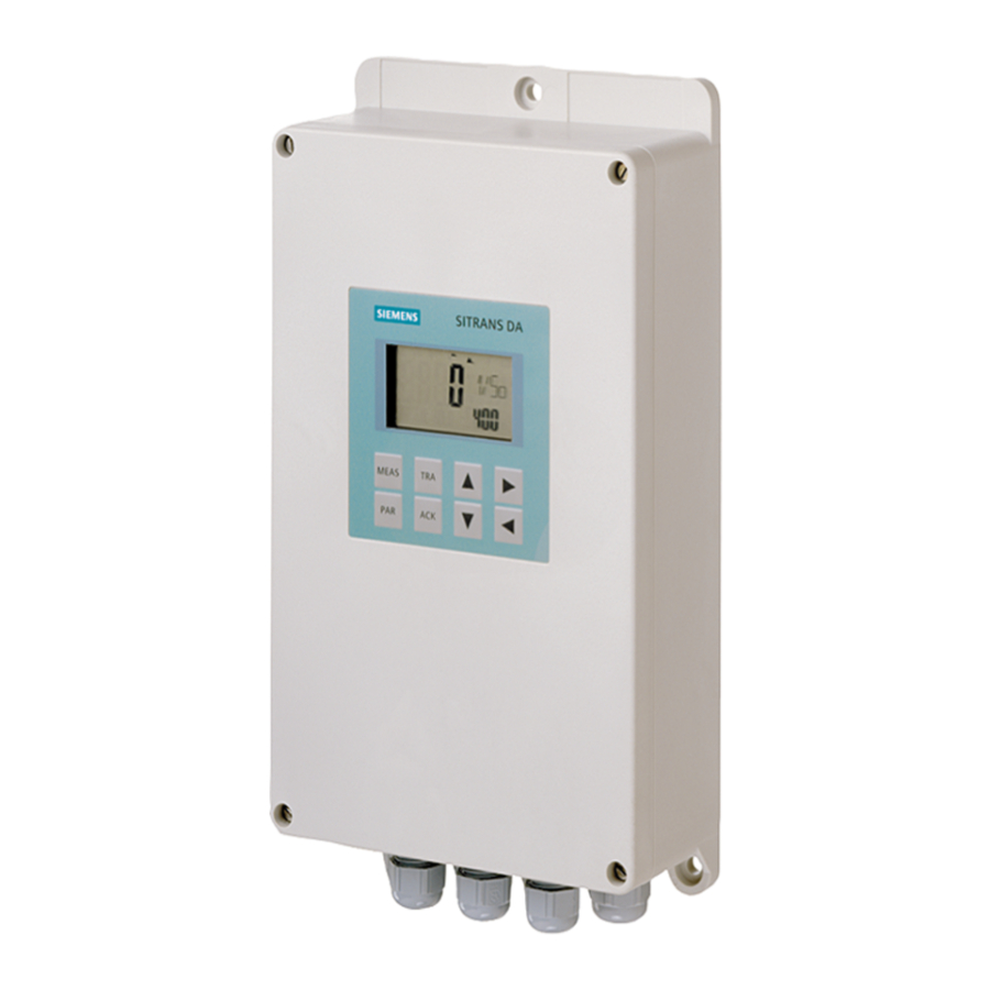
SITRANS DA400 for material flow
monitoring with protection against
explosion
Operating Instructions
7MJ2400-2BA02 device with protection against explosion
7MJ2000-1B*00 sensor with protection against explosion
09/2007
A5E00841152-01
Introduction
General safety notes
Description
Assembly
Connecting
Operation
Signal processing
Commissioning
Technical data
Dimension drawings
PROFIBUS PA
1
2
3
4
5
6
7
8
9
10
11
Advertisement
Table of Contents

Related Manuals for Siemens SITRANS DA400


Summary of Contents for Siemens SITRANS DA400
- Page 1 Introduction General safety notes Description SITRANS Assembly Process monitoring SITRANS DA400 for material flow Connecting monitoring with protection against explosion Operation Operating Instructions Signal processing Commissioning Technical data Dimension drawings PROFIBUS PA 7MJ2400-2BA02 device with protection against explosion 7MJ2000-1B*00 sensor with protection against explosion...
- Page 2 Trademarks All names identified by ® are registered trademarks of the Siemens AG. The remaining trademarks in this publication may be trademarks whose use by third parties for their own purposes could violate the rights of the owner.
-
Page 3: Table Of Contents
Connecting .............................. 23 Safety notes and conditions......................23 Terminal assignment........................25 Cable gland ..........................26 Connecting structure-borne sound sensors.................27 Connecting the digital outputs......................28 Connecting signal inputs......................29 Connect PROFIBUS PA ......................31 SITRANS DA400 for material flow monitoring with protection against explosion Operating Instructions, 09/2007, A5E00841152-01... - Page 4 8.2.1 Preparation..........................74 8.2.2 Damping using parameters P.41, P.42, P.43 and P.44 .............. 74 8.2.3 Main alarm threshold via parameters P.6, P.8, P.10 and P.12........... 74 SITRANS DA400 for material flow monitoring with protection against explosion Operating Instructions, 09/2007, A5E00841152-01...
- Page 5 Dimension drawing of the device ....................85 10.2 Dimension drawing of the sensor....................86 PROFIBUS PA ............................87 11.1 System integration ........................87 11.2 Projection .............................88 11.3 Expanded diagnosis........................92 Index................................ 93 SITRANS DA400 for material flow monitoring with protection against explosion Operating Instructions, 09/2007, A5E00841152-01...
- Page 6 Table of contents SITRANS DA400 for material flow monitoring with protection against explosion Operating Instructions, 09/2007, A5E00841152-01...
-
Page 7: Introduction
The contents of these instructions shall not become part of or modify any prior or existing agreement, commitment or legal relationship. All obligations on the part of Siemens AG are contained in the respective sales contract which also contains the complete and solely applicable warranty conditions. -
Page 8: History
Regulations of the Member States on Devices and Protective Systems for defined use in areas subject to explosion. This is communicated by the CE label. D-76181 Karlsruhe SITRANS DA400 for material flow monitoring with protection against explosion Operating Instructions, 09/2007, A5E00841152-01... -
Page 9: General Safety Notes
● National Electrical Code (NEC - NFPA 70) (USA) ● Canadian Electrical Code (CEC) (Canada) ● EN 60079-14 (formerly VDE 0165, T1) (EU, Germany) ● The working reliability regulation (Germany) SITRANS DA400 for material flow monitoring with protection against explosion Operating Instructions, 09/2007, A5E00841152-01... -
Page 10: Measures
● They are trained or instructed in maintenance and use of appropriate safety equipment according to the safety regulations. SITRANS DA400 for material flow monitoring with protection against explosion Operating Instructions, 09/2007, A5E00841152-01... -
Page 11: Description
– aerated gravity flow systems Operation You can operate and configure the SITRANS DA400 using the keys. In parallel, you can also operate the SITRANS DA400 via a PROFIBUS connection. SITRANS DA400 for material flow monitoring with protection against explosion... -
Page 12: Design
Front view (closed and open) ① Screwable cover ⑥ Terminal connection diagram ② Nameplate ⑦ Terminal strip ③ Digital display ⑧ Cable gland ④ Keypad ⑨ Mounting plate ⑤ Sensor SITRANS DA400 for material flow monitoring with protection against explosion Operating Instructions, 09/2007, A5E00841152-01... -
Page 13: Structure Of The Nameplate
Place of manufacture Address for information Product information Sensor Manufacturer Address for information Order number Place of manufacture Product name Product information Serial number Explosion protection Product version SITRANS DA400 for material flow monitoring with protection against explosion Operating Instructions, 09/2007, A5E00841152-01... -
Page 14: Mode Of Operation
Therefore, the sensor does not sense background noise and allows for non-invasive process and equipment monitoring. The SITRANS DA400 provides a measuring value in the form of sound level L, which is dependent on the acoustic power. The sound level L produced by the material flow is dependent on the mechanical power. -
Page 15: Sensor Operation
The sensor frequency range lies in the ultrasonic range (>20 kHz). The sensor is non- directional, i.e. the angle at which the sound wave is incident on the sensor base is not important. SITRANS DA400 for material flow monitoring with protection against explosion Operating Instructions, 09/2007, A5E00841152-01... -
Page 16: Operation Of The Electronics
Power supply (any polarity) Analog current input + Power supply (any polarity) ⊥ Mass Digital output Digital input Sens Sensor PROFIBUS PA (any polarity) input PROFIBUS PA (any polarity) SITRANS DA400 for material flow monitoring with protection against explosion Operating Instructions, 09/2007, A5E00841152-01... - Page 17 "In 4". The switching of the four terminals is to be set up according to signal or sensor type (0/4 to 20 mA, digital signal for 24 V, closing contact). SITRANS DA400 for material flow monitoring with protection against explosion Operating Instructions, 09/2007, A5E00841152-01...
- Page 18 Description 3.4 Mode of operation SITRANS DA400 for material flow monitoring with protection against explosion Operating Instructions, 09/2007, A5E00841152-01...
-
Page 19: Assembly
Fire hazard resulting from hot surfaces. When installing the sensor, take note of the surface temperature of the installation site. Overview The SITRANS DA400 and the sensor are mounted in different ways. In general: Note Protection against harmful outside influences To protect the SITRANS DA400 against harmful outside influences, a housing should be fitted. -
Page 20: Mounting The Acoustic Emission Sensor
If necessary, use a viscous lubricating grease to improve the coupling. The lubricating grease is not included in the scope of delivery. The following figure demonstrates an optimal mounting of the acoustic emission sensor: SITRANS DA400 for material flow monitoring with protection against explosion Operating Instructions, 09/2007, A5E00841152-01... - Page 21 4.3 Mounting the acoustic emission sensor Figure 4-1 Optimal mounting of a acoustic emission sensor ① Acoustic emission sensor ② Connection cable ③ Pipe ④ Flow direction SITRANS DA400 for material flow monitoring with protection against explosion Operating Instructions, 09/2007, A5E00841152-01...
- Page 22 Assembly 4.3 Mounting the acoustic emission sensor SITRANS DA400 for material flow monitoring with protection against explosion Operating Instructions, 09/2007, A5E00841152-01...
-
Page 23: Connecting
(previously VDE 0165, T1) If auxiliary power is required, check that it corresponds with that on the nameplate and with the test certification valid for your country. SITRANS DA400 for material flow monitoring with protection against explosion Operating Instructions, 09/2007, A5E00841152-01... - Page 24 ● For connecting terminals: Screwdriver for M2.5 slotted screws ● Shielding connections: T10 screwdriver for M3 Torx screws ● Grounding: T20 screwdriver for M4 Torx screws SITRANS DA400 for material flow monitoring with protection against explosion Operating Instructions, 09/2007, A5E00841152-01...
-
Page 25: Terminal Assignment
Analog current input + Sens Sensor ⊥ Mass Input Digital input Yellow PROFIBUS PA (any polarity) Green PROFIBUS PA (any polarity) See also Connecting the power supply (Page 32) SITRANS DA400 for material flow monitoring with protection against explosion Operating Instructions, 09/2007, A5E00841152-01... -
Page 26: Cable Gland
Cable gland for sensors 1 and 3 ⑦ Cable gland for power supply L+ and L- and earthing See also Connecting structure-borne sound sensors (Page 27) Connecting the power supply (Page 32) SITRANS DA400 for material flow monitoring with protection against explosion Operating Instructions, 09/2007, A5E00841152-01... -
Page 27: Connecting Structure-Borne Sound Sensors
Sensor 1 Sensor 2 Sensor 3 Sensor 4 Yellow Green Brown Black See also Cable gland (Page 26) Terminal assignment (Page 25) Connect the ground (Page 33) SITRANS DA400 for material flow monitoring with protection against explosion Operating Instructions, 09/2007, A5E00841152-01... -
Page 28: Connecting The Digital Outputs
DO 4 DO 5 DO 6 See also Terminal assignment (Page 25) Cable gland (Page 26) Device technical data (Page 77) Connect the ground (Page 33) SITRANS DA400 for material flow monitoring with protection against explosion Operating Instructions, 09/2007, A5E00841152-01... -
Page 29: Connecting Signal Inputs
Connecting the 24 V digital signal Connect the signal line in accordance with the following table: Digital signal Terminal symbol In 1 In 2 In 3 In 4 ⊥ SITRANS DA400 for material flow monitoring with protection against explosion Operating Instructions, 09/2007, A5E00841152-01... - Page 30 In 4 Contact 1 Contact 2 See also Terminal assignment (Page 25) Cable gland (Page 26) Device technical data (Page 77) Connect the ground (Page 33) SITRANS DA400 for material flow monitoring with protection against explosion Operating Instructions, 09/2007, A5E00841152-01...
-
Page 31: Connect Profibus Pa
PROFIBUS cable, dimensions in mm (inches) ➀ Bus cable ② Cable shield See also Terminal assignment (Page 25) Cable gland (Page 26) Connect the ground (Page 33) SITRANS DA400 for material flow monitoring with protection against explosion Operating Instructions, 09/2007, A5E00841152-01... -
Page 32: Connecting The Power Supply
Use only approved intrinsically safe power sources, as described in the "Technical data" section. See also Terminal assignment (Page 25) Cable gland (Page 26) Device technical data (Page 77) Connect the ground (Page 33) SITRANS DA400 for material flow monitoring with protection against explosion Operating Instructions, 09/2007, A5E00841152-01... -
Page 33: Connect The Ground
In order to connect the ground, proceed as follows: 1. Guide the earth cable through the cable gland ⑦. 2. Connect the grounding cable to the grounding screw on the mounting plate. SITRANS DA400 for material flow monitoring with protection against explosion Operating Instructions, 09/2007, A5E00841152-01... - Page 34 In 1 to In 4. See also Connecting structure-borne sound sensors (Page 27) Connect PROFIBUS PA (Page 31) Cable gland (Page 26) SITRANS DA400 for material flow monitoring with protection against explosion Operating Instructions, 09/2007, A5E00841152-01...
-
Page 35: Operation
All important information on the parameters is described in the parameter list in the "Parameter list" section. Digital display and buttons Figure 6-1 Digital display and buttons SITRANS DA400 for material flow monitoring with protection against explosion Operating Instructions, 09/2007, A5E00841152-01... - Page 36 Scroll forwards in measurement channel list, parameter list and trace list Scroll backwards in measurement channel list, parameter list and trace list See also Parameter list (Page 49) SITRANS DA400 for material flow monitoring with protection against explosion Operating Instructions, 09/2007, A5E00841152-01...
-
Page 37: Digital Display
In the lower section ③, the digital display shows the following, depending on the selected menu: ● PAR in parameter menu only ● Value for main alarm or limit value, parameter number, time unit in trace menu. SITRANS DA400 for material flow monitoring with protection against explosion Operating Instructions, 09/2007, A5E00841152-01... -
Page 38: Measuring Menu
③ Pre-alarm received ⑦ Number and name of the measurement channel ④ Main alarm not received ⑧ Value of the main alarm threshold in measuring mode SITRANS DA400 for material flow monitoring with protection against explosion Operating Instructions, 09/2007, A5E00841152-01... -
Page 39: Measurement Channel List
Measurement channels configured with "oFF" are not displayed. This is set in the parameters P.1 to P.4 and P.26 to P.29. If all measurement channels are "oFF", "oFF/ALL" appears in the digital display. SITRANS DA400 for material flow monitoring with protection against explosion Operating Instructions, 09/2007, A5E00841152-01... - Page 40 The digital display is tested as follows: Press the <MEAS> button. If all elements of the digital display are visible, the digital display is functioning correctly. SITRANS DA400 for material flow monitoring with protection against explosion Operating Instructions, 09/2007, A5E00841152-01...
-
Page 41: Acoustic Channels
If no alarm was set, "noAL" is shown to the left in the middle section of the digital display. Note Condition Alarms can only be acknowledged if the parameter value is set to "P.14/ACK" = "¬St.Ac" or "St.Ac". SITRANS DA400 for material flow monitoring with protection against explosion Operating Instructions, 09/2007, A5E00841152-01... -
Page 42: Simulation Mode
Simulated measured value in dB; flashes if main alarm received 1/So1 Set measured channel 1 SIMU Note that the simulation mode is active. Procedure In order to simulate the measured values, proceed as follows: SITRANS DA400 for material flow monitoring with protection against explosion Operating Instructions, 09/2007, A5E00841152-01... - Page 43 Note Timers If pre or main alarms are set in simulation mode, the timers count the trace function. If necessary, set the counters back manually. SITRANS DA400 for material flow monitoring with protection against explosion Operating Instructions, 09/2007, A5E00841152-01...
-
Page 44: Test Mode
The digital display appears as follows: Middle section: tESt SoCH1 Lower section: PAR P. 1 Test mode is set. SITRANS DA400 for material flow monitoring with protection against explosion Operating Instructions, 09/2007, A5E00841152-01... -
Page 45: Universal Inputs
See also Parameter list (Page 49) 6.3.5 Universal inputs 6.3.5.1 General The four universal inputs are used to monitor analog signals and digital signals for limit values. SITRANS DA400 for material flow monitoring with protection against explosion Operating Instructions, 09/2007, A5E00841152-01... -
Page 46: Analog Input
Summation alarm received from acoustic channels. ④ Number and name of the measurement channel ⑤ Associated limit value (here, parameter "P.30/ALI1"). See also Parameter list (Page 49) SITRANS DA400 for material flow monitoring with protection against explosion Operating Instructions, 09/2007, A5E00841152-01... -
Page 47: Digital Input
② Hi limit value exceeded ③ Summation alarm received from acoustic channels ④ Number and name of the measurement channel See also Parameter list (Page 49) SITRANS DA400 for material flow monitoring with protection against explosion Operating Instructions, 09/2007, A5E00841152-01... -
Page 48: Parameter Menu
Elements of the digital display in the parameter menu Figure 6-10 Parameter menu digital display ➀ Parameter value ② Parameter name ③ Parameter number SITRANS DA400 for material flow monitoring with protection against explosion Operating Instructions, 09/2007, A5E00841152-01... -
Page 49: Parameter List
As P.15 Pre-alarm 4 P.22 doAL4 As P.15 Main alarm 4 P.23 doFAI As P.15 Input fault summation signal P.24 doFAu As P.15 Internal fault summation signal SITRANS DA400 for material flow monitoring with protection against explosion Operating Instructions, 09/2007, A5E00841152-01... - Page 50 0 to 30 Low-pass filter time acoustic channel 3 P.44 DMP4 0 to 30 Low-pass filter time acoustic channel 4 See also Parameter lock (Page 52) SITRANS DA400 for material flow monitoring with protection against explosion Operating Instructions, 09/2007, A5E00841152-01...
-
Page 51: Setting Parameters
When the parameter P.0 is selected, "xx.yy" (e.g., "3.00") appears in the digital display. By simultaneously pressing the buttons, ". .zz" (e.g. ". .01") appears in the digital display. SITRANS DA400 for material flow monitoring with protection against explosion Operating Instructions, 09/2007, A5E00841152-01... -
Page 52: Parameter Lock
● Times at which the alarms were activated Elements of the digital display in the trace menu Figure 6-11 Trace menu digital display ➀ Timer value ② Timer name SITRANS DA400 for material flow monitoring with protection against explosion Operating Instructions, 09/2007, A5E00841152-01... - Page 53 Operation 6.5 Trace menu ③ Time unit SITRANS DA400 for material flow monitoring with protection against explosion Operating Instructions, 09/2007, A5E00841152-01...
-
Page 54: Trace Menu List
RESET 0 to 60 LIV-T Not resettable. Hours.Minutes The LIV-T Timer (live time) is not resettable, and shows the Days.Hours running time of the device. Years.Days SITRANS DA400 for material flow monitoring with protection against explosion Operating Instructions, 09/2007, A5E00841152-01... - Page 55 This is the time before the sounding of the final alarm, in which the associated alarm limit is exceeded. This is the accumulated time since the associated alarm was received. SITRANS DA400 for material flow monitoring with protection against explosion Operating Instructions, 09/2007, A5E00841152-01...
-
Page 56: Displaying And Resetting Timers
● Trigger a measured value alarm in the event of a sensor fault. ● A pre-alarm from measured value 20 dB. ● A master alarm from measured value 40 dB. ● Alarm after value exceeded for 60 s. SITRANS DA400 for material flow monitoring with protection against explosion Operating Instructions, 09/2007, A5E00841152-01... - Page 57 "doAL1". Main alarms are reported with digital output 1. See also Connecting structure-borne sound sensors (Page 27) Connecting signal inputs (Page 29) SITRANS DA400 for material flow monitoring with protection against explosion Operating Instructions, 09/2007, A5E00841152-01...
-
Page 58: Example Universal Input 1
The alarm limits set via parameters P.30 to P.33 are only effective with analog inputs. With digital inputs, the values given in the "Specification" apply as switching thresholds. SITRANS DA400 for material flow monitoring with protection against explosion Operating Instructions, 09/2007, A5E00841152-01... -
Page 59: Signal Processing
1. Calculation of the measured value as shown in the "Block diagram for calculation of the measured value" figure. 2. Formation of the alarm messages as shown in "Block diagram for the formation of alarm messages" figure. SITRANS DA400 for material flow monitoring with protection against explosion Operating Instructions, 09/2007, A5E00841152-01... - Page 60 ● The maximum value in test mode. ● The low-filtered sound level in normal measurement mode. Figure 7-1 Block diagram for calculation of the measured value SITRANS DA400 for material flow monitoring with protection against explosion Operating Instructions, 09/2007, A5E00841152-01...
- Page 61 In the event of a sensor fault (cable failure), the alarm for the damaged channel will be generated in addition to the fault summation message depending on configuration (P.1, P.2, P.3, P.4). Figure 7-2 Block diagram for formation of the alarm messages SITRANS DA400 for material flow monitoring with protection against explosion Operating Instructions, 09/2007, A5E00841152-01...
-
Page 62: Universal Input Evaluation
"P.30/ALI*" to "P.33/ALI*". The digital signal "dol*" is then obtained. If the state is "0", the symbol (alarm not received) is displayed, if the state is "1", the symbol (alarm received). SITRANS DA400 for material flow monitoring with protection against explosion Operating Instructions, 09/2007, A5E00841152-01... - Page 63 Signal processing 7.2 Universal input evaluation Figure 7-3 Universal input function diagram SITRANS DA400 for material flow monitoring with protection against explosion Operating Instructions, 09/2007, A5E00841152-01...
-
Page 64: Evaluation Of 24 V Digital Signals
"¬24 V", the digital signal is inverted. Figure 7-4 24 V digital signal function diagram See also Evaluation of analog current signals (Page 62) SITRANS DA400 for material flow monitoring with protection against explosion Operating Instructions, 09/2007, A5E00841152-01... -
Page 65: Processing Input Faults
The fault signal "doFAI" is created from the OR of the following input fault messages: ● Failure of the acoustic emission sensors ● Universal input signal fault, e.g. > 21 mA for analog current Figure 7-5 Input faults SITRANS DA400 for material flow monitoring with protection against explosion Operating Instructions, 09/2007, A5E00841152-01... -
Page 66: Activation Of Digital Outputs
You can use the parameters P.15 to P.24 and P.34 to P.37 to select the digital output to be used to output the associated signal. You can also select whether the signal is to be output inverted. SITRANS DA400 for material flow monitoring with protection against explosion Operating Instructions, 09/2007, A5E00841152-01... - Page 67 Signal processing 7.4 Activation of digital outputs Figure 7-6 Digital output function diagram * for digital outputs 1 to 6 SITRANS DA400 for material flow monitoring with protection against explosion Operating Instructions, 09/2007, A5E00841152-01...
- Page 68 The main alarm on acoustic channel 4 is output inverted on digital output 6. Note The parameter "P.25/P ouT" reverses the direction of action for all outputs. SITRANS DA400 for material flow monitoring with protection against explosion Operating Instructions, 09/2007, A5E00841152-01...
-
Page 69: Alarm Acknowledgement
Time 3: Alarm is only set if the alarm value is exceeded again. Time 4: Value below alarm value and alarm canceled. Figure 7-7 Acknowledgement evaluation SITRANS DA400 for material flow monitoring with protection against explosion Operating Instructions, 09/2007, A5E00841152-01... -
Page 70: Trace Function
The measured value falls below the alarm value hysteresis and activates the time criterion "P.13/TIME" again. Time 8 The time "P13/TIME" has expired. The alarm is reset. Timer "A1-T" stops. SITRANS DA400 for material flow monitoring with protection against explosion Operating Instructions, 09/2007, A5E00841152-01... - Page 71 Signal processing 7.6 Trace function Figure 7-8 Trace evaluation SITRANS DA400 for material flow monitoring with protection against explosion Operating Instructions, 09/2007, A5E00841152-01...
- Page 72 Signal processing 7.6 Trace function SITRANS DA400 for material flow monitoring with protection against explosion Operating Instructions, 09/2007, A5E00841152-01...
-
Page 73: Commissioning
Ensure that all electrical connections and the installation of the sensors have been carried out properly and the cover is closed. Note Regularly check the settings defined after the commissioning and correct them if necessary. SITRANS DA400 for material flow monitoring with protection against explosion Operating Instructions, 09/2007, A5E00841152-01... -
Page 74: Recommendation For Selecting Parameters
In this case, use a pre-alarm if necessary. Set the limit value for the main alarm at a value which is around 3 dB over the largest of the measured values read off. SITRANS DA400 for material flow monitoring with protection against explosion Operating Instructions, 09/2007, A5E00841152-01... -
Page 75: Pre-Alarm Threshold Via Parameters P.5, P.7, P.9 And
Commissioning after a repair After a repair, you have to reset the timer in the trace menu, if necessary. Use the the menu item "Reset All". SITRANS DA400 for material flow monitoring with protection against explosion Operating Instructions, 09/2007, A5E00841152-01... - Page 76 Commissioning 8.2 Recommendation for selecting parameters SITRANS DA400 for material flow monitoring with protection against explosion Operating Instructions, 09/2007, A5E00841152-01...
-
Page 77: Technical Data
0.1 % Accuracy • 0.5 % Fault message • > 21 mA or< 3.6 mA (at 4 ... 20 mA) Alarm monitoring hysteresis • 0.5 % SITRANS DA400 for material flow monitoring with protection against explosion Operating Instructions, 09/2007, A5E00841152-01... - Page 78 ≤ 5 mW External inductance L • 100 mH 5.00 mH 1.00 mH 0.20 mH External capacity C • 0.57 µF 0.79 µF 1.08 µF 1.58 µF SITRANS DA400 for material flow monitoring with protection against explosion Operating Instructions, 09/2007, A5E00841152-01...
- Page 79 Class 4M3 according to EN 60721-3-4 Degree of protection according to EN 60 529 IP65 Electromagnetic compatibility Spurious emission and interference immunity • According to EN 61326 SITRANS DA400 for material flow monitoring with protection against explosion Operating Instructions, 09/2007, A5E00841152-01...
- Page 80 Temperature class T4, T5 • -20 °C ... +60 °C (-4 °F ... 140 °F) Temperature class T6 • -20 °C ... +50 °C (-4 °F ... 122 °F) SITRANS DA400 for material flow monitoring with protection against explosion Operating Instructions, 09/2007, A5E00841152-01...
- Page 81 PROFIBUS PA profile V3.0 Rev. 1, Class B Device address • 1 ... 126; 126 (delivery state) PC configuration software SIMATIC PDM (not supplied with the device) SITRANS DA400 for material flow monitoring with protection against explosion Operating Instructions, 09/2007, A5E00841152-01...
-
Page 82: Sensor Technical Data
-40 °C to +80 °C -40 °C to +110 °C Use as category 1 D device or as T160 -40 °C to +110 °C • category 2 D device SITRANS DA400 for material flow monitoring with protection against explosion Operating Instructions, 09/2007, A5E00841152-01... - Page 83 Maximum current I • 204 mA Maximum power P • 200 mW Internal capacity C • ≤ 200 nF Internal inductance L • ≤ 500 μH SITRANS DA400 for material flow monitoring with protection against explosion Operating Instructions, 09/2007, A5E00841152-01...
- Page 84 Technical data 9.2 Sensor technical data SITRANS DA400 for material flow monitoring with protection against explosion Operating Instructions, 09/2007, A5E00841152-01...
-
Page 85: Dimension Drawings
Dimension drawings 10.1 Dimension drawing of the device 3 mounting holes (M6) Dimensions in mm (inch) SITRANS DA400 for material flow monitoring with protection against explosion Operating Instructions, 09/2007, A5E00841152-01... -
Page 86: Dimension Drawing Of The Sensor
Dimension drawings 10.2 Dimension drawing of the sensor 10.2 Dimension drawing of the sensor Dimensions in mm (inches) SITRANS DA400 for material flow monitoring with protection against explosion Operating Instructions, 09/2007, A5E00841152-01... -
Page 87: Profibus Pa
PROFIBUS master of class 1 (principally all possible baud rates and the number of input and output bytes). You can integrate the diagnosis setup SITRANS DA400 into a projection tool using the device core file. -
Page 88: Projection
11.2 Projection 11.2 Projection The following illustrations describe a projection with "HW Konfig" from SIMATIC S7. The projection as presented is logically transferable to other systems. SITRANS DA400 for material flow monitoring with protection against explosion Operating Instructions, 09/2007, A5E00841152-01... - Page 89 Universal input 3 (digital) 1 byte 1 byte Universal input 4 (digital) 1 byte 1 byte Digital outputs D01 to D06 1 byte 1 byte Analog input Digital input SITRANS DA400 for material flow monitoring with protection against explosion Operating Instructions, 09/2007, A5E00841152-01...
- Page 90 Format of the digital input data (slots 9 to 12, Dl1 to Dl8): 1 byte Digital signal 0x00 (low) or 0x01 (high) 1 byte Measurement status SITRANS DA400 for material flow monitoring with protection against explosion Operating Instructions, 09/2007, A5E00841152-01...
- Page 91 With the "Fail safe type" object of the associated input-block = 0 or 1 For the "fail safe type" of the associated input block = 1 if no applicable substitute value is available. SITRANS DA400 for material flow monitoring with protection against explosion Operating Instructions, 09/2007, A5E00841152-01...
-
Page 92: Expanded Diagnosis
Universal input 1 failure Supply broken Universal input 1 failure Connected resizer out of order Universal input 1 failure Measured value out of the measurement area SITRANS DA400 for material flow monitoring with protection against explosion Operating Instructions, 09/2007, A5E00841152-01... -
Page 93: Index
Hazardous area, 9 Test certification, 9 History, 8 Type of protection Intrinsic safety, 10 Limited energy nL (zone 2), 10 non-sparking nA (zone 2), 10 Intrinsic safety, 10 SITRANS DA400 for material flow monitoring with protection against explosion Operating Instructions, 09/2007, A5E00841152-01... - Page 94 Index Working reliability regulation, 9 Zone 2, 10 worldwide Contact person, 7 Worldwide contact person, 7 SITRANS DA400 for material flow monitoring with protection against explosion Operating Instructions, 09/2007, A5E00841152-01...