Siemens SONOLINE G20 Installation Instructions Manual
Hide thumbs
Also See for SONOLINE G20:
- Quick reference manual (5 pages) ,
- Maintenance instruction (12 pages)
Advertisement
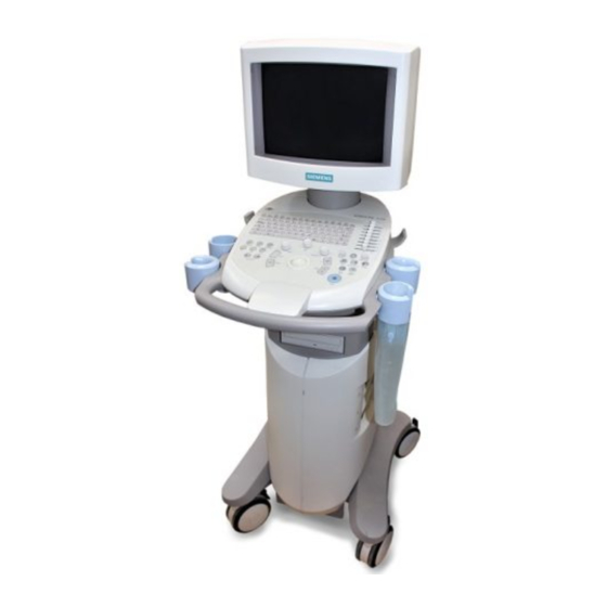
SONOLINE G20
Installation Instructions
System
SONOLINE G20 System Delivery Procedure
08647831
08647815
ejt
Ultrasound Division
Siemens Medical Solutions
Print No.:
US06-101.812.01.02.02
Replaces: US06-101.812.01.01.02
Part No.:
sd
US
2004
© Siemens AG
The reproduction, transmission or use
of this document or its contents is not
permitted
without
express
written
authority. Offenders will be liable for
damages. All rights, including rights
created by patent grant or registration
of a utility model or design, are
reserved.
English
Doc. Gen. Date: 10.04
n.a.
Advertisement
Table of Contents

Related Manuals for Siemens SONOLINE G20


Summary of Contents for Siemens SONOLINE G20
- Page 1 SONOLINE G20 Installation Instructions System SONOLINE G20 System Delivery Procedure 08647815 08647831 2004 © Siemens AG The reproduction, transmission or use of this document or its contents is not permitted without express written authority. Offenders will be liable for Siemens Medical Solutions Ultrasound Division damages.
- Page 2 Assemblers and other persons who are not employed by or otherwise directly affiliated with or authorized by Siemens or one of its affiliates are directed to contact one of the local offices of Siemens or one of its affiliates before attempting installation or service pro- cedures.
- Page 3 Buyer with respect to software supplied by such supplier, and (ii) No supplier of Siemens shall be liable to buyer for any general, special, direct, indi- rect, consequential, incidental or other damages arising out of the sublicense of the com- puter programs supplied with the equipment.
-
Page 4: Table Of Contents
0Table of Contents 1 _______ SONOLINE G20 System Delivery Procedure__________________________ 5 Uncrate the system and peripherals ......... 6 Prior to Starting . - Page 5 SONOLINE G20 System Delivery Procedure 1SONOLINE G20 System Delivery Procedure This section provides instructions to perform a courtesy check for the SONOLINE G20™ ultrasound system. The courtesy check includes: • Uncrate the System and Peripherals • Power On the System •...
-
Page 6: Uncrate The System And Peripherals
Unpack the System 1. Check the shipping container for damage caused during shipment. NOTE Notify Siemens Uptime Service Center if damage to the shipping container is found. 2. Remove the shipping documentation from the outside of the shipping container. Set them aside for the customer. - Page 7 SONOLINE G20 System Delivery Procedure 4. Release and remove the three Corro clips, located on the front of the shipping contain- - To release the clip, squeeze the two vertical bars together and then pull the top of the bars down and away from the clip.
- Page 8 SONOLINE G20 System Delivery Procedure 6. Install the two roll-out ramps. - Place the two ramps on the ramp studs. The ramps studs are located on the front side of the shipping crate. The ramp planks have one hole at the end that is placed on the floor and two holes at the end that is placed on the ramp stud.
-
Page 9: Verify The Receipt Of Accessories
SONOLINE G20 System Delivery Procedure Verify the Receipt of Accessories 1. Inspect the accessories and other material in the accessory box. Quantity Accessory Power Cord, 115 V Power Cord, 230 V Gel Bottle 1-container 1-set CD-ROM, System Disk CD-ROM, OS-System Disk... -
Page 10: Power On The System
SONOLINE G20 System Delivery Procedure Power On the System 1. Attach the power cord safety lock to the system. - Verify that the MAINS power switch is off. - Choose the correct power cord and safety lock for the system (100V/115V or 230V). - Page 11 SONOLINE G20 System Delivery Procedure 3. Power on the MAINS power switch (up is on and down is off). The Standby button is backlit with the color amber when the MAINS power is switched to on. Fig. 7: Back of the System -Power Pos.
- Page 12 Pos. 6 Pos. 7 Pos. 8 On or off - depending on control panel status Pos. V NOTE If the LEDs are not displayed as described, contact the Siemens Uptime Service Center. SONOLINE G20 US06-101.812.01.02.02 Siemens Page 12 of 26 10.04...
- Page 13 80 to 150 seconds, press STANDBY and wait for the system to shut down. Verify that the power connections are correct, and then boot the system. If system does not boot, report this to the Siemens Uptime Service Center. Siemens US06-101.812.01.02.02...
-
Page 14: Front Control Panel
SONOLINE G20 System Delivery Procedure Front Control Panel Fig. 11: Front Control Panel (control descriptions - left to right and top to bottom) Pos. A Standby button Pos. B Keyboard, Function keys and Video I/O key Pos. C Transducer selection, L/R Flip, Pictogram, M-mode, 4B display, Text, and Dual Display controls Pos. -
Page 15: Verifications
SONOLINE G20 System Delivery Procedure Verifications Verify the Monitor Configuration 1. Set the brightness and contrast controls of the monitor to the center tactile (default posi- tion), and then adjust the monitor for viewing as follows: - Turn the Contrast control clockwise to increase the display contrast, and counter- clockwise to decrease the contrast. -
Page 16: Verify Transducer Port Operation
SONOLINE G20 System Delivery Procedure Verify Transducer Port Operation The transducer ports are located on the right side of the system. The SONOLINE G20 system provides two array transducer ports with an option to select a linear/convex trans- ducer. 1. Slide the DGC knobs to the right. -
Page 17: Verify The Imaging Modes
SONOLINE G20 System Delivery Procedure - Turn the transducer lock clockwise until it locks into position. - Place the transducer in the transducer holder and lay the cable over the cable holder so that the transducer cable does not touch the floor. - Page 18 SONOLINE G20 System Delivery Procedure Fig. 16: M-mode Screen 5. Press 2D to exit M-mode. Fig. 17: 2D Mode Screen 6. Repeat the above steps for each transducer. SONOLINE G20 US06-101.812.01.02.02 Siemens Page 18 of 26 10.04 Medical Solutions USA, Inc.
-
Page 19: Verify Printer Operation
SONOLINE G20 System Delivery Procedure Verify Printer Operation 1. Verify that the printer cables are connected between the printer and the G20 system. - Verify the AC power cord is connected between the printer and the OEM shelf outlet. Fig. 18: Printer AC Power Connections Pos. - Page 20 SONOLINE G20 System Delivery Procedure 3. Confirm that the printer DIP SW is configured as follows: - Switch 1 set to ON (up) - Switches 2 through 6 set to OFF (down) Fig. 20: Printer DIP SW Settings 4. Power on the G20 system and then the printer.
-
Page 21: Verify Vcr Operation (If Installed)
10. Press Print on the front panel of the printer and verify that the image prints. 11. Press Copy on the front panel of the printer and verify that the image prints. NOTE Contact the Siemens Uptime Service Center if there are any prob- lems with the printer. Verify VCR Operation (if installed) 1. - Page 22 SONOLINE G20 System Delivery Procedure 3. Set the 75 ohm S VIDEO switch to ON. Fig. 23: VCR 75 Ohm S VIDEO Switch 4. Power on the G20 system and then the VCR. 5. Press F6 to display the Preset Main menu.
- Page 23 SONOLINE G20 System Delivery Procedure - If any of the selections were changed, click Save; if no changes were made click Cancel. Verify the HS-MD3000 S-VCR Settings Fig. 25: VCR Control Panel Pos. A Power button Pos. B Monitor, Audio and Key Lock switches Pos.
- Page 24 SONOLINE G20 System Delivery Procedure 4. Press the Frame/Field/Enter button to select each hidden feature in succession, item E. Then rotate the Jog Dial to change the values of each feature, item F. The following is a list of the hidden features and their corresponding settings:...
- Page 25 SONOLINE G20 System Delivery Procedure 7. Verify the menu settings. Access the menus in sequential order starting with Menu 1 (101:xx), verify or change the settings, and then continue to the next sequential menu. - To display values for each menu item, press Frame/Field/Enter once. The “xx” in the menu name will flash;...
- Page 26 SONOLINE G20 System Delivery Procedure Menu Items - Menu 3 Values DAYLIGHT SAVINGS 301:00 MONTH 302:01--302:12 303:01--303:31 YEAR 302:02--304:32 TIME (hours digit) 305:00--305:23(10 minute digit) 306:00--306:05(1 minute digit) 307:00--307:09 8. Press Reset on the front panel of the VCR to reset the counter.