ABB HITACHI EDS500 Series Manual
Hide thumbs
Also See for HITACHI EDS500 Series:
- Function manual (156 pages) ,
- Manual (46 pages) ,
- Operating instruction (7 pages)

Related Manuals for ABB HITACHI EDS500 Series


Summary of Contents for ABB HITACHI EDS500 Series
- Page 1 Power Grids Power Grids EDS500 series - FSK modems EDS500 series - FSK modems Part 1: Devices Part 1: Devices Manual Release 1 Manual Release 1...
- Page 2 Revision Revision Document identity: 1KGT151042 V000 1 Revision: Date: Changes: 08/2019 Initial version 1KGT151042 V000 1...
-
Page 3: Table Of Contents
Contents Contents Introduction..........................5 About the Manual EDS500 series - FSK modems............5 References..........................5 Safety instructions........................7 Introduction........................... 7 Safety indication symbols....................7 Applicable standards and directives for installation and operation......8 Qualified personnel......................9 Intended use..........................9 Warnings and cautions....................... 9 System concept........................11 Device family........................ - Page 4 Contents 4.5.4 Alarm relay (X4)....................26 4.5.5 Serial interface for configuration (Con0).............27 4.5.6 Extension interface (EXT)................27 Display elements........................ 28 Controls..........................28 4.7.1 Reset button...................... 28 Maintenance........................29 Glossary...........................31 1KGT151042 V000 1...
-
Page 5: Introduction
Introduction About the Manual EDS500 series - FSK modems Introduction About the Manual EDS500 series - FSK modems The Manual consists of several parts: Document identity Part name Explanation 1KGT151042 Part 1: Devices Description of the device portfolio 1KGT151043 Part 2: Functions Description of the functions 1KGT151044 Part 3: Command reference Description of the command line... - Page 6 References Introduction 1KGT151042 V000 1...
-
Page 7: Safety Instructions
Safety instructions Introduction Safety instructions Introduction Read the following chapter before mounting and commissioning a system or device of the EDS500 series. Safety indication symbols The following safety indication symbols are used in this documentation: D A N G E R Hazardous situation which, if not avoided, will result in death or serious injury of the operating personnel. -
Page 8: Applicable Standards And Directives For Installation And Operation
Applicable standards and directives for installation and operation The devices of the Hitachi ABB Power Grids EDS500 series are produced in compliance with the relevant regulations and standards. According to IEC 60664-1 (DIN VDE 0110-1) Insulation coordination for equipment within low- voltage systems –... -
Page 9: Qualified Personnel
Hitachi ABB Power Grids does not accept any responsibility whatsoever for injury or damage resulting from improper use or unauthorized repair. Warnings and cautions D A N G E R Interrupt the power supply before mounting or dismounting the device. - Page 10 Warnings and cautions Safety instructions W A R N I N G The device shall be powered off while accessing any of the connectors X1 (power connector) or X4 (alarm relay). Any other connectors (e.g. RS-232 or 4-wire/2-wire communication port/X3) are hot-pluggable while the device is operating. W A R N I N G No plug shall be freely accessible in normal operation due to safety reasons.
-
Page 11: System Concept
System concept Device family System concept Device family The 500FSD series out of the EDS500 product family is a product series of ruggedized FSK- based analog modems. It is especially designed to support critical infrastructure companies by enabling communication for traditional serial devices like RTUs or IEDs. The 500FSD product series interoperates with any standard FSK-based technology but is also capable to achieve higher data rates by enhanced technology. -
Page 12: Functions Overview
Functions overview System concept Functions overview 3.2.1 Applications The wide area of applications enable the EDS500 series - FSK modems to be used in any cost- efficient environment using serial communication. Its simplicity and robustness provide ease of installation as well as long product lifetime. Analog serial modems of the EDS500 series allow to implement real physical two-or-four wire shared bus topologies (all modems connect to the same cable) with ranges of up to 30 km. -
Page 13: Rtu560 Integration
System concept Functions overview 3.2.5 RTU560 integration All products of the EDS500 series - FSK modems are also available as plugin modules for RTU560. Network structures Devices of the EDS500 series allow you to realize a wide variation of network structures like point-to-point connections, lines, stars and branches. -
Page 14: Star Topology
Network structures System concept Control center Staon RTU/IED 500FSDxx 500FSDxx Figure 2: Point-to-point topology 3.3.3 Star topology The star topology is used in centralized applications with a central connection point. The different connections for the stations are bundled in the control center and are attached to a single 500FSD analog modem. -
Page 15: Multidrop Star Topology
System concept Network structures 3.3.4 Multidrop star topology By combining star and line topology a multidrop star can also be realized. It connects multiple transmission lines to a central point like a control center. Staon 1 Staon 2.1 Staon 2.2 RTU/IED RTU/IED RTU/IED... - Page 16 Network structures System concept 1KGT151042 V000 1...
-
Page 17: Device Description
Device description Compact device 500FSD10 Device description Compact device 500FSD10 4.1.1 Overview 500FSD10 RxD DCD CTS NF2a (M1) (M2) NF2b (M5) (D2) (E2) Modem (D1) (S2) NF1a (S1.2) NF1b TxD RTS Figure 5: Block diagramm 500FSD10 The 500FSD10 modem is a CCITT V.23 modem for snap-in DIN-rail mounting. V.23 operates with the frequency shift keying method (FSK). -
Page 18: Compact Device 500Fsd11
Compact device 500FSD11 Device description General Data Type of modulation Frequency shift keying (FSK) with carrier switch-off for multi-drop network Type of communication Point-to-point or multi-drop network Operation modes Full- or half-duplex via four-wire links Half-duplex via two-wire links Channel assignment CCITT V.23 1200 baud Mechanical layout Dimensions... -
Page 19: Front View And Connectors 500Fsd11
Device description Compact device 500FSD11 4.2.2 Front view and connectors 500FSD11 Figure 10: Connector plan of Figure 9: Front view of the FSK the FSK modem modem 500FSD11 500FSD11 Connectors Type "Power connector (X1)", page 23 "Serial interface to DTE (X2)", page 24 "Interface to transmission line (X3)", page 25 4.2.3... -
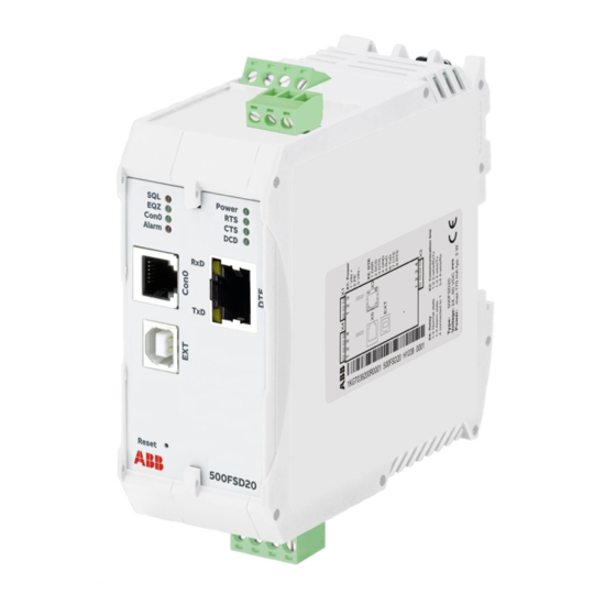
Page 20: Compact Device 500Fsd20
Compact device 500FSD20 Device description Power supply input (X1) Operating voltage 24...60 V DC -15%...+20% Power consumption (typical) 2.4 W Current demand (peak) 160 mA Ordering information 500FSD11 R0001 1KGT019301R0001 Compact device 500FSD20 4.3.1 Overview 500FSD20 RxD DCD CTS NF2a (M1) (M2) NF2b... -
Page 21: Device Data 500Fsd20
Device description Compact device 500FSD20 Connectors Type "Power connector (X1)", page 23 "Serial interface to DTE (X2)", page 24 "Interface to transmission line (X3)", page 25 "Alarm relay (X4)", page 26 "Serial interface for configuration (Con0)", page 27 "Extension interface (EXT)", page 27 4.3.3 Device data 500FSD20 The interface data can be found in Chapter 4.5, "Connections". - Page 22 General data Device description General standards • IEC 60255-21-2 class 1 • IEC 60255-21-3 class 1 • EN 50125-3 class T1 and T2 Electromagnetic compatibility (EMC) tested • IEC 61000-6-1 according to • IEC 61000-6-2 • IEC 61000-6-3 • IEC 61000-6-4 •...
-
Page 23: Connections
Device description Connections Environmental conditions - mechanical 100 m/s², 16 ms 1000 shocks per direction IEC 60255-21-2 class 1 Emission test Radiated emissions - enclosure ports (30 Mhz EN 55022/ CISPR 22 class A to 1 GHz), CISPR 16-2-3/ EN 55016-2-3 Immunity test Electrostatic discharge, IEC 61000-4-2 8 kV air / 6 kV contact (level 3), criterion A... -
Page 24: Serial Interface To Dte (X2)
Connections Device description Power supply input (X1) Ripple on DC power supply, IEC 61000-4-17 10% Un Conducted emissions - asymetrical DC ports, EN 55032/ CISPR 32 class B common mode (0.15 MHz to 30 MHz), CISPR 16-2-1/ EN 55016-2-1 Pin allocation power supply (X1) Signal 24-60 V DC Shield connected to functional earth... -
Page 25: Interface To Transmission Line (X3)
Device description Connections Pin allocation serial interface DTE (RJ-45) RS-232-D Signal V.24 Signal V.28 Direction DSR M1 output DCD M5 output DTR S1 108.2 input RxD C2 output TxD D1 input CTS M2 output RTS S2 input 4.5.3 Interface to transmission line (X3) In two-wire mode X3-1 and X3-2 form terminal NF1 which is used for transmission and reception. -
Page 26: Alarm Relay (X4)
Connections Device description Pin allocation transmission line interface (X3) Signal NF1a NF1b NF2a NF2b 4.5.4 Alarm relay (X4) The EDS500 devices are equipped with a potential free alarm output (relay with isolated switchover contact). This output corresponds to a device alarm and is activated when the device looses the power supply or the alarm LED is constantly on (see Chapter 4.6, "Display elements"). -
Page 27: Serial Interface For Configuration (Con0)
Device description Connections W A R N I N G The device shall be powered off while accessing any of the connectors X1 (power connector) or X4 (alarm relay). Any other connectors (e.g. RS-232 or 4-wire/2-wire communication port/X3) are hot-pluggable while the device is operating. W A R N I N G No plug shall be freely accessible in normal operation due to safety reasons. -
Page 28: Display Elements
Display elements Device description Display elements Description Function Power Voltage Supply Device is without power supply green Power supply switched on Request to send DTE does not send green DTE requests to send via the modem Clear to send CTS inactive green The CTS is switched on when the carrier is being estab-... -
Page 29: Maintenance
Device description Maintenance A D V I C E AllThe established communication connections will be lost temporarily during restart. Maintenance EDS500 series devices do not require any maintenance. There are no wear and tear parts. There are no moving parts. Thermal convection cools the device. - Page 30 Maintenance Device description 1KGT151042 V000 1...
-
Page 31: Glossary
Glossary Glossary Alternating Current CCITT International Telegraph and Telephone Consultative Commit- tee (Comité Consultatif International Téléphonique et Télé- graphique) Clear to Send Direct Current Data Carrier Detect Data Set Ready Data Terminal Equipment Data Terminal Ready ETSI European Telecommunications Standards Institute Frequency-shift keying Ground International Electrotechnical Commission... - Page 32 Glossary 1KGT151042 V000 1...
- Page 33 1KGT151042 V000 1...
- Page 34 Hitachi ABB Power Grids reserves all rights in particular copyrights and other intellectual property rights. Any reproduction, disclosure to third parties or utilization of its contents - in whole or in part - is not permitted without the prior written consent of Hitachi ABB Power Grids.