ABB EDS500 Series Operating Instruction
Managed ethernet switch
Hide thumbs
Also See for EDS500 Series:
- Function manual (156 pages) ,
- Manual (46 pages) ,
- Operating instruction (7 pages)
Advertisement
Quick Links
Operating instruction
Operating instruction
Managed Ethernet switch 500NMD11
Managed Ethernet switch 500NMD11
EDS500 series - Ethernet & DSL switches
EDS500 series - Ethernet & DSL switches
Application, characteristics and technical data have to
be taken from the hardware data sheet:
500NMD11 Data sheet 1KGT 150 792
Operation
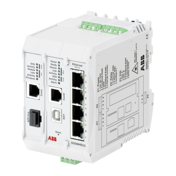
The compact modem 500NMD11 has one SHDSL wide
area interface, one optical interface as SFP plug-in
and four Ethernet interfaces. There are two serial
interfaces for configuration or process interface (e.g.
to connect telecontrol units). A configurable alarm
relais and an extension interface (e.g. to use the
configuration stick) complete the device.
Figure 1: 500NMD11 Block diagram
Connections
Ethernet interfaces (Port1 - Port4)
Every Ethernet interface detects automatically
whether the connected counterpart works as
transmission or network termination device. This way
both normal and crossover cables can be used (MDI/
MDI-X).
The Ethernet interface can operate at transmission
rates of 10 or 100 Mbps, depending on the connected
devices in half duplex or full duplex mode. The
operation mode is detected and set automatically
by the EDS500 devices. A manual configuration is
possible.
RS-232/
2-wire Cu
RS-485
DSL 1
Console0
Tunnel
SHDSL-Interface
Intelligent Switch
(Layer 2 or 3)
1
2
3
4
5
WAN
local LAN
8
RS-232
SFP Interfaces (Fo1)
Console1
All SFP interfaces are designed according to Small
CFG
CFG
Tunnel
Form-Factor Pluggable (INF-8074i).
Configuration
and Monitoring
Only transceivers up to laser class 1 according to
EN 60825-1 are allowed to be used for the SFP
interfaces.
Any warranty claims can only extend to SFPs
delivered by ABB.
DSL interface (X3)
The data transmission method SHDSL "Single-pair
High-speed Digital Subscriber Line" has been specified
by the International Telecommunications Union
(ITU recommendation G.991.2) and represents a
modern, high performance, comfortable and secure
communication method. SHDSL works with data rates
from 192 kbps up to 5.696 Mbps on a copper pair in
full duplex mode. EDS500 devices additionally use
a proprietary extension of the SHDSL standard and
can reach data rates of up to 15.000 Mbps. Wires with
a diameter of 0.8 mm give a range of 13 km at 2.048
Mbps or 25 km at 192 kbps.
Pin allocation Ethernet interface (RJ-45)
Pin
assigned as data
transmission
device (MDI)
1
Tx+
2
Tx-
3
Rx+
1
4
n.c.
5
n.c.
6
Rx-
7
n.c.
8
n.c.
W A R N I N G
A D V I C E
assigned as
network termi-
nation device
(MDI-X)
Rx+
Rx-
Tx+
n.c.
n.c.
Tx-
n.c.
n.c.
Advertisement

Related Manuals for ABB EDS500 Series


Summary of Contents for ABB EDS500 Series
- Page 1 Operating instruction Operating instruction Managed Ethernet switch 500NMD11 Managed Ethernet switch 500NMD11 EDS500 series - Ethernet & DSL switches EDS500 series - Ethernet & DSL switches Application, characteristics and technical data have to Pin allocation Ethernet interface (RJ-45) be taken from the hardware data sheet:...
- Page 2 Pin allocation DSL interface (X3) Pin allocation serial interface RS-485 full duplex (RJ-12) Signal RS-485 full duplex / 4-wire Line A (DSL A) Signal Direction Line B (DSL B) Functional earthing and cable shield B (-) Input B (-) Output A D V I C E A (+) Input...
-
Page 3: Description Function
Pin allocation alarm output (X2) Description Function Signal Ethernet No connection connection 1 & 2 Normal state green Link established 1 & 3 Alarm state flash Activity (send or receive) Common contact (connected to 1) Ethernet Data rate 10 Mbps data rate orange Data rate 100 W A R N I N G... - Page 4 The command line interface m a s t e r > and < s e t i n t e r f a c e { d s l 1 | d s l 2 } m o d e s l a v e > . The command line of the 500NMD11 is similar to the (DOS) command line known from the PC.
- Page 5 < s e t s w i t c h p o r t 2 t r u n k - v l a n 1 0 > , the command < s h o w i n t e r f a c e { d s l 1 | •...
- Page 6 A D V I C E W A R N I N G During a firmware update the power supply An easy to access manual interrupter has to be must not be interrupted or a reboot must not installed into the power feed of the modem to be be triggered as this could leave the device in an able to disconnect the modem from the power inoperable state.
- Page 7 Tel. +49 621 381-3000 particulars shall prevail. ABB AG does not or in parts – is forbidden without prior written accept any responsibility whatsoever consent of ABB AG. Copyright© 2019 ABB AG for potential errors or possible lack of All rights reserved www.abb.com/remote-terminal-units...