
Related Manuals for Mitsubishi Electric MELSEC QJ71PB92D


Summary of Contents for Mitsubishi Electric MELSEC QJ71PB92D
- Page 1 MITSUBISHI ELECTRIC MELSEC System Q Programmable Logic Controllers User’s Manual PROFIBUS-DP Interface Modules QJ71PB92D Art. no.: 136267 INDUSTRIAL AUTOMATION MITSUBISHI ELECTRIC 07 05 2001 SH (NA)-080127-B...
-
Page 2: Safety Precautions
• SAFETY PRECAUTIONS • (Read these precautions before using.) Before using this product, please read this manual and the relevant manuals introduced in this manual carefully and pay full attention to safety to handle the product correctly. The instructions given in this manual are concerned with this product. For the safety instructions of the programmable controller system, please read the CPU module user's manual. - Page 3 [INSTALLATION PRECAUTIONS] CAUTION • Use the PLC in an environment that meets the general specifications contained in the CPU user's manual. Using this PLC in an environment outside the range of the general specifications may cause electric shock, fire, malfunction, and damage to or deterioration of the product. •...
- Page 4 [STARTING AND MAINTENANCE PRECAUTIONS] DANGER • Switch all phases of the external power supply off before cleaning. Not doing so could cause electric shock. CAUTION • Never disassemble or modify the module. This may cause breakdowns, malfunctioning, injury and/or fire. •...
-
Page 5: Revisions
This manual confers no industrial property rights or any rights of any other kind, nor does it confer any patent licenses. Mitsubishi Electric Corporation cannot be held responsible for any problems involving industrial property rights which may occur as a result of using the contents noted in this manual. -
Page 6: Table Of Contents
INTRODUCTION Thank you for purchasing the Mitsubishi Programmable Controller MELSEC-Q Series. Before using the equipment, plese read this manual carefully to develop full familiarity with the functions and performance of the graphic operation terminal you have purchased, so as to ensure correct use. Please forward a copy of this manual to the end user. - Page 7 4.2 Operation Mode ............................4-11 4.2.1 Normal service mode (MODE 0) ..................... 4-12 4.2.2 Extended service mode (MODE E) ....................4-13 5. PROCEDURES BEFORE SYSTEM OPERATION 5- 1 to 5- 12 5.1 Procedures before Operation ......................... 5- 1 5.1.1 Parameter setting procedure ......................5- 2 5.2 Installation ...............................
-
Page 8: About Manuals
MELSoft GX Configurator-DP 4.00 Configuration System for Open Networks IB-65778 Software Manual Inquiries can be made to : MITSUBISHI ELECTRIC EUROPE Factory Automation Gothaer Strasse 8 D-40880 Ratingen Germany Phone : +49(21 02)486-0 Fax : +49(21 02)486-717 A - 7... -
Page 9: Conformation To The Emc Directive And Low Voltage Instruction
Conformation to the EMC Directive and Low Voltage Instruction For details on making Mitsubishi PLC conform to the EMC directive and low voltage instruction when installing it in your product, please see Chapter 3, "EMC Directive and Low Voltage Instruction" of the PLC CPU User’s Manual (Hardware). The CE logo is printed on the rating plate on the main body of the PLC that conforms to the EMC directive and low voltage instruction. -
Page 10: Overview
1 OVERVIEW MELSEC-Q 1. OVERVIEW This is the user's manual for the QJ71PB92D PROFIBUS-DP interface module (hereafter abbreviated as " QJ71PB92D. When explain separately, however, abbreviated as QJ71PB92D), which is used to connect a MELSEC-Q series programmable controller to a PROFIBUS-DP network. The QJ71PB92D operates as a master station (class 1) in the PROFIBUS-DP network. -
Page 11: Qj71Pb92D Features
1 OVERVIEW MELSEC-Q 1.2 QJ71PB92D Features (1) Operates as a PROFIBUS-DP master (class 1) station. (2) Makes possible the exchange of input and output data to and from the slave station without the need to be aware of the PROFIBUS-DP protocol by using I/O signals X/Y and the buffer memory. -
Page 12: System Configuration
2 SYSTEM CONFIGURATION MELSEC-Q 2. SYSTEM CONFIGURATION This chapter describes the system configuration of QJ71PB92D. 2.1 Adaptive System The modules and software programs used on QJ71PB92D are shown below. (1) Adaptive CPU modules ApplicableIn Inapplicable Q02CPU* Q00JCPU Q02HCPU* Q00CPU Q06HCPU* Q01CPU Q12HCPU* Q25HCPU*... -
Page 13: When Used In Multi-Cpu System
2 SYSTEM CONFIGURATION MELSEC-Q 2.2 When Used in Multi-CPU System When using QJ71PB92D in the multi-CPU system, take care of the following. The control of QJ71PB92D is performed by any CPU. A total of merely 64 sheets of QJ71PB92D is installed for each system. It is not the mountable number of sheets for each controlled CPU, but the total number of sheets controlled by all CPUs. -
Page 14: Precautions For Configuring A System
2 SYSTEM CONFIGURATION MELSEC-Q 2.3 Precautions for Configuring a System (1) The following configuration software programs cannot be used on QJ71PB92D. SW05F-PROFIMAP MELSEC-PROFIMAP 1.0 MELSEC-PROFIMAP 2.0 MELSEC-PROFIMAP 3.0 (2) The separation prevention function can be used only on those products having QCPU (Q mode) with serial No. -
Page 15: Confirmation Of Serial No
2 SYSTEM CONFIGURATION MELSEC-Q 2.4 Confirmation of Serial No. The serial Nos. of QCPUs (Q mode) capable of using the separation prevention function of QJ71PB92D and their confirmation method are shown below. (1) Serial Nos. of QCPUs (Q mode) capable of using the separation prevention function Products with serial No. -
Page 16: Specifications
3 SPECIFICATIONS MELSEC-Q 3. SPECIFICATIONS This section explains the QJ71PB92D the general specifications, performance specifications, and transmission specifications. For the general specifications of the QJ71PB92D, refer to the user’s manual for the CPU module to be used. 3.1 Performance Specifications Item Specifications Model... -
Page 17: Network Configuration
3 SPECIFICATIONS MELSEC-Q 3.2 Network Configuration 3.2.1 Basic configuration 1) Equipment types Class 1 master GX Configurator-DP Slave Repeater 2) Number of units that can be connected to the entire network (when repeaters are used) Master+slave ≤ 126 units 3) Number that can be connected for 1 segment Master+slave+repeaters ≤... -
Page 18: Applicable Configuration
3 SPECIFICATIONS MELSEC-Q 3.2.2 Applicable configuration 1) When 1 master (class 1) station is connected Master (class 1) QJ71PB92D CPU mlodule GX Configurator-DP Slave Slave Slave Station No. 1 Station No. 2 Station No. 31 A maximum of 32 stations can be connected to 1 segment. 2) When 1 master (class 1) station and 1 repeater are connected Master (class 1) QJ71PB92D... - Page 19 3 SPECIFICATIONS MELSEC-Q 3) When 1 master (class 1) station and 3 repeaters are connected Master (class 1) QJ71PB92D CPU module GX Configurator-DP Repeater Slave Slave Slave Station No. 1 Station No. 2 Station No. 18 Repeater Slave Slave Station No. 19 Station No.
- Page 20 3 SPECIFICATIONS MELSEC-Q 4) When 126 master (class 1) and slave stations are connected (When 60 or more slaves are connected) 2nd master 1st master (class 1) (class 1) 3rd master CPU module (class 1) Repeater Slave Slave Slave Slave Station No.
- Page 21 3 SPECIFICATIONS MELSEC-Q POINT In configurations that use multiple master stations (multimaster configuration), when reconnecting a cable after disconnecting a PROFIBUS cable for 1 master that is exchanging data at a low baud rate, the communications of the master for which the cable is not disconnected could stop and the slave output could be turned off.
-
Page 22: Number Of Connectable Slaves
3 SPECIFICATIONS MELSEC-Q 3.2.3 Number of connectable slaves Please calculate the number of the slave which can be connected under the following (1) and (2) conditions. (1) The maximum data length of the slave station error information that the QJ71PB92D can receive varies with the minimum station number and maximum station number of the slave stations set in the parameters, and can be calculated using the following expression. - Page 23 3 SPECIFICATIONS MELSEC-Q The number of parameter blocks for each station is decided by the parameter size of the station as follows. Parameter size Number of block 246 bytes or less 1 block 247 to 480 bytes 4 blocks 481 to 720 bytes 5 blocks 721 to 762 bytes 6 blocks...
-
Page 24: I/O Signal
3 SPECIFICATIONS MELSEC-Q 3.3 I/O Signal 3.3.1 I/O signal list The I/O signal configuration used in the QJ71PB92D and the data communications with the PLC CPU are described below. Signal direction: QJ71PB92D PLC CPU Signal direction: PLC CPU QJ71PB92D Device No. Description Device No. -
Page 25: I/O Signal Detail Description
3 SPECIFICATIONS MELSEC-Q 3.3.2 I/O signal detail description (1) Exchange start request signal (Y00), exchange start end signal (X00) (a) After the exchange start request signal (Y00) is turned on by the sequence program the exchange start end signal (X00) is turned on when cyclic exchange starts. - Page 26 3 SPECIFICATIONS MELSEC-Q (3) Communication trouble area clear request (Y02), communication trouble area clear end (X02) (a) The communication trouble area clear request (Y02) is turned on by the sequence program when all of the communication trouble areas and extension trouble areas are cleared. (b) The communication trouble clear end signal (X02) is turned on after all of the communication trouble area and extension trouble areas are cleared by turning on the communication trouble area clear request signal (Y02).
- Page 27 3 SPECIFICATIONS MELSEC-Q (5) Global control error end signal (X05) (a) If global control is requested when exchange start (X00) is not on then global control error end (X05) and the global control service end signal (X04) will turn on at the same time. (b) The slave I/O is not held/deleted when the global control error end signal (X05) is on.
- Page 28 3 SPECIFICATIONS MELSEC-Q (8) Communication READY signal (X1B) (a) This is turned on when the station enters the exchange start possible state after the QJ71PB92D has started up and the module READY signal (X1D) has turned on. (Only during the normal service mode (MODE O) and extended service mode (MODE E).) (b) This turns off when a exchange continuation impossible error occurs.
-
Page 29: Buffer Memory List
3 SPECIFICATIONS MELSEC-Q 3.4 Buffer Memory List 3.4.1 Buffer memory/configuration The configuration of the buffer memory used to receive and send data with the QJ71PB92D and the PLC CPU is described below. Buffer memory address Area name Description decimal (Hexadecimal) Input area This is the area that stores the input data from the slave. -
Page 30: Buffer Memory Detailed Description
3 SPECIFICATIONS MELSEC-Q 3.4.2 Buffer memory detailed description (1) INPUT area (Buffer memory address: 0 (0 ) to 959 (3BF Either the normal service mode (Mode 0) or extended service mode (Mode E) can be selected using GX Configurator-DP. (a) Normal service mode (MODE 0) This is the area that stores the input data from the slave station. - Page 31 3 SPECIFICATIONS MELSEC-Q (b) Extended service mode (MODE E) This is the area that stores the input data from the slave station. In this area, the data length (in byte units) for each station is assigned in variable length according to the parameter file set in the GX Configrator-DP. The data length can be set in the range of 0 to 244 bytes.
- Page 32 3 SPECIFICATIONS MELSEC-Q (2) OUTPUT area (Buffer memory address: 960 (3C0 ) to 1919 (77F Either the normal service mode (Mode 0) or extended service mode (Mode E) can be selected using GX Configurator-DP. (a) Normal service mode (MODE 0) This is the area that stores the output data to the slave station.
- Page 33 3 SPECIFICATIONS MELSEC-Q (b) Extended service mode (MODE E) This is the area that stores the output data to the slave station. In this area, the data length (in byte units) for each station is assigned in variable length according to the parameter file set in the GX Configrator-DP. The data length can be set in the range of 0 to 244 bytes.
- Page 34 3 SPECIFICATIONS MELSEC-Q (3) Address information area (Buffer memory address: 1920 (780 ) to 2039 (7F7 This area shows the station address, input byte length, and output byte length for each slave station. This allocation is set by the GX Configrator-DP. The station addresses for the 1st through the 60th stations are stored in the order of registration in the GX Configrator-DP.
- Page 35 3 SPECIFICATIONS MELSEC-Q (4) Example address information area, INPUT area, and OUTPUT area The QJ71PB92D reads the slave station address and I/O byte length set by the parameter file which is set by the GX Configrator-DP and stores these in the buffer memory address information area.
- Page 36 3 SPECIFICATIONS MELSEC-Q (5) Communication trouble area (Buffer memory address: 2040 (7F8 to 2079 (81F When some kind of trouble occurs during communication the QJ71PB92D stores the contents of the trouble in this area. Fixed type or ring type can be selected for this area by turning the communication trouble area type selection (Y03) on or off (refer to Section 3.3.2 (11)).
- Page 37 , 1300 above. 1211 , 1300 2) Otherwise errors. An unexpected error has occurred. For 2) Contact the nearest Mitsubishi Electric branch office or dealer. : Exchange stops after the error occurs. : Exchange continues. 3 - 22 3 - 22...
- Page 38 3 SPECIFICATIONS MELSEC-Q (c) When the trouble code = 0200 For a slave trouble information occurrence (error code = 0200 ), the slave trouble information is stored in the detailed data. The communication trouble area configuration for this case is shown below. In addition, the expansion communication trouble information is stored in buffer memory 2096 to 2110 for only the latest trouble information of the error code = 0200 trouble...
- Page 39 3 SPECIFICATIONS MELSEC-Q (6) Expansion communication trouble area (Buffer memory address: 2096 (830 ) to 2110 (83E This area shows the latest expansion trouble information for only one of the latest expansion trouble information in the error code 0200 error information stored in buffer memory 2040 to 2079 communication error area (Refer to Section 3.4.2 (5)).
- Page 40 3 SPECIFICATIONS MELSEC-Q (b) Buffer memory 2097 (831 Only bit 7 is valid. Other bit is fixed in 0. Bit 7 is turned on when the slave sends expansion trouble information that is 27 bytes or more. Bit position 0 fixed 0 fixed (c) Buffer memory 2098 to 2110 (832 to 83E...
- Page 41 3 SPECIFICATIONS MELSEC-Q 2) Identifier related trouble information For module type slave stations, this stores as bit information whether or not a module is outputting an error. The identifier related trouble information can be divided into header and trouble information. This area stores a 2 bit value that is the identifier related trouble information in the header, including the header (1 byte), and the device related trouble information for this area.
- Page 42 3 SPECIFICATIONS MELSEC-Q 3) Channel related trouble information When a module type slave station, this area stores the trouble information for each module that is outputting an error. This area does not have a header and stores this information at the end of the identifier related trouble information.
- Page 43 3 SPECIFICATIONS MELSEC-Q 4) Identifier No., channel No. The slave identifier No. and channel No. are discussed below. The identifier No. is the No. that is attached from the header of each slave module. Each module can have multiple channels. Refer to the each slave specifications regarding to the channel numbering method.
- Page 44 3 SPECIFICATIONS MELSEC-Q (7) Example expansion communication trouble area Buffer memory address demical (Hexadecimal) Expansion communication trouble information length (byte length) 2096(830 Header (length 4) 2098(832 Device : Vendor independent trouble information Header (length 4) Identifier Identifier Nos. 0 and 2 have trouble information. Identifier No.0 and Channel channel No.
- Page 45 3 SPECIFICATIONS MELSEC-Q (8) Slave trouble information cancel area (Buffer memory address: 2080 (820 This stores the value that masks the slave trouble information (error code = 0200 detailed data 2). Even if the slave trouble information corresponding to this area bit occurs the slave trouble information detection signal (X01) and RSP.ERR LED do not turn on.
- Page 46 3 SPECIFICATIONS MELSEC-Q (9) Global control area (Buffer memory address: 2081 (821 The buffer memory (2081(821 )) value and corresponding command table are shown below. Value Command Description position (valid/invalid) 8 to 15 Group 1 to 8 selection Bits 8 to 15 correspond respectively to groups 1 to 8 and shows that the bit value is transmitted by the global control command to the 1 group (refer below).
- Page 47 3 SPECIFICATIONS MELSEC-Q (10) Trouble no information time setting area (Buffer memory address: 2084 (824 Set the time at seconds unit, which does not inform the communication trouble after the exchange start. Default value is 20 seconds so the communication trouble is not informed for 20 seconds after the exchange start.
- Page 48 3 SPECIFICATIONS MELSEC-Q (12) I/O start address area (Extended service mode (MODE E) only) (Buffer memory address: 2128 (850 ) to 2247 (8C7 This area stores the start addresses of I/O areas for each slave station. Buffer memory This area is used while in the extended service mode address demical (MODE E) only.
- Page 49 3 SPECIFICATIONS MELSEC-Q (13) Current operation mode area(Buffer memory address: 2254 (8CF This area stores the value which indicates the operation mode of the QJ71PB92D when it has started up. Stored Value Detail 0000 Normal service mode (MODE 0) Where switched temporarily (not registered 0001 Parameter setting mode (MODE 1) in a Flash ROM) using GX Configurator-DP...
- Page 50 3 SPECIFICATIONS MELSEC-Q (16) Local station address display area (Buffer memory address: 2557 (8D1 Used to store the number of the local station. The storage area is 0 to 125. (17) Self-diagnosis status code area (Buffer memory address: 2558 (8D2 Used to store the test status of the offline test using codes.
-
Page 51: Functions
4 FUNCTIONS MELSEC-Q 4. FUNCTIONS 4.1 Functions for Exchanging with Slaves The main function in the QJ71PB92D is for exchanging I/O data with slave stations connected to the PROFIBUS-DP network. The method used for this exchange is to read/write the I/O image in the buffer memory using auto refresh setting, FROM/TO instruction, or dedicated instruction. -
Page 52: Exchange Flow
4 FUNCTIONS MELSEC-Q 4.1.1 Exchange flow The I/O data exchange flow with slave station is shown below. The refresh between the CPU and QJ71PB92D and the refresh of buffer memory of QJ71PB92D are executed asynchronously with each other. Set the slave trouble information cancel area. -
Page 53: Global Control Functions
4 FUNCTIONS MELSEC-Q 4.1.2 Global control functions Global control contains the four functions of SYNC, UNSYNC, FREEZE, and UNFREEZE, which are functions that are used to maintain/cancel slave I/O for which multicast communication is conducted at the same time. The slaves that execute the global control function are those located in one or more groups of the eight groups. - Page 54 4 FUNCTIONS MELSEC-Q (2) Service FREEZE, UNFREEZE Master (FREEZE transmission to group 3) Input data FREEZE (Group 8) (Group 3) (Group 3) (Group 3) Slave 1 Slave 2 Slave n Slave 3 Input image memory: The data is always refreshed by polling. <during FREEZE cancel/default>The actual input is input to the input memory unchanged (normal condition) <during FREEZE execute>The actual input is input once into the input image memory at the FREEZE...
- Page 55 4 FUNCTIONS MELSEC-Q (4) Procedure for issuing a global service. Sequence program QJ71PB92D Slave TO global control area Turn on the global control request signal (Y04). Turn on the global control end signal (X04). Global control service Time 4 - 5 4 - 5...
-
Page 56: Word Data Swap Function
4 FUNCTIONS MELSEC-Q 4.1.3 Word data swap function This is the function to exchange (swap) the upper and lower bytes of the I/O data stored in the buffer memories of the CPU and QJ71PB92D. For the PROFIBUS-DP and MELSEC series, the function is used to input and output word data into and from the slave because the upper and lower bytes are reversed to each other in the processing of the word data. - Page 57 4 FUNCTIONS MELSEC-Q Slave station Examples of data transmission (for input) Nonexecution of swap (Initial setting) QJ71PB92D Slave station Buffer memory X0 = 1 b8 b7 X8 X7 X7 = 1 X8 = 0 Upper and lower bytes XF = 0 are reversed to each other.
-
Page 58: I/O Data Separation Prevention Function
4 FUNCTIONS MELSEC-Q 4.1.4 I/O data separation prevention function The I/O data separation prevention function is a function to prevent the I/O data of the PLC CPU from being unmatched with the I/O data of the slave station. (1) I/O data separation prevention function (a) The separation of I/O data occurs when the buffer memory is also read from/written to the PLC CPU during the data transmission between the buffer memory of QJ71PB92D and the slave station. - Page 59 4 FUNCTIONS MELSEC-Q (2) Separation prevention by auto refresh setting When a data transmission between the buffer memory of QJ71PB92D and the PLC CPU is performed by auto refresh setting, the separation is selected to function the separation prevention. To activate the separation prevention function, two methods are available: a method to select the Separation Prevention in setting the I/O data batch auto refresh and a method to select it in setting the auto refresh for each station.
- Page 60 4 FUNCTIONS MELSEC-Q (3) Separation prevention by dedicated instruction The separation prevention function is executed using the BBLKRD instruction (read) and BBLKWR (write) which are the dedicated instructions for reading/writing of the buffer memory from and to QJ71PB92D. When the writing/reading of the buffer memory are executed using the FROM/TO instruction, the separation prevention function cannot be used.
-
Page 61: Operation Mode
4 FUNCTIONS MELSEC-Q 4.2 Operation Mode QJ71PB92D has four operation modes: Normal service mode (MODE 0), Extended service mode (MODE E), Parameter setting mode (MODE 1), and Self-diagnosis mode (MODE 2). The operating modes are set using the GX Configurator-DP. Each of these modes is explained as follows. -
Page 62: Normal Service Mode (Mode 0)
4 FUNCTIONS MELSEC-Q 4.2.1 Normal service mode (MODE 0) This is the mode for communicating with the slave station by allocating 32 bytes (16 words) of I/O area of the QJ71PB92D buffer memory to each slave station. Because the I/O area size of each slave station is fixed, the buffer memory address is easier to understand, and the size need not be set to the parameters for each slave station. -
Page 63: Extended Service Mode (Mode E)
4 FUNCTIONS MELSEC-Q 4.2.2 Extended service mode (MODE E) This is the mode for communicating with the slave station by allocating any I/O area of the QJ71PB92D buffer memory to each slave station. Because the I/O area size can be set for each slave station, an empty space is not produced in the buffer memory of QJ71PB92D. -
Page 64: Procedures Before System Operation
The QJ71PB92D starts self-diagnosis Is there an error with self-diagnosis? This is a hardware problem, so contact the nearest Mitsubishi Electric dealer and explain the symptoms to the dealer Set parameters using GX Configurator-DP Is the automatic refresh used? Reset the PLC CPU... -
Page 65: Parameter Setting Procedure
5 PROCEDURES BEFORE SYSTEM OPERATION MELSEC-Q 5.1.1 Parameter setting procedure The procedure for setting the QJ71PB92D parameters is described below. (1) Start GX Configurator-DP, and select the module type and mode from the [file]- [New] menu. (2) In the [Setup]-[GSD Device-Database] menu, register the GSD file (DDB file) for each slave. - Page 66 5 PROCEDURES BEFORE SYSTEM OPERATION MELSEC-Q The parameter items set in QJ71PB92D using GX Configurator-DP are shown below. (1) Master Parameter Parameter Range Meaning Name — States that the QJ71PB92D is a master. 9.6 kbps Transfer rate for the communication. Define a baud rate Baud Rate to12.000 Mbps that is supported by all slaves.
- Page 67 5 PROCEDURES BEFORE SYSTEM OPERATION MELSEC-Q (2) Bus Parameter Usually, the bus parameters need not be changed. When changing these parameters, understand the PROFIBUS-DP standards beforehand. Parameter Meaning Range Remark Baud rate Transfer rate see selection Must be supported by all slaves T_sl Slot time...
- Page 68 5 PROCEDURES BEFORE SYSTEM OPERATION MELSEC-Q (3) Slave Parameter parameter Range Meaning Name — The name of the slave can be defined. FDL address 0 to 126 This parameter is used to define the station address of the slave. Click on the white box if you want to use the watchdog timer for this device.
-
Page 69: Installation
5 PROCEDURES BEFORE SYSTEM OPERATION MELSEC-Q 5.2 Installation The following section explains the precautions when handling the QJ71PB92D, from the time they are unpacked until they are installed. For more details on the module installation, see the user's manual for the PLC CPU used. -
Page 70: Part Names And Settings
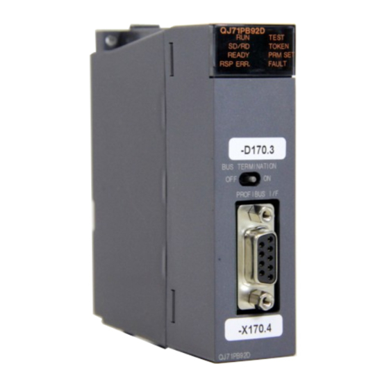
5 PROCEDURES BEFORE SYSTEM OPERATION MELSEC-Q 5.3 Part Names and Settings Following is an explanation of the QJ71PB92D part names and settings. QJ71PB92D TEST SD/RD TOKEN READY PRM SET RPS ERR. FAULT BUS TERMINATION PROFIBUS I/F QJ71PB92D Name Description Remark Displays the QJ71PB92D status. - Page 71 5 PROCEDURES BEFORE SYSTEM OPERATION MELSEC-Q Name Description Remark PRM.SET Turns on when the operation is in the Parameter setting mode (MODE 1)(PARAMETER.SET). If this is lit when the operation is in the Normal service mode (MODE O) or Extended service mode (MODE E), the parameters will not be written.
-
Page 72: Execution Method For Self-Diagnosis
5 PROCEDURES BEFORE SYSTEM OPERATION MELSEC-Q 5.4 Execution Method for Self-diagnosis This section describes the procedure for self-diagnosis, status during self-diagnosis, and results after self-diagnosis. (1) Procedure for self-diagnosis The procedure for self-diagnosis is as follows. 1) Set QJ71PB92D to the Self-diagnosis mode (MODE 2) using GX Configurator- DP or operation mode change request signal (Y11). -
Page 73: Wiring
5 PROCEDURES BEFORE SYSTEM OPERATION MELSEC-Q 5.5 Wiring 5.5.1 PROFIBUS cable wiring This section explains the wiring to PROFIBUS connector for the QJ71PB92D (1) Pin assignments for the connector Pin No. Symbol Name Application SHIELD Shield, Protective Ground Reserved for Power B/B’... -
Page 74: Precautions Against Wiring
5 PROCEDURES BEFORE SYSTEM OPERATION MELSEC-Q 5.5.3 Precautions against wiring As one of the requirements to give full play to QJ71PB92D’s functions and make up the system with high reliability, it is necessary to have an external wiring unsusceptible to an influence of noise. Precautions against external wiring of QJ71PB92D is described below. -
Page 75: Maintenance And Inspection
5 PROCEDURES BEFORE SYSTEM OPERATION MELSEC-Q 5.6 Maintenance and Inspection For the QJ71PB92D, eliminate the check of cable connection and looseness and do not include it as an inspection item. Otherwise, follow the inspection item instructions in the PLC CPU User’s Manual to always use the system in good condition. DANGER Switch all phases of the external power supply off before cleaning. -
Page 76: Communication Time
6 COMMUNICATION TIME MELSEC-Q 6. COMMUNICATION TIME 6.1 Bus Cycle Time (1) Bus cycle time when there is one master station An explanation of the bus cycle time when there is one master station is given in the following diagram. The following diagram (Fig. 6.1) shows an example for when there are 3 slave stations. - Page 77 6 COMMUNICATION TIME MELSEC-Q The master bus cycle time Bc can be calculated as: Number of the slave stations Bc = Max (MSI, (Pt (i) + Tsdi (M)) + Lr i = 1 However, The largest of A and B = Max (A, B) Pt (i) = No.i station polling time = Treq(i) + Max Tsdr (i) + Tres (i) Treq (i) No.i station request transmission time = ((number of output bytes to No.i station + 9)
- Page 78 6 COMMUNICATION TIME MELSEC-Q (2) Bus cycle time when there are multiple master stations Following is an explanation of the bus cycle time when multiple masters are connected to the same network. The following diagram (Fig. 6.2) shows when 2 masters are connected to the same network.
-
Page 79: Transmission Delay Time
6 COMMUNICATION TIME MELSEC-Q 6.2 Transmission Delay Time The transmission delay time for input and output data is as follows. (1) Without separation prevention function A transmission delay time when I/O data is read/written using the automatic refresh setting (without separation prevention function) or FROM/TO instruction. (a) Output delay Transmission delay time Normal value... -
Page 80: Programming
7 PROGRAMMING MELSEC-Q 7. PROGRAMMING The following shows the program examples used to execute the global control and execute the separation prevention function using the dedicated instruction during the communication in the Normal service mode (MODE 0) and Extended service mode (MODE E). - Page 81 7 PROGRAMMING MELSEC-Q (b) In the slave parameters, set the devices and head numbers used for automatic refresh. Make settings using [Slave Parameter Settings]: Addresses in MELSEC CPU Memory.You need not set the numbers of refresh points since they are automatically calculated by GX Configurator-DP from the slave parameters.
- Page 82 7 PROGRAMMING MELSEC-Q (d) Before starting the communication with the PLC an entry in the network configuration atabase must be selected. Right-click on the project window to open the context menu and select Select Network to open the Select Network Index dialog.
- Page 83 7 PROGRAMMING MELSEC-Q (f) The information obtained from the CPU contains slot, head address, the actual IO length of the module as well as a preset IO length and module name. (g) You have to assign a GX Configurator file to each master, for which you intend to include autorefresh settings in the IPARAM file.
- Page 84 7 PROGRAMMING MELSEC-Q (h) A file browser dialog opens where you can select a GX Configurator-DP file to be assigned to the selected DP master. (i) Right-click on a DP master entry to select it and to open the context menu. From the context menu select Edit Settings.
- Page 85 7 PROGRAMMING MELSEC-Q (j) The autorefresh settings editor dialog box appears. Check Slave Specific Transfer. POINT You can use automatic block transfer to shorten I/O data transfer time. To use this function, set I/O devices for Block Transfer in the above dialog box. At this time, the autorefresh settings made using the slave parameters are invalid.
- Page 86 7 PROGRAMMING MELSEC-Q (2) Program example When the automatic refresh function is used, the read/write program is not required for the input/output areas. Not required if the initial setting is not changed. Initial setting Slave trouble information cancel area setting Trouble information unnotification...
- Page 87 7 PROGRAMMING MELSEC-Q Communication trouble detection signal reset Communication trouble area clear command pulse Communication trouble area clear command Change to Mode change self-diagnosis mode (MODE 2) Execution of operation mode change request Read of operation mode change results Read of present operation mode...
-
Page 88: Normal Service Mode (Mode 0) Using From/To Instruction
7 PROGRAMMING MELSEC-Q 7.2 Normal Service Mode (MODE 0) Using FROM/TO Instruction The following shows the program example used when the I/O data is read/written using the FROM/TO instruction in the Normal service mode (MODE 0). Not required if the initial setting is not changed. Initial setting Slave trouble information... - Page 89 7 PROGRAMMING MELSEC-Q Processing against communication trouble Trouble information read Trouble detection signal reset command pulse Communication trouble detection signal reset Communication trouble area clear command pulse Communication trouble area clear command Mode change Change to self-diagnosis mode (MODE 2) Execution of operation mode change request...
- Page 90 7 PROGRAMMING MELSEC-Q Read of operation mode change results Read of present operation mode 7 - 11 7 - 11...
-
Page 91: Extended Service Mode (Mode E) Using From/To Instruction
7 PROGRAMMING MELSEC-Q 7.3 Extended Service Mode (MODE E) Using FROM/TO Instruction The following shows the program example used when the I/O data is read/written using the FROM/TO instruction in the Extended service mode (MODE E). Not required if the initial setting is not changed. Initial setting Slave error information... - Page 92 7 PROGRAMMING MELSEC-Q Processing in which input data is used Output data ON/OFF program Write to output area Processing against communication trouble Trouble information read Trouble detection signal reset command pulse Communication trouble detection signal reset Communication trouble area clear command pulse Communication trouble area clear...
- Page 93 7 PROGRAMMING MELSEC-Q Mode change Change to self-diagnosis mode (MODE 2) Execution of operation mode change request Read of operation mode change results Read of present operation mode 7 - 14 7 - 14...
-
Page 94: Normal Service Mode (Mode 0) Using Dedicated Instruction
7 PROGRAMMING MELSEC-Q 7.4 Normal Service Mode (MODE 0) Using Dedicated Instruction The following shows the program example used when the I/O data is read/written using the dedicated instruction for separation prevention in the Normal service mode (MODE 0). Not required if the initial setting is not changed. Initial setting Slave error information... - Page 95 7 PROGRAMMING MELSEC-Q Output data ON/OFF program Write to output area Write in which separation is prevented Processing against communication trouble Trouble information read Trouble detection signal reset command pulse Communication trouble detection signal reset Communication trouble area clear command pulse Communication trouble area clear command...
- Page 96 7 PROGRAMMING MELSEC-Q Mode change Change to self-diagnosis mode (MODE 2) Execution of operation mode change request Read of operation mode change results Read of present operation mode 7 - 17 7 - 17...
-
Page 97: Execution Of Global Control
7 PROGRAMMING MELSEC-Q 7.5 Execution of Global Control The following shows the program example added when the global control is executed. The operation mode and I/O data read/write methods are not related to this program example. Use of global control function Transmission of SYNC command to groups 1 and 2... -
Page 98: Dedicated Instructions
8 DEDICATED INSTRUCTIONS MELSEC-Q 8. DEDICATED INSTRUCTIONS 8.1 BBLKRD Instruction Usable devices Internal device MELSECNET/H Special Index Set data (System, user) Direct J \ function File Constant register Other register module K, H Word Word U \G — — — —... -
Page 99: Bblkwr Instruction
8 DEDICATED INSTRUCTIONS MELSEC-Q 8.2 BBLKWR Instruction Usable devices Internal device MELSECNET/H Special Index Set data (System, user) Direct J \ function File Constant register Other register module K, H Word Word U \G — — — — — — —... -
Page 100: Troubleshooting
9 TROUBLESHOOTING MELSEC-Q 9. TROUBLESHOOTING For troubleshooting in the Normal service mode (MODE 0) and Extended service mode (MODE E), the causes of errors, which are located using the status of LEDs, and measures against the errors are described below. When the operation is in the Normal service mode (MODE 0) or Extended service mode (MODE E), the TEST LED indicator and PRM SET LED indicator of QJ71PB92D go off. - Page 101 9 TROUBLESHOOTING MELSEC-Q MEMO 9 - 2 9 - 2...
- Page 102 APPENDIX MELSEC-Q APPENDIX Appendix 1 Differences between QJ71PB92D and AJ71PB92D/A1SJ71PB92D The differences between QJ71PB92D of MELSEC-Q series and AJ71PB92D/A1SJ71PB92D of MELSEC-A series are shown below. The AJ71PB92D and A1SJ71PB92D to be used here are of software version C and subsequent and software version G and subsequent, respectively. For the modules of the software versions earlier than those stated above, refer to the AJ71PB92D/A1SJ71PB92D type PROFIBUS-DP interface module user's manual (SH- 3330) to confirm the difference between these software versions.
- Page 103 APPENDIX MELSEC-Q Appendix 2 Extended Trouble Information of Mitsubishi's Slaves (1) AJ95TB2-16T AJ95TB2-16T notifies device-related trouble information to the master. The information consists of seven bytes including the header (one byte) as shown below: Header Always set to 00 (Fixed to 07 Set to 1 when the external power supply COM1t is Always set to 0 not supplied...
- Page 104 APPENDIX MELSEC-Q Appendix 3 Outline Drawings QJ71PB92D TEST SD/RD TOKEN READY PRM SET RPS ERR. FAULT BUS TERMINATION PROFIBUS I/F QJ71PB92D 4.3(0.17) 2(0.08) 91(3.59) 27.4(1.08) 97.3(3.83) Unit : mm (inch) Appendix - 3 Appendix - 3...
- Page 105 APPENDIX MELSEC-Q MEMO Appendix - 4 Appendix - 4...
- Page 106 INDEX AJ71PB92D/A1SJ71PB92D ....Appendix-1 Error code..........3-20, 21 Areas Address information area ......3-17 Group...............4- 3 Communication trouble area..... 3-19 GSD file ............5- 2 Current operation mode area....3-32 GX Configurator-DP......2- 1, 5- 1, 2 Extended communication trouble area ..3-22 Global control area ........
- Page 107 WARRANTY Please confirm the following product warranty details before starting use. 1. Gratis Warranty Term and Gratis Warranty Range If any faults or defects (hereinafter "Failure") found to be the responsibility of Mitsubishi occurs during use of the product within the gratis warranty term, the product shall be repaired at no cost via the dealer or Mitsubishi Service Company. Note that if repairs are required at a site overseas, on a detached island or remote place, expenses to dispatch an engineer shall be charged for.
- Page 108 MITSUBISHI ELECTRIC HEADQUARTERS EUROPEAN REPRESENTATIVES EUROPEAN REPRESENTATIVES EUROPEAN REPRESENTATIVES MITSUBISHI ELECTRIC EUROPE GEVA AUSTRIA MITSUBISHI ELECTRIC IRELAND TURKEY Wiener Straße 89 Darülaceze Cad. No. 43 KAT: 2 EUROPE B.V. EUROPE B.V. – Irish Branch Gothaer Straße 8 A-2500 Baden Westgate Business Park...