
Related Manuals for Mitsubishi Electric QD75P1N


Summary of Contents for Mitsubishi Electric QD75P1N
- Page 1 Type QD75P/QD75D Positioning Module User's Manual -QD75P1N -QD75P2N -QD75P4N -QD75D1N -QD75D2N -QD75D4N -QD75P1 -QD75P2 -QD75P4 -QD75D1 -QD75D2 -QD75D4...
-
Page 3: Safety Precautions
SAFETY PRECAUTIONS (Read these precautions before using this product.) Before using this product, please read this manual and the relevant manuals carefully and pay full attention to safety to handle the product correctly. The precautions given in this manual are concerned with this product only. For the safety precautions of the programmable controller system, refer to the user’s manual for the CPU module used. - Page 4 [Design Precautions] CAUTION Do not bundle or adjacently lay the connection cable connected to the module external I/O signals or drive unit with the main circuit line, power line, or the load line other than that for the programmable controller. Separate these by 100mm as a guide. Failure to observe this could lead to malfunctioning caused by noise, surge, or induction.
- Page 5 [Wiring Precautions] CAUTION Use applicable solderless terminals and tighten them within the specified torque range. If any spade solderless terminal is used, it may be disconnected when the terminal screw comes loose, resulting in failure. Tighten the connector screws within the specified torque range. Undertightening can cause short circuit, fire, or malfunction.
- Page 6 [Startup/Maintenance Precautions] CAUTION Never disassemble or modify the module. Failure to observe this could lead to trouble, malfunctioning, injuries or fires. Completely turn off the externally supplied power used in the system before installing or removing the module. Failure to turn all phases OFF could lead to module trouble or malfunctioning. Do not install/remove the module to/from the base unit, or the terminal block to/from the module more than 50 times after the first use of the product.
-
Page 7: Conditions Of Use For The Product
CONDITIONS OF USE FOR THE PRODUCT (1) Mitsubishi programmable controller ("the PRODUCT") shall be used in conditions; i) where any problem, fault or failure occurring in the PRODUCT, if any, shall not lead to any major or serious accident; and ii) where the backup and fail-safe function are systematically or automatically provided outside of the PRODUCT for the case of any problem, fault or failure occurring in the PRODUCT. -
Page 8: Revisions
REVISIONS The manual number is given on the bottom left of the back cover Print Date Manual Number Revision Dec., 1999 SH (NA)-080058-A First edition Oct., 2000 SH (NA)-080058-B Addition of function version B (Overall revisions based on the Japanese Manual Version SH-080047-E) Jun., 2001 SH (NA)-080058-C... - Page 9 11.2.1, 11.3.1, 11.3.4, 11.4.1, 11.4.4, Section 12.3.2, 12.7.5, 12.7.7, Section 13.5, Section 14.3, 14.6, Section 15.3, 15.4, Appendix 1.1, Appendix 2.2, Appendix 10.1 to 10.13, Appendix 12 to 14 Additions Appendix 1.2 Addition model QD75P1N, QD75P2N, QD75P4N, QD75D1N, QD75D2N, QD75D4N A - 7...
- Page 10 This manual confers no industrial property rights or any rights of any other kind, nor does it confer any patent licenses. Mitsubishi Electric Corporation cannot be held responsible for any problems involving industrial property rights which may occur as a result of using the contents noted in this manual.
-
Page 11: Table Of Contents
INTRODUCTION Thank you for purchasing the Mitsubishi Electric general-purpose programmable controller MELSEC-Q Series. Always read through this manual, and fully comprehend the functions and performance of the Q Series programmable controller before starting use to ensure correct usage of this product. - Page 12 3. SPECIFICATIONS AND FUNCTIONS 3- 1 to 3- 30 3.1 Performance specifications ........................3- 2 3.2 List of functions ............................. 3- 6 3.2.1 QD75 control functions........................3- 6 3.2.2 QD75 main functions ........................3- 8 3.2.3 QD75 sub functions and common functions ................... 3- 10 3.2.4 Combination of QD75 main functions and sub functions ..............
- Page 13 5.2 List of parameters ........................... 5- 18 5.2.1 Basic parameters 1 .......................... 5- 18 5.2.2 Basic parameters 2 .......................... 5- 24 5.2.3 Detailed parameters 1 ........................5- 26 5.2.4 Detailed parameters 2 ........................5- 36 5.2.5 OPR basic parameters ........................5- 45 5.2.6 OPR detailed parameters ........................
- Page 14 PART 2 CONTROL DETAILS AND SETTING 8. OPR CONTROL 8- 1 to 8- 24 8.1 Outline of OPR control ........................... 8- 2 8.1.1 Two types of OPR control ....................... 8- 2 8.2 Machine OPR ............................8- 4 8.2.1 Outline of the machine OPR operation ................... 8- 4 8.2.2 Machine OPR method ........................
- Page 15 9.2.20 Position-speed switching control ....................9-123 9.2.21 Current value changing ......................... 9-130 9.2.22 NOP instruction ..........................9-135 9.2.23 JUMP instruction ........................... 9-136 9.2.24 LOOP ............................. 9-138 9.2.25 LEND ............................. 9-139 10. HIGH-LEVEL POSITIONING CONTROL 10- 1 to 10- 28 10.1 Outline of high-level positioning control .................... 10- 2 10.1.1 Data required for high-level positioning control ................
- Page 16 11.4.2 Manual pulse generator operation execution procedure ............11- 30 11.4.3 Setting the required parameters for manual pulse generator operation ........11- 31 11.4.4 Creating a program to enable/disable the manual pulse generator operation ......11- 32 12. CONTROL SUB FUNCTIONS 12- 1 to 12-110 12.1 Outline of sub functions ........................
- Page 17 Appendix 2.2 Parameter setting value entry table ..............Appendix- 10 Appendix 3 Positioning data (No. 1 to 600) List of buffer memory addresses ....... Appendix- 16 Appendix 4 Connection examples with servo amplifiers manufactured by MITSUBISHI Electric Corporation ............................Appendix- 48 Appendix 4.1 Connection example of QD75D N and MR-J3-...
- Page 18 Appendix 9.2 Comparisons with A1SD75P1-S3/A1SD75P2-S3/ A1SD75P3-S3 models ..Appendix- 57 Appendix 10 When using GX Works2 ..................... Appendix- 80 Appendix 10.1 Adding a module ....................Appendix- 81 Appendix 10.2 Setting parameters ....................Appendix- 82 Appendix 10.3 Setting auto refresh ..................... Appendix- 87 Appendix 10.4 Positioning monitor ....................
-
Page 19: About Manuals
ABOUT MANUALS The following manuals are also related to this product. In necessary, order them by quoting the details in the tables below. Related Manuals Manual Number Manual Name (Model Code) GX Configurator-QP Version 2 Operating Manual SH-080172 Data creation (such as parameters and positioning data) and operations of transferring data to modules, (13JU19) positioning monitor, and tests using GX Configurator-QP .......... -
Page 20: Compliance With Emc And Low Voltage Directives
Generic term for CPU module on which QD75 can be mounted. QD75 Generic term for positioning module QD75P1N, QD75P2N, QD75P4N, QD75D1N, QD75D2N, QD75D4N, QD75P1, QD75P2, QD75P4, QD75D1, QD75D2, and QD75D4. The module type is described to indicate a specific module. -
Page 21: Component List
The table below shows the component included in respective positioning modules: Module name Description Quantity QD75P1N QD75P1N Positioning Module(1-axis open collector output system) QD75P2N QD75P2N Positioning Module(2-axes open collector output system) QD75P4N QD75P4N Positioning Module(4-axes open collector output system) QD75D1N Positioning Module(1-axis differential driver output system) - Page 22 MEMO A - 20...
-
Page 23: Part 1 Product Specifications And Handling
PART 1 PRODUCT SPECIFICATIONS AND HANDLING PART 1 is configured for the following purposes (1) to (5). (1) To understand the outline of positioning control, and the QD75 specifications and functions (2) To carry out actual work such as installation and wiring (3) To set parameters and data required for positioning control (4) To create a sequence program required for positioning control (5) To understand the memory configuration and data transmission process... - Page 24 MEMO...
- Page 25 CHAPTER 1 PRODUCT OUTLINE The purpose and outline of positioning control using QD75 are explained in this chapter. Reading this chapter will help you understand what can be done using the positioning system and which procedure to use for a specific purpose. By understanding "What can be done", and "Which procedure to use"...
-
Page 26: Product Outline
(Refer to Section 2.2.) • Open collector output system: QD75P1N/QD75P2N/QD75P4N (QD75P1/QD75P2/QD75P4) • Differential driver output system: QD75D1N/QD75D2N/QD75D4N (QD75D1/QD75D2/QD75D4) (b) For connecting any of the QD75 modules to the base unit, a single slot and 32 dedicated I/O channels are required. - Page 27 PRODUCT OUTLINE MELSEC-Q (c) Continuous positioning control using multiple positioning data can be executed in accordance with the operation patterns the user assigned to the positioning data. (Refer to Section 5.3 and 9.1.2) Continuous positioning control can be executed over multiple blocks, where each block consists of multiple positioning data.
- Page 28 PRODUCT OUTLINE MELSEC-Q Support of intelligent function module dedicated instructions Dedicated instructions such as the absolute position restoration instruction, positioning start instruction, and teaching instruction are provided. The use of such dedicated instruction simplifies sequence programs. (Refer to CHAPTER 14.) Setups, monitoring, and testing through GX Configurator-QP Using GX Configurator-QP, the user can control the QD75 parameters and positioning data without having to be conscious of the buffer memory addresses.
-
Page 29: Purpose And Applications Of Positioning Control
PRODUCT OUTLINE MELSEC-Q 1.1.2 Purpose and applications of positioning control "Positioning" refers to moving a moving body, such as a workpiece or tool (hereinafter, generically called "workpiece") at a designated speed, and accurately stopping it at the target position. The main application examples are shown below. Punch press (X, Y feed positioning ... - Page 30 PRODUCT OUTLINE MELSEC-Q Lifter (Storage of Braun tubes onto aging rack) During the aging process of braun tubes, Unloader storage onto the rack is carried out by Loader/unloader positioning with the AC servo. The up/down positioning of the lifter is carried B conveyor Aging rack out with the 1-axis servo, and the horizontal...
-
Page 31: Mechanism Of Positioning Control
PRODUCT OUTLINE MELSEC-Q 1.1.3 Mechanism of positioning control Positioning control using the QD75 is carried out with "pulse signals". (The QD75 is a module that generates pulses). In the positioning system using the QD75, various software and devices are used for the following roles. The QD75 realizes complicated positioning control when it reads in various signals, parameters and data and is controlled with the CPU module. - Page 32 PRODUCT OUTLINE MELSEC-Q The principle of "position control" and "speed control" operation is shown below. Position control The total No. of pulses required to move the designated distance is obtained in the following manner. Designated distance No. of pulses Total No. of pulses required for motor to required to move Movement amount of machine (load)
-
Page 33: Outline Design Of Positioning System
PRODUCT OUTLINE MELSEC-Q 1.1.4 Outline design of positioning system The outline of the positioning system operation and design, using the QD75, is shown below. Positioning system using QD75 CPU module Positioning module Drive unit Servomotor QD75 Forward run pulse train Speed command Servo... - Page 34 PRODUCT OUTLINE MELSEC-Q Pulse train output from the QD75 1) As shown in Fig. 1.3, the pulse frequency increases as the motor accelerates. The pulses are sparse when the motor starts and more frequent when the motor speed comes close to the target speed. 2) The pulse frequency stabilizes when the motor speed equals the target speed.
- Page 35 PRODUCT OUTLINE MELSEC-Q (a) In the system shown in Fig. 1.4, the movement amount per pulse, command pulse frequency, and the deviation counter droop pulse amount are determined as follows: 1) Movement amount per pulse The movement amount per pulse is determined by the worm gear lead, deceleration ratio, and the pulse encoder resolution.
-
Page 36: Communicating Signals Between Qd75 And Each Module
PRODUCT OUTLINE MELSEC-Q 1.1.5 Communicating signals between QD75 and each module The outline of the signal communication between the QD75 and CPU module, peripheral device and drive unit, etc., is shown below. (A peripheral device communicates with the QD75 via the CPU module to which it is connected) 1 - 12... - Page 37 PRODUCT OUTLINE MELSEC-Q QD75 CPU module The QD75 and CPU module communicate the following data via the base unit. Direction QD75 CPU module CPU module QD75 Communication Signal related to commands such as PLC Signal indicating QD75 state, such as Control signal READY signal, various start signals, stop QD75 READY signal, BUSY signal.
- Page 38 PRODUCT OUTLINE MELSEC-Q QD75 External signal The QD75 and external signal communicate the following data via the external device connection connector. Direction QD75 External signal External signal QD75 Communication Signals from detector such as near-point dog signal, upper/lower limit signal, zero signal Control signal –...
-
Page 39: Flow Of System Operation
PRODUCT OUTLINE MELSEC-Q 1.2 Flow of system operation 1.2.1 Flow of all processes The positioning control processes, using the QD75, are shown below. QD75 GX Developer GX Configurator-QP Servo, etc. CPU module Understand the functions and performance, and determine the positioning operation method Design (system design) Installation, wiring... - Page 40 PRODUCT OUTLINE MELSEC-Q The following work is carried out with the processes shown on the previous page. Details Reference CHAPTER 1 CHAPTER 2 Understand the product functions and usage methods, the configuration devices and specifications required for positioning control, and design the system. ...
- Page 41 PRODUCT OUTLINE MELSEC-Q MEMO 1 - 17...
-
Page 42: Outline Of Starting
PRODUCT OUTLINE MELSEC-Q 1.2.2 Outline of starting The outline for starting each control is shown with the following flowchart. It is assumed that each module is installed, and the required system configuration, etc., has been prepared. Flow of starting Installation and connection of module Preparation Setting of hardware Major position-... - Page 43 PRODUCT OUTLINE MELSEC-Q Setting method : Indicates the sequence program that must be created. <GX Configurator-QP> Set with GX Configurator-QP Write Set the parameter and data for executing main function, and the sub functions that need to be set beforehand. QD75 <GX Developer>...
-
Page 44: Outline Of Stopping
PRODUCT OUTLINE MELSEC-Q 1.2.3 Outline of stopping Each control is stopped in the following cases. (1) When each control is completed normally. (2) When the drive unit READY signal is turned OFF. (3) When a CPU module error occurs (4) When the PLC READY signal is turned OFF. (5) When an error occurs in the QD75. - Page 45 PRODUCT OUTLINE MELSEC-Q 1: When multiple positioning data is executed by the continuous positioning control and there is invalid setting value in a positioning data, an error occurs and deceleration is performed at the previous positioning data. In this case, sudden stop is not performed even when it is set for the stop group 3.
-
Page 46: Outline Of Restarting
PRODUCT OUTLINE MELSEC-Q 1.2.4 Outline of restarting When a stop cause has occurred during operation with position control causing the axis to stop, positioning to the end point of the positioning data can be restarted from the stopped position by using the " Cd.6 Restart command". If issued during a continuous positioning or continuous path control operation, the restart command will cause the positioning to be re-executed using the current position (pointed by the positioning data No. -
Page 47: Restrictions On Using A Stepping Motor
PRODUCT OUTLINE MELSEC-Q 1.3 Restrictions on using a stepping motor Note the following restrictions on using a stepping motor: (1) For an axis where a stepping motor is connected, executing the S-curve acceleration/deceleration may cause step-out. Before using the S-curve acceleration/deceleration, confirm that step-out does not occur. - Page 48 PRODUCT OUTLINE MELSEC-Q MEMO 1 - 24...
- Page 49 CHAPTER 2 SYSTEM CONFIGURATION In this chapter, the general image of the system configuration of the positioning control using QD75, the configuration devices, applicable CPU and the precautions of configuring the system are explained. Prepare the required configuration devices to match the positioning control system. 2.1 General image of system ...................
-
Page 50: System Configuration
SYSTEM CONFIGURATION MELSEC-Q 2.1 General image of system The general image of the system, including the QD75, CPU module and peripheral devices is shown below. (The Nos. in the illustration refer to the "No." in Section 2.2 "Component list". Main base unit Extension cable Positioning... - Page 51 SYSTEM CONFIGURATION MELSEC-Q Drive Motor unit Manual pulse generator Cable Machine system inputs (switches) Near point dog Limit switch External command signal Stop signal Peripheral device GX Configurator Personal computer SWnD5C -QD75P-E (For details, refer to GX Configurator -QP Operating Manual.) 2 - 3...
-
Page 52: Configuration List
– (Prepared by user) (Prepared by user) Manual pulse – generator Recommended: MR-HDP01 (Mitsubishi Electric) (Prepared by user) Connection cable Cables are needed to connect the QD75 with the drive unit, manual pulse (For connecting – generator, and input devices in the machine system. - Page 53 SYSTEM CONFIGURATION MELSEC-Q Specifications of recommended manual pulse generator Item Specifications Model name MR-HDP01 Pulse resolution 25pulse/rev (100 pulse/rev after magnification by 4) Voltage-output (power supply voltage -1V or more), Output method Output current Max. 20mA Power supply voltage 4.5 to 13.2VDC Current consumption 60mA "H"...
-
Page 54: Applicable System
SYSTEM CONFIGURATION MELSEC-Q 2.3 Applicable system The QD75 can be used in the following system. (1) Applicable modules and base units, and No. of modules (a) When mounted with a CPU module For the CPU modules, the number of modules, and base units applicable to the QD75, refer to the user's manual for the CPU modules used. - Page 55 SYSTEM CONFIGURATION MELSEC-Q (3) Supported software packages The following table lists the compatibility between the systems using the QD75 and the software packages. GX Developer or GX Works2 is required for use of the QD75. Software version GX Developer GX Configurator-QP GX Works2 Single CPU Version 7 or later...
-
Page 56: How To Check The Function Version And Serial No
SYSTEM CONFIGURATION MELSEC-Q 2.4 How to check the function version and SERIAL No. (1) Confirming the serial number on the rating plate The rating plate is situated on the side face of the QD75. Serial number (The first six digits) Function version 100113 Relevant regulation standards... - Page 57 SYSTEM CONFIGURATION MELSEC-Q (3) Confirming the serial number with software Check the function version and SERIAL No. in "Product information" displayed on System monitor "Module's Detailed Information" of GX Developer or on "OS information" of GX Configurator-QP (a) Checking on the System monitor (Product Information List) screen To open the screen, select [Diagnostics] [System monitor] and click the Product Information List button in GX Developer.
- Page 58 SYSTEM CONFIGURATION MELSEC-Q MEMO 2 - 10...
- Page 59 CHAPTER 3 SPECIFICATIONS AND FUNCTIONS The various specifications of the QD75 are explained in this chapter. The "Performance specifications", "List of functions", "Specifications of input/output signals with CPU module", and the "Specifications of input/output interfaces with external devices", etc., are described as information required when designing the positioning system.
-
Page 60: Specifications And Functions
SPECIFICATIONS AND FUNCTIONS MELSEC-Q 3.1 Performance specifications QD75P N/QD75D N Model QD75P1N QD75P2N QD75P4N Item QD75D1N QD75D2N QD75D4N No. of control axes 1 axis 2 axes 4 axes 2-, 3-, or 4-axis linear 2-axis linear interpolation interpolation Interpolation function None... - Page 61 Applicable wire size 0.088 to 0.24mm (28 to 24AWG) (for A6CON2) Applicable connector for external A6CON1, A6CON2, A6CON4 (sold separately) device QD75P1N, QD75P2N, QD75P4N: 200kpps Max. output pulse QD75D1N, QD75D2N, QD75D4N: 4Mpps Max. connection distance between QD75P1N, QD75P2N, QD75P4N: 2m servos QD75D1N, QD75D2N, QD75D4N: 10m QD75P1N: 0.29A...
- Page 62 SPECIFICATIONS AND FUNCTIONS MELSEC-Q QD75P /QD75D Model QD75P1 QD75P2 QD75P4 Item QD75D1 QD75D2 QD75D4 No. of control axes 1 axis 2 axes 4 axes 2-, 3-, or 4-axis linear 2-axis linear interpolation Interpolation function None interpolation 2-axis circular interpolation 2-axis circular interpolation PTP (Point To Point) control, path control (both linear and arc can be set), speed control, speed- Control system position switching control, position-speed switching control...
- Page 63 SPECIFICATIONS AND FUNCTIONS MELSEC-Q Model QD75P1 QD75P2 QD75P4 Item QD75D1 QD75D2 QD75D4 1-axis linear control 6ms Factors in starting time extension The following times will be added to 1-axis speed control the starting time in the described 2-axis linear interpolation control (Composite speed) conditions: 2-axis linear interpolation control (Reference axis speed) 7ms •...
-
Page 64: List Of Functions
SPECIFICATIONS AND FUNCTIONS MELSEC-Q 3.2 List of functions 3.2.1 QD75 control functions The QD75 has several functions. In this manual, the QD75 functions are categorized and explained as follows. Main functions (1) OPR control "OPR control" is a function that established the start point for carrying out positioning control, and carries out positioning toward that start point. - Page 65 SPECIFICATIONS AND FUNCTIONS MELSEC-Q 3 - 7...
-
Page 66: Qd75 Main Functions
SPECIFICATIONS AND FUNCTIONS MELSEC-Q 3.2.2 QD75 main functions The outline of the main functions for positioning control with the QD75 is described below. (Refer to PART 2 for details on each function.) Reference Main functions Details section Mechanically establishes the positioning start point using Machine OPR control a near-point dog or stopper. -
Page 67: Block Start (Normal Start)
SPECIFICATIONS AND FUNCTIONS MELSEC-Q Reference Main functions Details section With one start, executes the positioning data in a random block Block start (Normal start) 10.3.2 with the set order. Carries out condition judgment set in the "condition data" for the designated positioning data, and then executes the "block start data". -
Page 68: Qd75 Sub Functions And Common Functions
SPECIFICATIONS AND FUNCTIONS MELSEC-Q 3.2.3 QD75 sub functions and common functions Sub functions The functions that assist positioning control using the QD75 are described below. (Refer to PART 2 for details on each function. Reference Sub function Details section This function retries the machine OPR with the upper/lower limit switches during machine OPR. -
Page 69: Absolute Position Restoration Function
3: To execute the "absolute position restoration function", the following are required: "16-point input module"; "16-point output module"; and "drive unit capable of configuring an absolute position detection system, which is a Mitsubishi Electric General-Purpose AC Servo having an absolute position detection function (absolute position data transference protocol) equivalent to that of MR-J3- A". -
Page 70: Skip Function
SPECIFICATIONS AND FUNCTIONS MELSEC-Q Reference Sub function Details section This function temporarily stops the operation to confirm the positioning operation during debugging, etc. Step function 12.7.1 The operation can be stopped at each "automatic deceleration" or "positioning data". This function stops (decelerates to a stop) the positioning being Skip function executed when the skip signal is input, and carries out the next 12.7.2... -
Page 71: Common Functions
3 SPECIFICATIONS AND FUNCTIONS MELSEC-Q Common functions The outline of the functions executed as necessary are described below. (Refer to PART 2 for details on each function.) Reference Common functions Details section This function returns the "parameters" stored in the QD75 buffer memory and flash ROM to the default values. -
Page 72: Combination Of Qd75 Main Functions And Sub Functions
3 SPECIFICATIONS AND FUNCTIONS MELSEC-Q 3.2.4 Combination of QD75 main functions and sub functions With positioning control using the QD75, the main functions and sub functions can be combined and used as necessary. A list of the main function and sub function combinations is given below. - Page 73 3 SPECIFICATIONS AND FUNCTIONS MELSEC-Q Functions that Functions that limit Functions that change control Other functions compensate control control details 3 - 15...
-
Page 74: Specifications Of Input/Output Signals With Cpu Module
3 SPECIFICATIONS AND FUNCTIONS MELSEC-Q 3.3 Specifications of input/output signals with CPU module 3.3.1 List of input/output signals with CPU module The QD75 uses 32 input points and 32 output points for exchanging data with the CPU module. The input/output signals when the QD75 is mounted in slot No. 0 of the main base unit are shown below. -
Page 75: Details Of Input Signals
3 SPECIFICATIONS AND FUNCTIONS MELSEC-Q 3.3.2 Details of input signals (QD75 CPU module) The ON/OFF timing and conditions of the input signals are shown below. Device Signal name Details QD75 READY ON: READY • When the PLC READY signal [Y0] turns from OFF to ON, the parameter setting range is checked. - Page 76 3 SPECIFICATIONS AND FUNCTIONS MELSEC-Q Important 1 : The BUSY signal turns ON even when position control of movement amount 0 is executed. However, since the ON time is short, the ON status may not be detected in the sequence program. 2 : "Positioning complete"...
-
Page 77: Specifications Of Input/Output Interfaces With External Devices
SPECIFICATIONS AND FUNCTIONS MELSEC-Q 3.4 Specifications of input/output interfaces with external devices 3.4.1 Electrical specifications of input/output signals QD75P N/QD75D N Input specifications Rated input Working Input Response Signal name voltage/current voltage range voltage/current voltage/current resistance time Drive unit READY (READY) Stop signal (STOP) 19.2 to... - Page 78 SPECIFICATIONS AND FUNCTIONS MELSEC-Q Output specifications Max. load Leakage Rated load Operating load Max. voltage Response Signal name current/inrush current at voltage voltage range drop at ON time current 2ms or less Deviation counter clear 0.1A/1 point/0.4A 1VDC (TYP) 5 to 24VDC 4.75 to 30VDC 0.1mA or less (resistance...
- Page 79 SPECIFICATIONS AND FUNCTIONS MELSEC-Q POINT Set the parameters, " Pr.5 Pulse output mode" and " Pr.23 Output signal logic selection", in accordance with the specifications of a connected servo amplifier. If not, the motor may rotate in the opposite direction or may not rotate at all.
- Page 80 SPECIFICATIONS AND FUNCTIONS MELSEC-Q QD75P /QD75D Input specifications Rated input Working Input Response Signal name voltage/current voltage range voltage/current voltage/current resistance time Drive unit READY (READY) Stop signal (STOP) 19.2 to 17.5VDC or more/ 7VDC or less/ Approx. 4.7k 4ms or less 24VDC/5mA Upper limit signal 26.4VDC...
- Page 81 SPECIFICATIONS AND FUNCTIONS MELSEC-Q Output specifications Operating Max. load Leakage Rated load Max. voltage Response Signal name load voltage current/inrush current at time voltage drop at ON range current 2ms or less Deviation counter clear 0.1A/1 point/0.4A 1VDC (TYP) 5 to 24VDC 4.75 to 30VDC 0.1mA or less (resistance...
- Page 82 SPECIFICATIONS AND FUNCTIONS MELSEC-Q POINT Set the parameters, " Pr.5 Pulse output mode" and " Pr.23 Output signal logic selection", in accordance with the specifications of a connected servo amplifier. If not, the motor may rotate in the opposite direction or may not rotate at all.
-
Page 83: Signal Layout For External Device Connection Connector
SPECIFICATIONS AND FUNCTIONS MELSEC-Q 3.4.2 Signal layout for external device connection connector The specifications of the connector section, which is the input/output interface for the QD75 and external device, are shown below. The signal layout for the QD75 external device connection connector is shown. Axis 4(AX4) Axis 3(AX3) Axis 2(AX2) -
Page 84: List Of Input/Output Signal Details
SPECIFICATIONS AND FUNCTIONS MELSEC-Q 3.4.3 List of input/output signal details The details of each QD75 external device connection connector are shown below: Pin No. Signal details Signal name (Negative logic is selected by external I/O signal logic selection) AX1 AX2 AX3 AX4 •... - Page 85 SPECIFICATIONS AND FUNCTIONS MELSEC-Q Pin No. Signal details Signal name (Negative logic is selected by external I/O signal logic selection) AX1 AX2 AX3 AX4 • This signal is used for detecting the near-point dog during OPR. Near-point dog signal (DOG) •...
-
Page 86: Input/Output Interface Internal Circuit
MELSEC-Q 3.4.4 Input/output interface internal circuit The outline diagrams of the internal circuits for the QD75P1N/QD75D1N/QD75P1/QD75D1 external device connection interface are shown below. Input (Common to QD75P1N, QD75D1N, QD75P1, and QD75D1) Need for wiring External wiring Pin No. Internal circuit... - Page 87 SPECIFICATIONS AND FUNCTIONS MELSEC-Q Input signal ON/OFF status The input signal ON/OFF status is defied by the external wiring and logic setting. This is explained below with the example of near-point dog signal (DOG). (The other input signals also perform the same operations as the near-point dog signal (DOG).) Logic setting ON/OFF status of near-point dog...
- Page 88 SPECIFICATIONS AND FUNCTIONS MELSEC-Q (2) Output (For QD75P1N and QD75P1) External wiring Pin No. Internal circuit Signal name Need for wiring Load Deviation 1A13 CLEAR counter clear 5 to 24VDC 1A14 Common CLEAR COM Load 1A15 PULSE F A phase...
-
Page 89: Installation, Wiring And Maintenance Of The Product
CHAPTER 4 INSTALLATION, WIRING AND MAINTENANCE OF THE PRODUCT The installation, wiring and maintenance of the QD75 are explained in this chapter. Important information such as precautions to prevent malfunctioning of the QD75, accidents and injuries as well as the proper work methods are described. Read this chapter thoroughly before starting installation, wiring or maintenance, and always following the precautions. -
Page 90: Outline Of Installation, Wiring And Maintenance
INSTALLATION, WIRING AND MAINTENANCE OF THE PRODUCT MELSEC-Q 4.1 Outline of installation, wiring and maintenance 4.1.1 Installation, wiring and maintenance procedures The outline and procedures for QD75 installation, wiring and maintenance are shown below. STEP 1 Understand the "Handling precautions" and "Names of each part"... -
Page 91: Names Of Each Part
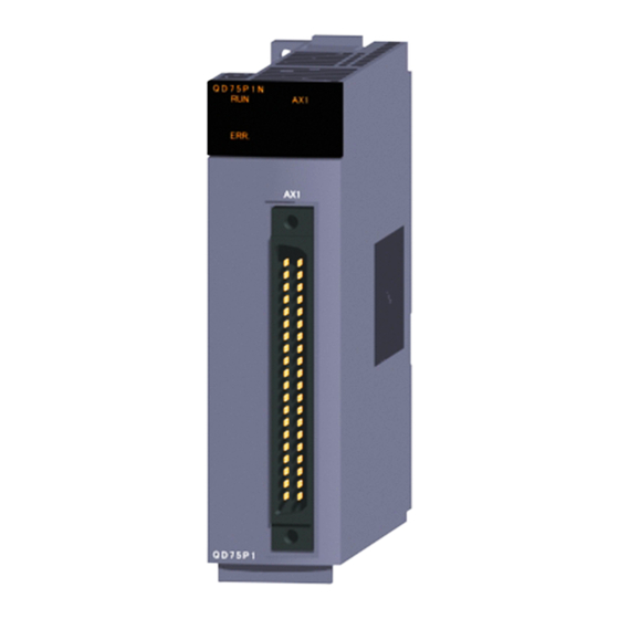
INSTALLATION, WIRING AND MAINTENANCE OF THE PRODUCT MELSEC-Q 4.1.2 Names of each part The part names of the QD75 are described with the QD75P N/QD75D N as an example. The QD75P N/QD75D N and QD75P /QD75D are different in the indication of their model names and serial numbers QD75P4N QD75D4N... - Page 92 OFF. standby. The symbols in the Display column indicate the following statuses: : Turns OFF. : Illuminates. : Flashes. The interface of each QD75 is as shown below. QD75P1N QD75P2N QD75P4N QD75D1N QD75D2N QD75D4N 4 - 4...
-
Page 93: Handling Precautions
INSTALLATION, WIRING AND MAINTENANCE OF THE PRODUCT MELSEC-Q 4.1.3 Handling precautions Handle the QD75 and cable while observing the following precautions. Handling precautions CAUTION Use the programmable controller in an environment that meets the general specifications contained in QCPU User's Manual(Hardware Design, Maintenance and Inspection) to use. Using this programmable controller in an environment outside the range of the general specifications may cause electric shock, fire, malfunction, and damage to or deterioration of the product. - Page 94 INSTALLATION, WIRING AND MAINTENANCE OF THE PRODUCT MELSEC-Q Other precautions Main body The main body case is made of plastic. Take care not to drop or apply strong impacts onto the case. Do not remove the QD75 PCB from the case. Failure to observe this could lead to faults.
-
Page 95: Installation
INSTALLATION, WIRING AND MAINTENANCE OF THE PRODUCT MELSEC-Q 4.2 Installation 4.2.1 Installation precautions The precautions for installing the QD75 are given below. Refer to this section as well as "4.1.3 Handling precautions" when carrying out the work. Installation precautions WARNING Completely turn off the externally supplied power used in the system before cleaning or tightening the screws. -
Page 96: Wiring
INSTALLATION, WIRING AND MAINTENANCE OF THE PRODUCT MELSEC-Q 4.3 Wiring The precautions for wiring the QD75 are given below. Refer to this section as well as "4.1.3 Handling precautions" when carrying out the work. 4.3.1 Wiring precautions Always confirm the terminal layout before connecting the wires to the QD75. (For the terminal layout, refer to Section 3.4.2 "Signal layout for external device connection connector".) Correctly solder the external wiring connector. - Page 97 INSTALLATION, WIRING AND MAINTENANCE OF THE PRODUCT MELSEC-Q [Applicable connectors] The table below shows applicable connectors for external devices. When wiring, use applicable wires and an appropriate tightening torque. Mitsubishi Electric 40-pin connector Wire Temperature Model Tightening torque Diameter Type...
- Page 98 INSTALLATION, WIRING AND MAINTENANCE OF THE PRODUCT MELSEC-Q [Processing example of shielded cables] Connect a cable with the FG wire and bind all shielded cables as shown below. 4 - 10...
- Page 99 INSTALLATION, WIRING AND MAINTENANCE OF THE PRODUCT MELSEC-Q Assembling of connector (A6CON1) Wrap the coated parts with a heat contractile tube. 4 - 11...
- Page 100 (except the one for pulse output) Use shielded twisted pair cables and an AD75CK type cable clamp (manufactured by Mitsubishi Electric) to ground the cables to the control box. Even when compliance with the EMC Directive is not required, attaching an AD75CK type cable clamp to the cable connected to the QD75 may reduce the influence of external noise.
- Page 101 INSTALLATION, WIRING AND MAINTENANCE OF THE PRODUCT MELSEC-Q [Wiring examples using duct (incorrect example and corrected example)] Wiring duct Relay Relay Drive Drive Relay unit unit Control panel The drive units are placed Programmable near the noise source. controller The connection cable Noise source between the QD75 and drive units is too long.
-
Page 102: Wiring Of The Differential Driver Common Terminal
INSTALLATION, WIRING AND MAINTENANCE OF THE PRODUCT MELSEC-Q 4.3.2 Wiring of the differential driver common terminal When the differential driver output system (QD75D N/QD75D ) is used, a potential difference between commons may occur between the differential driver common terminal and the differential receiver common terminal of the drive unit. To remove the potential difference between commons, connect the differential driver common terminal of the QD75D N/QD75D and the differential receiver common terminal of the drive... -
Page 103: Checking Installation And Wiring
INSTALLATION, WIRING AND MAINTENANCE OF THE PRODUCT MELSEC-Q 4.4 Checking installation and wiring 4.4.1 Items to check when installation and wiring are completed Check the following points when completed with the QD75 installation and wiring. Is the module correctly wired? ... "Connection confirmation" With "connection confirmation", the following three points are confirmed using GX Configurator-QP's connection confirmation function. -
Page 104: Maintenance
INSTALLATION, WIRING AND MAINTENANCE OF THE PRODUCT MELSEC-Q 4.5 Maintenance 4.5.1 Maintenance precautions The precautions for servicing the QD75 are given below. Refer to this section as well as "4.1.3 Handling precautions" when carrying out the work. WARNING Always turn all phases of the power supply OFF externally before cleaning or tightening the screws. -
Page 105: Data Used For Positioning Control
CHAPTER 5 DATA USED FOR POSITIONING CONTROL The parameters and data used to carry out positioning control with the QD75 are explained in this chapter. With the positioning system using the QD75, the various parameters and data explained in this chapter are used for control. The parameters and data include parameters set according to the device configuration, such as the system configuration, and parameters and data set according to each control. -
Page 106: Types Of Data
DATA USED FOR POSITIONING CONTROL MELSEC-Q 5.1 Types of data 5.1.1 Parameters and data required for control The parameters and data required to carry out control with the QD75 include the "setting data", "monitor data" and "control data" shown below. The data is set with the sequence program or peripheral device. - Page 107 DATA USED FOR POSITIONING CONTROL MELSEC-Q The only valid data assigned to basic parameters 2, detailed parameters 2, positioning data, or block start data are the data read at the moment when a positioning or JOG operation is started. Once the operation has started, any modification to the data is ignored.
- Page 108 DATA USED FOR POSITIONING CONTROL MELSEC-Q POINT (1) The "setting data" is created for each axis. (2) The "setting data" parameters have determined default values, and are set to the default values before shipment from the factory. (Parameters related to axes that are not used are left at the default value.) (3) The "setting data"...
-
Page 109: Setting Items For Positioning Parameters
DATA USED FOR POSITIONING CONTROL MELSEC-Q 5.1.2 Setting items for positioning parameters The table below lists items set to the positioning parameters. Setting of positioning parameters is similarly done for individual axes for all controls achieved by the QD75. For details of controls, refer to PART 2. For details of setting items, refer to Section 5.2 "List of parameters". - Page 110 DATA USED FOR POSITIONING CONTROL MELSEC-Q Control Major positioning control Manual control Position control Other control Positioning parameter Pr.25 Acceleration time 1 – – – Pr.26 Acceleration time 2 – – – Pr.27 Acceleration time 3 – – – 12.7.6 Pr.28 Deceleration time 1 –...
-
Page 111: Setting Items For Opr Parameters
DATA USED FOR POSITIONING CONTROL MELSEC-Q 5.1.3 Setting items for OPR parameters When carrying out "OPR control", the "OPR parameters" must be set. The setting items for the "OPR parameters" are shown below. The "OPR parameters" are set commonly for each axis. Refer to CHAPTER 8 "OPR CONTROL"... -
Page 112: Setting Items For Positioning Data
DATA USED FOR POSITIONING CONTROL MELSEC-Q 5.1.4 Setting items for positioning data Positioning data must be set for carrying out any "major positioning control". The table below lists the items to be set for producing the positioning data. One to 600 positioning data items can be set for each axis. For details of the major positioning controls, refer to CHAPTER 9 "MAJOR POSITIONING CONTROL". - Page 113 DATA USED FOR POSITIONING CONTROL MELSEC-Q : Always set, : Set as required, : Setting not possible –: Setting not required (This is an irrelevant item, so the set value will be ignored. If the value is the default value or within the setting range, there is no problem.) 1: Two control systems are available: the absolute (ABS) system and incremental (INC) system.
-
Page 114: Setting Items For Block Start Data
DATA USED FOR POSITIONING CONTROL MELSEC-Q 5.1.5 Setting items for block start data The "block start data" must be set when carrying out "high-level positioning control". The setting items for the " block start data" are shown below. Up to 50 points of " block start data" can be set for each axis. Refer to CHAPTER 10 "HIGH-LEVEL POSITIONING CONTROL"... -
Page 115: Setting Items For Condition Data
DATA USED FOR POSITIONING CONTROL MELSEC-Q 5.1.6 Setting items for condition data When carrying out "high-level positioning control" or using the JUMP instruction in the "major positioning control", the "condition data" must be set as required. The setting items for the "condition data" are shown below. Up to 10 "condition data"... -
Page 116: Types And Roles Of Monitor Data
DATA USED FOR POSITIONING CONTROL MELSEC-Q 5.1.7 Types and roles of monitor data The monitor data area in the buffer memory stores data relating to the operating state of the positioning system, which are monitored as required while the positioning system is operating. - Page 117 DATA USED FOR POSITIONING CONTROL MELSEC-Q Monitoring details Corresponding item Md.14 Axis in which the warning occurred Axis in which the warning occurred Axis warning No. Md.15 Axis warning No. Year:month Md.52 Axis warning occurrence (Year:month) (QD75P N/QD75D N Day:hour History of all warnings (QD75P N/QD75D N Axis warning...
- Page 118 DATA USED FOR POSITIONING CONTROL MELSEC-Q Monitoring the state Monitor details Corresponding item Md.26 Axis operation status Monitor the axis operation state Md.23 Axis error No. Monitor the latest error code that occurred with the axis Md.24 Axis warning No. Monitor the latest warning code that occurred with the axis Md.30 External input/output signal...
-
Page 119: Types And Roles Of Control Data
DATA USED FOR POSITIONING CONTROL MELSEC-Q 5.1.8 Types and roles of control data Operation of the positioning system is achieved through the execution of necessary controls. (Data required for controls are given through the default values when the power is switched ON, which can be modified as required by the sequence program.) Controls are performed over system data or machine operation. - Page 120 DATA USED FOR POSITIONING CONTROL MELSEC-Q Controlling the operation Controlling the operation Control details Corresponding item Cd.3 Set which positioning to execute (start No.) Positioning start No. Cd.5 Clear (reset) the axis error ( Md.23 ) and warning ( Md.24 ) Axis error reset Cd.6 Issue instruction to restart (When axis operation is stopped)
- Page 121 DATA USED FOR POSITIONING CONTROL MELSEC-Q Making settings related to operation Control details Corresponding item Cd.7 Turn M code ON signal OFF M code OFF request Cd.9 Set new value when changing current value New current value Cd.24 Speed-position switching enable flag Validate speed-position switching signal from external source Change movement amount for position control during speed-position Speed-position switching control...
-
Page 122: List Of Parameters
DATA USED FOR POSITIONING CONTROL MELSEC-Q 5.2 List of parameters 5.2.1 Basic parameters 1 Setting value buffer memory Setting value, setting range address Default Item value Value set with sequence Value set with peripheral device Axis 1 Axis 2 Axis 3 Axis 4 program 0 : mm 1 : inch... - Page 123 DATA USED FOR POSITIONING CONTROL MELSEC-Q Pr.2 to Pr.4 Movement amount per pulse These parameters define the amount of movement achieved by each single pulse within a pulse train output by the QD75. The following paragraphs explain how to set the individual parameters Pr.2 , Pr.3 , and Pr.4 assuming that the unit "mm"...
- Page 124 DATA USED FOR POSITIONING CONTROL MELSEC-Q However, the maximum value that can be set for this "movement amount per rotation (Al)" parameter is 6553.5 m (approx. 6.5mm). Set the "movement amount per rotation (Al)" as shown below so that the "movement amount per rotation (AL)" does not exceed this maximum value.
- Page 125 DATA USED FOR POSITIONING CONTROL MELSEC-Q Pr.5 Pulse output mode Set the pulse output mode to match the servo amplifier being used. IMPORTANT The only valid value of the " Pr.5 Pulse output mode" is the value at the moment when the PLC READY signal [Y0] turns from OFF to ON for the first time after the power is switched ON or the CPU module is reset.
- Page 126 DATA USED FOR POSITIONING CONTROL MELSEC-Q A phase/B phase mode Forward run and reverse run are controlled with the phase difference of the A phase (A ) and B phase (B ). When the B phase is 90 ° behind the A phase, the motor will forward run. ...
- Page 127 DATA USED FOR POSITIONING CONTROL MELSEC-Q Pr.6 Rotation direction setting Set the relation of the positioning direction ( Md.20 Current feed value increment direction/decrement direction) and the pulse output. For the relation of "Forward run pulse output, Reverse run pulse output" and "CW/A phase/PULSE signal, CCW/B phase/SIGN signal", refer to "...
-
Page 128: Basic Parameters 2
DATA USED FOR POSITIONING CONTROL MELSEC-Q Setting value buffer memory Setting value, setting range address Default Item value Value set with sequence Value set with peripheral device Axis 1 Axis 2 Axis 3 Axis 4 program The setting range differs depending on the " Pr.1 Unit setting". Here, the value within the [Table 1] range is set. - Page 129 DATA USED FOR POSITIONING CONTROL MELSEC-Q [Table 1] Pr.1 Value set with peripheral device (unit) Value set with sequence program (unit) setting value 0 to 2000000000 (×10 mm/min) 0 : mm 0 to 20000000.00 (mm/min) 0 to 2000000000 (×10 inch/min) 1 : inch 0 to 2000000.000 (inch/min) 2 : degree...
-
Page 130: Detailed Parameters 1
DATA USED FOR POSITIONING CONTROL MELSEC-Q 5.2.3 Detailed parameters 1 Setting value buffer memory Setting value, setting range address Item Default value Value set with Value set with peripheral device Axis 1 Axis 2 Axis 3 Axis 4 sequence program The setting value range differs according to the "... - Page 131 DATA USED FOR POSITIONING CONTROL MELSEC-Q 1) The backlash compensation is valid after machine OPR. Thus, if the backlash compensation amount is set or changed, always carry out machine OPR once. 2) The backlash compensation amount setting range is 0 to 65535, but it should be set to 255 or less by using the following expression.
- Page 132 DATA USED FOR POSITIONING CONTROL MELSEC-Q 1) Generally, the OP is set at the lower limit or upper limit of the stroke limit. 2) By setting the upper limit value or lower limit value of the software stroke limit, overrun can be prevented in the software. However, an emergency stop limit switch must be installed nearby outside the range.
- Page 133 DATA USED FOR POSITIONING CONTROL MELSEC-Q Pr.17 Torque limit setting value Set the maximum value of the torque generated by the servomotor as a percentage between 1 and 500%. The torque limit function limits the torque generated by the servomotor within the set range.
- Page 134 DATA USED FOR POSITIONING CONTROL MELSEC-Q Pr.18 M code ON signal output timing This parameter sets the M code ON signal output timing. Choose either WITH mode or AFTER mode as the M code ON signal output timing. WITH mode ..An M code is output and the M code ON AFTER mode ..
- Page 135 DATA USED FOR POSITIONING CONTROL MELSEC-Q Setting value buffer memory Setting value, setting range address Default Item value Value set with sequence Value set with peripheral device Axis 1 Axis 2 Axis 3 Axis 4 program 0 : Standard speed switching mode Pr.19 1 : Front-loading speed switching Speed switching mode...
- Page 136 DATA USED FOR POSITIONING CONTROL MELSEC-Q Pr.19 Speed switching mode Set whether to switch the speed switching mode with the standard switching or front-loading switching mode. 0 : Standard switching....Switch the speed when executing the next positioning data. 1 : Front-loading switching ..The speed switches at the end of the positioning data currently being executed.
- Page 137 DATA USED FOR POSITIONING CONTROL MELSEC-Q Pr.21 Current feed value during speed control Specify whether you wish to enable or disable the update of " Md.20 Current feed value" while operations are performed under the speed control (including the speed-position and position-speed switching control). 0: The update of the current feed value is disabled The current feed value will not change.
- Page 138 DATA USED FOR POSITIONING CONTROL MELSEC-Q Pr.70 Positioning option valid/invalid setting Enable or disable the data set in the positioning option (" Da.27 M code ON signal output timing", " Da.28 ABS direction in degrees", and " Da.29 Interpolation speed designation method") of the positioning data. Setting this parameter to "1: Valid"...
- Page 139 DATA USED FOR POSITIONING CONTROL MELSEC-Q MEMO 5 - 35...
-
Page 140: Detailed Parameters 2
DATA USED FOR POSITIONING CONTROL MELSEC-Q 5.2.4 Detailed parameters 2 Setting value buffer memory Setting value, setting range address Default Item value Value set with sequence Value set with peripheral device Axis 1 Axis 2 Axis 3 Axis 4 program Pr.25 Acceleration time 1 Pr.26 Acceleration time 2 Pr.27 Acceleration time 3... - Page 141 DATA USED FOR POSITIONING CONTROL MELSEC-Q [Table 1] Value set with peripheral device Value set with sequence program Pr.1 setting value (unit) (unit) 1 to 2000000000 ( 10 0 : mm 0.01 to 20000000.00 (mm/min) mm/min) 1 to 2000000000 ( 10 1 : inch 0.001 to 2000000.000 (inch/min) inch/min)
- Page 142 DATA USED FOR POSITIONING CONTROL MELSEC-Q Setting value buffer memory Setting value, setting range address Default Item value Value set with sequence Value set with peripheral device Axis 1 Axis 2 Axis 3 Axis 4 program 0 : Trapezoid Pr.34 acceleration/deceleration process Acceleration/deceleration 1 : S-curve...
- Page 143 DATA USED FOR POSITIONING CONTROL MELSEC-Q Pr.35 S-curve ratio Set the S-curve ratio (1 to 100%) for carrying out the S-curve acceleration/deceleration process. The S-curve ratio indicates where to draw the acceleration/deceleration curve using the sine curve as shown below. (Example) Positioning speed...
- Page 144 DATA USED FOR POSITIONING CONTROL MELSEC-Q Pr.36 Sudden stop deceleration time Set the time to reach speed 0 from " Pr.8 Speed limit value" (or " Pr.31 JOG speed limit value" during JOG operation) during the sudden stop. The illustration below shows the relationships with other parameters. 1) Positioning start 2) Sudden stop cause occurrence 3) Positioning stop...
- Page 145 DATA USED FOR POSITIONING CONTROL MELSEC-Q Pr.37 Stop group 1 sudden stop selection to Pr.39 Stop group 3 sudden stop selection Set the method to stop when the stop causes in the following stop groups occur. Stop group 1 ..... Stop with hardware stroke limit ...
- Page 146 DATA USED FOR POSITIONING CONTROL MELSEC-Q Setting value buffer memory Setting value, setting range address Default Item value Value set with sequence Value set with peripheral device Axis 1 Axis 2 Axis 3 Axis 4 program 0 to 65535 (ms) 0 to 32767 : Pr.40 Set as a decimal...
- Page 147 DATA USED FOR POSITIONING CONTROL MELSEC-Q [Table 1] Value set with peripheral device Value set with sequence program Pr.1 setting value (unit) (unit) 0 to 100000 ( 10 m) 0 to 10000.0 ( m) 0 : mm 0 to 100000 ( ...
- Page 148 DATA USED FOR POSITIONING CONTROL MELSEC-Q Pr.42 External command function selection Select a command with which the external command signal should be associated. 0: External positioning start The external command signal input is used to start a positioning operation. 1: External speed change request The external command signal input is used to change the speed in the current positioning operation.
-
Page 149: Opr Basic Parameters
DATA USED FOR POSITIONING CONTROL MELSEC-Q 5.2.5 OPR basic parameters Setting value buffer memory Setting value, setting range address Default Item value Value set with sequence Value set with peripheral device Axis 1 Axis 2 Axis 3 Axis 4 program 0 : Near-point dog method 1 : Stopper method 1) Pr.43... - Page 150 DATA USED FOR POSITIONING CONTROL MELSEC-Q 1 : Stopper method 1) (1) Start machine OPR. (Start movement at the " Pr.46 OPR speed" in the OPR speed Pr.46 " Pr.44 OPR direction".) (2) Detect the near-point dog ON, and start deceleration. Creep speed Pr.47 (3) Decelerate to "...
- Page 151 DATA USED FOR POSITIONING CONTROL MELSEC-Q 4 : Count method 1) (1) Start machine OPR. (Start movement at the " Pr.46 OPR speed" in the " Pr.44 OPR direction".) (2) Detect the near-point dog ON, and start deceleration. (3) Decelerate to " Pr.47 Creep speed", and move with the creep speed.
- Page 152 DATA USED FOR POSITIONING CONTROL MELSEC-Q Pr.44 OPR direction Set the direction to start movement when starting machine OPR. 0: Positive direction (address increment direction) Moves in the direction that the address increments. (Arrow 2)) 1: Negative direction (address decrement direction) Moves in the direction that the address decrements.
- Page 153 DATA USED FOR POSITIONING CONTROL MELSEC-Q Pr.45 OP address Set the address used as the reference point for positioning control (ABS system). (When the machine OPR is completed, the stop position address is changed to the address set in " Pr.45 OP address". At the same time, the " Pr.45 OP address"...
- Page 154 DATA USED FOR POSITIONING CONTROL MELSEC-Q Pr.47 Creep speed Set the creep speed after near-point dog ON (the low speed just before stopping after decelerating from the OPR speed). The creep speed is set within the following range. ( Pr.46 OPR speed ) ( Pr.47 Creep speed) ( Pr.7 Bias speed at start) Note) The creep speed is related to the detection error when using the OPR...
- Page 155 DATA USED FOR POSITIONING CONTROL MELSEC-Q Pr.48 OPR retry Set whether to carry out OPR retry. When the OPR retry function is validated and the machine OPR is started, first the axis will move in the OPR direction (1)). If the upper/lower limit signal turns OFF before the near-point dog signal ON is detected (2)), the axis will decelerate to a stop, and then will move in the direction opposite to the specified OPR direction (3)).
-
Page 156: Opr Detailed Parameters
DATA USED FOR POSITIONING CONTROL MELSEC-Q 5.2.6 OPR detailed parameters Setting value buffer memory Setting value, setting range Default address Item value Value set with sequence Value set with peripheral device Axis 1 Axis 2 Axis 3 Axis 4 program 0 to 65535 (ms) 0 to 32767 : Pr.49... - Page 157 DATA USED FOR POSITIONING CONTROL MELSEC-Q [Table 1] Value set with peripheral device Value set with sequence program Pr.1 setting value (unit) (unit) 0 to 2147483647 ( 10 m) 0 to 214748364.7 ( m) 0 : mm 0 to 2147483647 ( ...
- Page 158 DATA USED FOR POSITIONING CONTROL MELSEC-Q Setting value buffer memory Setting value, setting range address Default Item value Value set with peripheral Value set with sequence program Axis 1 Axis 2 Axis 3 Axis 4 device The setting value range differs depending on the " Pr.1 Unit setting". Here, the value within the [Table 1] range is set.
- Page 159 DATA USED FOR POSITIONING CONTROL MELSEC-Q [Table 1] Value set with peripheral device Value set with sequence program Pr.1 setting value (unit) (unit) -2147483648 to 2147483647 ( 10 m) -214748364.8 to 214748364.7 ( m) 0 : mm -2147483648 to 2147483647 ( ...
-
Page 160: List Of Positioning Data
DATA USED FOR POSITIONING CONTROL MELSEC-Q 5.3 List of positioning data Before explaining the positioning data setting items Da.1 to Da.10 , the configuration of the positioning data will be shown below. Before the explanation on the positioning data setting items Da.1 to Da.10 and Da.27 to Da.29 , the configuration of the positioning data will be shown below. - Page 161 DATA USED FOR POSITIONING CONTROL MELSEC-Q The descriptions that follow relate to the positioning data set items ( Da.1 to Da.10 , Da.27 to Da.29 ). (The buffer memory addresses shown are those of the "positioning data No. 1" for the axes 1 to 4.) 5 - 57...
- Page 162 DATA USED FOR POSITIONING CONTROL MELSEC-Q Positioning identifier configuration The positioning identifier consists of " Da.1 Operation pattern" to " Da.5 Axis to be interpolated". The set values of those data are stored in one buffer memory address. Consider the positioning identifier configuration in the figure below when setting "...
- Page 163 DATA USED FOR POSITIONING CONTROL MELSEC-Q The following table lists the setting range and default value of each buffer memory area of the positioning identifier. Setting value Setting value buffer memory address Value set with Default Item value Value set with peripheral device sequence Axis 1 Axis 2...
- Page 164 DATA USED FOR POSITIONING CONTROL MELSEC-Q Da.1 Operation pattern The operation pattern designates whether positioning of a certain data No. is to be ended with just that data, or whether the positioning for the next data No. is to be carried out in succession.
- Page 165 DATA USED FOR POSITIONING CONTROL MELSEC-Q Da.5 Axis to be interpolated Set the target axis (partner axis) for operations under the 2-axis interpolation control, and the circular interpolation axis for operations under the 3-axis helical interpolation control. 0 : Selects the axis 1 as the target axis (partner axis). 1 : Selects the axis 2 as the target axis (partner axis).
- Page 166 DATA USED FOR POSITIONING CONTROL MELSEC-Q Setting value buffer memory Setting value, setting range Default address Item Value set with sequence value Value set with peripheral device Axis 1 Axis 2 Axis 3 Axis 4 program The setting value range differs according to the " Da.2 Control system".
- Page 167 DATA USED FOR POSITIONING CONTROL MELSEC-Q [Table 1] When " Pr.1 Unit Setting" is "mm" The table below lists the control systems that require the setting of the positioning address or movement amount and the associated setting ranges. (With any control system excluded from the table below, neither the positioning address nor the movement amount needs to be set.) Value set with peripheral device Value set with sequence program...
- Page 168 DATA USED FOR POSITIONING CONTROL MELSEC-Q Speed-position switching control INC mode: Set the amount of movement after the switching from speed control to position control. ABS mode: Set the absolute address which will be the target value after speed control is switched to position control.
- Page 169 DATA USED FOR POSITIONING CONTROL MELSEC-Q When " Pr.1 Unit Setting" is "pulse" The table below lists the control systems that require the setting of the positioning address or movement amount and the associated setting ranges. (With any control system excluded from the table below, neither the positioning address nor the movement amount needs to be set.) Value set with peripheral device Value set with sequence program...
- Page 170 DATA USED FOR POSITIONING CONTROL MELSEC-Q When " Pr.1 Unit Setting" is "inch" The table below lists the control systems that require the setting of the positioning address or movement amount and the associated setting ranges. (With any control system excluded from the table below, neither the positioning address nor the movement amount needs to be set.) Value set with sequence program Value set with peripheral device...
- Page 171 DATA USED FOR POSITIONING CONTROL MELSEC-Q Setting value buffer memory Setting value, setting range address Default Item value Value set with sequence Value set with peripheral device Axis 1 Axis 2 Axis 3 Axis 4 program The setting value range differs according to the " Da.2 Control system".
- Page 172 DATA USED FOR POSITIONING CONTROL MELSEC-Q [Table 1] When " Pr.1 Unit Setting" is "mm" The table below lists the control systems that require the setting of the arc address and shows the setting range. (With any control system excluded from the table below, the arc address does not need to be set.) Value set with sequence program Value set with peripheral device...
- Page 173 DATA USED FOR POSITIONING CONTROL MELSEC-Q When " Pr.1 Unit Setting" is "inch" The table below lists the control systems that require the setting of the arc address and shows the setting range. (With any control system excluded from the table below, the arc address does not need to be set.) Value set with sequence program Value set with peripheral device...
- Page 174 DATA USED FOR POSITIONING CONTROL MELSEC-Q Setting value buffer memory Setting value, setting range address Default Item value Value set with sequence Value set with peripheral device Axis 1 Axis 2 Axis 3 Axis 4 program The setting value range differs depending on the " Pr.1 Unit setting".
- Page 175 DATA USED FOR POSITIONING CONTROL MELSEC-Q Da.10 M code (or condition data No./No. of LOOP to LEND repetitions) Set an "M code", a "condition data No. ", or the "number of LOOP to LEND repetitions" depending on how the " Da.2 Control system" is set. ...
- Page 176 DATA USED FOR POSITIONING CONTROL MELSEC-Q Da.9 Dwell time (JUMP designation positioning data No.) Set the "dwell time" or "positioning data No." corresponding to the " Da.2 Control system". When a method other than "JUMP instruction " is set for " Da.2 Control system"...
- Page 177 DATA USED FOR POSITIONING CONTROL MELSEC-Q Setting value, setting range Setting value buffer memory address Default Item Value set with sequence value Value set with peripheral Axis 1 Axis 2 Axis 3 Axis 4 program 0: Use the set value in " Pr.18 M Da.27 code ON signal output timing".
-
Page 178: List Of Block Start Data
DATA USED FOR POSITIONING CONTROL MELSEC-Q 5.4 List of block start data The illustrations below show the organization of the block start data stored in the QD75 buffer memory. The block start data setting items Da.11 to Da.14 are explained in the pages that follow. - Page 179 DATA USED FOR POSITIONING CONTROL MELSEC-Q 50th point Buffer memory Setting item address 2nd point Buffer memory 1st point Setting item address 28049 Buffer memory Setting item address œ ˆ Ê ’ u Œ ˆ ‚ ß Ž n “ ® ƒ f [ ƒ ^ 28001 28000 Da.12 Start data No.
- Page 180 DATA USED FOR POSITIONING CONTROL MELSEC-Q REMARK To perform an high-level positioning control using block start data, set a number between 7000 and 7004 to the " Cd.3 Positioning start No." and use the " Cd.4 Positioning starting point No." to specify a point number between 1 and 50, a position counted from the beginning of the block.
- Page 181 DATA USED FOR POSITIONING CONTROL MELSEC-Q Setting value buffer memory Setting value address Default Item value Value set with peripheral Value set with sequence program Axis 1 Axis 2 Axis 3 Axis 4 device 0 : End Da.11 Shape 0 0 0 1 : Continue 0000 26000 27000 28000 29000...
- Page 182 DATA USED FOR POSITIONING CONTROL MELSEC-Q Da.11 Shape Set whether to carry out only the local "block start data" and then end control, or to execute the "block start data" set in the next point. Setting value Setting details 0 : End Execute the designated point's "block start data", and then complete the control.
- Page 183 DATA USED FOR POSITIONING CONTROL MELSEC-Q Da.14 Parameter Set the value as required for " Da.13 Special start instruction ". Da.13 Special start instruction Setting value Setting details Block start (Normal start) – Not used. (There is no need to set.) Set the condition data No.
-
Page 184: List Of Condition Data
DATA USED FOR POSITIONING CONTROL MELSEC-Q 5.5 List of condition data The illustrations below show the organization of the condition data stored in the QD75 buffer memory. The condition data setting items Da.15 to Da.19 are explained in the pages that follow. No.10 Buffer memory Setting item... - Page 185 DATA USED FOR POSITIONING CONTROL MELSEC-Q No.10 Buffer memory Setting item address No.2 Buffer memory No.1 Setting item address 28190 Buffer memory Setting item address 28110 28191 28192 28100 28193 Da.16 Condition Da.15 Condition 28194 28111 operator target 28195 28112 Open 28101 28196...
- Page 186 DATA USED FOR POSITIONING CONTROL MELSEC-Q REMARK To perform an high-level positioning control using block start data, set a number between 7000 and 7004 to the " Cd.3 Positioning start No." and use the " Cd.4 Positioning starting point No." to specify a point number between 1 and 50, a position counted from the beginning of the block.
- Page 187 DATA USED FOR POSITIONING CONTROL MELSEC-Q Setting value buffer memory Setting value Default address Item value Value set with peripheral device Value set with sequence program Axis 1 Axis 2 Axis 3 Axis 4 01 : Device X 02 : Device Y Da.15 Condition target 03 : Buffer memory (1-word)
- Page 188 DATA USED FOR POSITIONING CONTROL MELSEC-Q Da.15 Condition target Set the condition target as required for each control. Setting value Setting details : Device X Set the input/output signal ON/OFF of the QD75 as the conditions. : Device Y : Buffer memory (1-word) Set the value stored in the buffer memory as the condition. : The target buffer memory is "1-word (16 bits)"...
- Page 189 DATA USED FOR POSITIONING CONTROL MELSEC-Q Da.18 Parameter 1 Set the parameters as required for the " Da.16 Condition operator". Da.16 Condition operator Setting value Setting details : =P1 : P1 The value of P1 should be equal to or smaller than the value of : ...
-
Page 190: List Of Monitor Data
DATA USED FOR POSITIONING CONTROL MELSEC-Q 5.6 List of monitor data 5.6.1 System monitor data Storage item Storage details Whether the mode is the test mode from the peripheral device or not is stored. Md.1 In test mode flag When not in test mode : OFF ... - Page 191 DATA USED FOR POSITIONING CONTROL MELSEC-Q Storage buffer memory address Reading the monitor value Default value (common for axis 1 to axis 4) Monitoring is carried out with a decimal. Monitor Storage value 1200 value 0: Not in test mode 1: In test mode (Unless noted in particular, the monitor value is saved as binary data.) 5 - 87...
- Page 192 DATA USED FOR POSITIONING CONTROL MELSEC-Q Storage item Storage details Reading the monitor value [Storage details] This area stores the start information (restart flag, start origin, and start axis): Restart flag: Indicates whether the operation has or has not been halted and restarted.
- Page 193 DATA USED FOR POSITIONING CONTROL MELSEC-Q Default value Storage buffer memory address (common to axes 1 to 4) 0000 0000 0000 0000 0000 5 - 89...
- Page 194 DATA USED FOR POSITIONING CONTROL MELSEC-Q Storage item Storage details Reading the monitor value [Storage details] This area stores the following results of the error judgment performed upon starting: BUSY start warning flag Error flag Error No. [Reading the monitor value] Monitoring is carried out with a hexadecimal display.
- Page 195 DATA USED FOR POSITIONING CONTROL MELSEC-Q Default value Storage buffer memory address (common to axes 1 to 4) 0000 1292 5 - 91...
- Page 196 DATA USED FOR POSITIONING CONTROL MELSEC-Q Storage item Storage details Reading the monitor value Monitoring is carried out with a decimal display. Md.9 Stores a number (Axis No.) Monitor Storage value Axis in which that indicates the axis that value 1: Axis 1 the error 2: Axis 2...
- Page 197 DATA USED FOR POSITIONING CONTROL MELSEC-Q Default value Storage buffer memory address (common to axes 1 to 4) 0000 0000 0000 1357 5 - 93...
- Page 198 DATA USED FOR POSITIONING CONTROL MELSEC-Q Storage item Storage details Reading the monitor value Monitoring is carried out with a decimal display. Md.14 Stores a number (Axis No.) Monitor Storage value Axis in which that indicates the axis that value 1: Axis 1 the warning 2: Axis 2...
- Page 199 DATA USED FOR POSITIONING CONTROL MELSEC-Q Default value Storage buffer memory address (common to axes 1 to 4) 0000 0000 0000 1422 1424 1425 5 - 95...
-
Page 200: Axis Monitor Data
DATA USED FOR POSITIONING CONTROL MELSEC-Q 5.6.2 Axis monitor data Storage item Storage details The currently commanded address is stored. (Different from the actual motor position during operation) The current position address is stored. If "degree" is selected as the unit, the addresses will have a ring structure for values between 0 and 359.99999 degrees. - Page 201 DATA USED FOR POSITIONING CONTROL MELSEC-Q Storage buffer Default memory address Reading the monitor value value Axis 1 Axis 2 Axis 3 Axis 4 Monitoring is carried out with a hexadecimal. Low-order buffer memory Example) 800 Monitor value 1100 1000 0000 1001 1101...
- Page 202 DATA USED FOR POSITIONING CONTROL MELSEC-Q Storage item Storage details Whenever an axis warning is reported, a related warning code is stored. This area stores the latest warning code always. (Whenever an axis warning is Md.24 Axis warning No. reported, a new warning code replaces the stored warning code.) ...
- Page 203 DATA USED FOR POSITIONING CONTROL MELSEC-Q Storage buffer Default memory address Reading the monitor value value Axis 1 Axis 2 Axis 3 Axis 4 Monitoring is carried out with a decimal display. Monitor Warning No. 1007 1107 value For details of warning Nos. (warning codes), refer to Section 15.4 "List of warnings".
- Page 204 DATA USED FOR POSITIONING CONTROL MELSEC-Q Storage item Storage details The speed which is actually output as a command at that time in each axis is stored. (May be different from the actual motor speed) Md.28 Axis feedrate "0" is stored when the axis is at a stop. Update timing: 0.9ms (QD75P N/QD75D N), 56.8ms (QD75P /QD75D ) ...
- Page 205 DATA USED FOR POSITIONING CONTROL MELSEC-Q Storage buffer Default memory address Reading the monitor value value Axis 1 Axis 2 Axis 3 Axis 4 Monitoring is carried out with a hexadecimal. Low-order buffer memory Example) 812 Monitor value High-order buffer memory Example) 813 1012 1112 0000...
- Page 206 DATA USED FOR POSITIONING CONTROL MELSEC-Q Storage item Storage details This area stores the states (ON/OFF) of various flags. Information on the following flags is stored. In speed control flag: This signal that comes ON under the speed control can be used to judge whether the operation is performed under the speed control or position control.
- Page 207 DATA USED FOR POSITIONING CONTROL MELSEC-Q Storage buffer Default memory address Reading the monitor value value Axis 1 Axis 2 Axis 3 Axis 4 Monitoring is carried out with a hexadecimal display. Monitor value Buffer 0 0 0 0 0 0 0 0 0 0 0 0 1 0 0 0 memory 0008 1017 1117...
- Page 208 DATA USED FOR POSITIONING CONTROL MELSEC-Q Storage item Storage details During operation with positioning data : The actual target speed, considering the override and speed limit value, etc., is stored. "0" is stored when positioning is completed. During interpolation of position control : The composite speed or reference axis speed is stored in the reference axis address, and "0"...
- Page 209 DATA USED FOR POSITIONING CONTROL MELSEC-Q Storage buffer Default memory address Reading the monitor value value Axis 1 Axis 2 Axis 3 Axis 4 Monitoring is carried out with a hexadecimal display. Low-order buffer memory Example) 820 Monitor value High-order buffer memory Example) 821 1020 1120 0000...
- Page 210 DATA USED FOR POSITIONING CONTROL MELSEC-Q Storage item Storage details Md.36 Special start data instruction The " instruction code" used with special start and indicated by the start data code setting value pointer currently being executed is stored. The " instruction parameter" used with special start and indicated by the start data Md.37 Special start data instruction pointer currently being executed is stored.
- Page 211 DATA USED FOR POSITIONING CONTROL MELSEC-Q Storage buffer Default memory address Reading the monitor value value Axis 1 Axis 2 Axis 3 Axis 4 Monitoring is carried out with a decimal display. Monitor Storage value value 00: Block start (Normal start) 01: Condition start 1027 1127 02: Wait start...
- Page 212 DATA USED FOR POSITIONING CONTROL MELSEC-Q Storage item Storage details This area stores the remaining number of repetitions during "repetitions" specific to special starting. Md.41 Special start repetition The count is decremented by one (-1) at the loop end. counter ...
- Page 213 DATA USED FOR POSITIONING CONTROL MELSEC-Q Storage buffer Default memory address Reading the monitor value value Axis 1 Axis 2 Axis 3 Axis 4 Monitoring is carried out with a decimal display. Storage value 1032 1132 0 to 255 Monitor value Monitoring is carried out with a hexadecimal display.
-
Page 214: List Of Control Data
DATA USED FOR POSITIONING CONTROL MELSEC-Q 5.7 List of control data 5.7.1 System control data Setting item Setting details Requests writing of data (parameters, positioning data, and block start data) from Cd.1 Flash ROM write request the buffer memory to the flash ROM. ... - Page 215 DATA USED FOR POSITIONING CONTROL MELSEC-Q Storage buffer memory address Setting value Default value (common to axes 1 to 4) Set with a decimal. Setting value 1900 Flash ROM write request 1: Requests write access to flash ROM. The QD75 resets the value to "0" automatically when the write access completes. (This indicates the completion of write operation.) Set with a decimal.
- Page 216 DATA USED FOR POSITIONING CONTROL MELSEC-Q Setting item Setting details Select the timing to output the difference ( ) between the actual and the set Cd.43 Output timing selection of positioning end addresses in continuous path control, in which the difference near pass control ) is output during the execution of the next positioning data.
- Page 217 DATA USED FOR POSITIONING CONTROL MELSEC-Q Storage buffer memory address Setting value Default value (common to axes 1 to 4) Set with a decimal. Setting value 1934 Output timing selection of near pass control 0: At constant speed 1: At deceleration 5 - 113...
-
Page 218: Axis Control Data
DATA USED FOR POSITIONING CONTROL MELSEC-Q 5.7.2 Axis control data Setting item Setting details Set the positioning start No. Cd.3 Positioning start No. (Only 1 to 600 for the Pre-reading start function. For details, refer to Section 12.7.7 "Pre-reading start function".) ... - Page 219 DATA USED FOR POSITIONING CONTROL MELSEC-Q Storage buffer Default memory address Setting value value Axis 1 Axis 2 Axis 3 Axis 4 Set with a decimal. Setting value 1500 1600 1700 1800 Positioning data No. : Positioning data No. 1 to 600 : Block start designation 7000 to7004 : Machine OPR...
- Page 220 DATA USED FOR POSITIONING CONTROL MELSEC-Q Setting item Setting details Cd.8 External command valid Validates or in validates external command signals. When changing the "current feed value" using the start No. "9003", use this data item to specify a new feed value. ...
- Page 221 DATA USED FOR POSITIONING CONTROL MELSEC-Q Storage buffer Default memory address Setting value value Axis 1 Axis 2 Axis 3 Axis 4 Set with a decimal. Setting value 1505 1605 1705 1805 External command valid 0: Invalidates an external command. 1: Validates an external command.
- Page 222 DATA USED FOR POSITIONING CONTROL MELSEC-Q Setting item Setting details When changing the acceleration time during a speed change, use this data item to specify a new acceleration time. Cd.10 New acceleration time value Cd.10 setting range (unit) 0 to 8388608 (ms) ...
- Page 223 DATA USED FOR POSITIONING CONTROL MELSEC-Q Storage buffer Default memory address Setting value value Axis 1 Axis 2 Axis 3 Axis 4 1508 1608 1708 1808 Set with a decimal. 1509 1609 1709 1809 Cd.10 New acceleration time value Setting value Cd.11 New deceleration time value Example: When the "...
- Page 224 DATA USED FOR POSITIONING CONTROL MELSEC-Q Setting item Setting details To use the positioning operation speed override function, use this data item to specify an "override" value. For details of the override function, refer to Section 12.5.2" Override function". Cd.13 Positioning operation speed override If the speed becomes lower than the minimum unit due to override 1% or...
- Page 225 DATA USED FOR POSITIONING CONTROL MELSEC-Q Storage buffer Default memory address Setting value value Axis 1 Axis 2 Axis 3 Axis 4 Set with a decimal. Setting value 1513 1613 1713 1813 Override value (%) 1 to 300 Set with a decimal. Actual value Cd.14 New speed value Conversion into an integer value...
- Page 226 DATA USED FOR POSITIONING CONTROL MELSEC-Q Setting item Setting details Use this data item to set the amount of movement by inching. The machine performs a JOG operation if "0" is set. Set a value within the following range: inch degree pulse...
- Page 227 DATA USED FOR POSITIONING CONTROL MELSEC-Q Storage buffer Default memory address Setting value value Axis 1 Axis 2 Axis 3 Axis 4 Set with a decimal. Actual value Cd.16 Inching movement amount Conversion into an integer value Unit conversion table ( Cd.16 ) Unit Setting value 1517 1617 1717 1817...
- Page 228 DATA USED FOR POSITIONING CONTROL MELSEC-Q Setting item Setting details Cd.19 OPR request flag OFF The sequence program can use this data item to forcibly turn the OPR request flag from ON to OFF. request This data item determines the factor by which the number of pulses from the manual pulse generator is magnified.
- Page 229 DATA USED FOR POSITIONING CONTROL MELSEC-Q Storage buffer Default memory address Setting value value Axis 1 Axis 2 Axis 3 Axis 4 Set with a decimal. Setting value OPR request flag OFF request 1521 1621 1721 1821 1: Turns the "OPR request flag" from ON to OFF.
- Page 230 DATA USED FOR POSITIONING CONTROL MELSEC-Q Setting item Setting details During the speed control stage of the speed-position switching control (INC mode), it is possible to change the specification of the movement amount during the position control stage. For that, use this data item to specify a new movement amount.
- Page 231 DATA USED FOR POSITIONING CONTROL MELSEC-Q Storage buffer Default memory address Setting value value Axis 1 Axis 2 Axis 3 Axis 4 Set with a decimal. Speed-position switching Cd.23 Actual value control movement amount change register Conversion into an integer value Unit conversion table ( Cd.23 ) Unit 1526...
- Page 232 DATA USED FOR POSITIONING CONTROL MELSEC-Q Setting item Setting details Cd.26 Position-speed switching Set whether the external control signal (external command signal [CHG]: "speed- enable flag position, position-speed switching request" is selected) is enabled or not. When changing the target position during a positioning operation, use this data item to specify a new positioning address.
- Page 233 DATA USED FOR POSITIONING CONTROL MELSEC-Q Storage buffer Default memory address Setting value value Axis 1 Axis 2 Axis 3 Axis 4 Set with a decimal. Setting value 1532 1632 1732 1832 Position-speed switching enable flag 0: Position control will not be taken over by speed control even when the external command signal [CHG] comes ON.
- Page 234 DATA USED FOR POSITIONING CONTROL MELSEC-Q Setting item Setting details Cd.30 Simultaneous starting axis start data No. (axis 1 start data No.) Cd.31 Simultaneous starting axis start data No. (axis 2 start data No.) Use these data items to specify a start data No. for each axis that has to start simultaneously.
- Page 235 DATA USED FOR POSITIONING CONTROL MELSEC-Q Storage buffer Default memory address Setting value value Axis 1 Axis 2 Axis 3 Axis 4 1540 1640 1740 1840 Set with a decimal. 1541 1641 1741 1841 Setting value Cd.30 to Cd.33 Simultaneous starting 1542 1642 1742 1842 axis start data No.: 1 to 600...
- Page 236 DATA USED FOR POSITIONING CONTROL MELSEC-Q Setting item Setting details To continue the step operation when the step function is used, set "1" in this data Cd.36 Step start information item. To skip the current positioning operation, set "1" in this data item. Cd.37 Skip command ...
- Page 237 DATA USED FOR POSITIONING CONTROL MELSEC-Q Storage buffer Default memory address Setting value value Axis 1 Axis 2 Axis 3 Axis 4 Set with a decimal. 1546 1646 1746 1846 Set with a decimal. Setting value Skip request 1547 1647 1747 1847 Issues a skip request to have the machine decelerate, stop, and then start the next positioning...
- Page 238 DATA USED FOR POSITIONING CONTROL MELSEC-Q MEMO 5 - 134...
-
Page 239: Sequence Program Used For Positioning Control
CHAPTER 6 SEQUENCE PROGRAM USED FOR POSITIONING CONTROL The programs required to carry out positioning control with the QD75 are explained in this chapter. The program required for control is created allowing for the "start conditions", "start time chart", "device settings" and general control configuration. (The parameters, positioning data, block start data and condition data, etc., must be set in the QD75 according to the control to be executed, and program for setting the control data or a program for starting the various control must be created.) -
Page 240: Precautions For Creating Program
SEQUENCE PROGRAM USED FOR POSITIONING CONTROL MELSEC-Q 6.1 Precautions for creating program The common precautions to be taken when writing data from the CPU module to the QD75 buffer memory are described below. When diverting any of the program examples introduced in this manual to the actual system, fully verify that there are no problems in the controllability of the target system. - Page 241 SEQUENCE PROGRAM USED FOR POSITIONING CONTROL MELSEC-Q System configuration Unless particularly designated, the sequence program for the following system is shown in this chapter and subsequent. In the program, the unit of "0 (mm)" is set for the basic parameter 1. Refer to Section 6.2 for the application of the devices to be used.
- Page 242 SEQUENCE PROGRAM USED FOR POSITIONING CONTROL MELSEC-Q (b) When the circuit uses the "intelligent function device" on the source(s) side and the destination (D) side of a MOV instruction, change the instruction to a FROM instruction and a TO instruction. MOVP G826 Set the...
-
Page 243: List Of Devices Used
SEQUENCE PROGRAM USED FOR POSITIONING CONTROL MELSEC-Q 6.2 List of devices used In the sequence programs shown in this chapter and subsequent, the application of the devices used are as follows. The I/O numbers for QD75 indicate those when QD75 is mounted in the 0-slot of the main base. - Page 244 SEQUENCE PROGRAM USED FOR POSITIONING CONTROL MELSEC-Q Device Device Application Details when ON name Axis 1 Axis 2 Axis 3 Axis 4 M code OFF command Commanding M code OFF JOG operation speed setting Commanding JOG operation speed command setting Commanding forward run JOG/inching Forward run JOG/inching command operation...
- Page 245 SEQUENCE PROGRAM USED FOR POSITIONING CONTROL MELSEC-Q Device Device Application Details when ON name Axis 1 Axis 2 Axis 3 Axis 4 OPR request OFF command Commanding OPR request OFF OPR request OFF command pulse OPR request OFF commanded OPR request OFF command storage OPR request OFF command held Fast OPR command Commanding fast OPR Fast OPR command storage...
- Page 246 SEQUENCE PROGRAM USED FOR POSITIONING CONTROL MELSEC-Q Device Device Application Details when ON name Axis 1 Axis 2 Axis 3 Axis 4 ZP.TEACH1 instruction complete device ZP.TEACH1 instruction completed ZP.TEACH1 instruction failure device ZP.TEACH1 instruction failed ZP.PINIT instruction complete device ZP.PINIT instruction completed ZP.PINIT instruction failure device ZP.PINIT instruction failed...
- Page 247 SEQUENCE PROGRAM USED FOR POSITIONING CONTROL MELSEC-Q Device Device Application Details of storage name Axis 1 Axis 2 Axis 3 Axis 4 Acceleration time setting (low-order 16 bits) ( Cd.10 New acceleration time value) Acceleration time setting (high-order 16 bits) Deceleration time setting (low-order 16 bits) ( Cd.11 New deceleration time...
- Page 248 SEQUENCE PROGRAM USED FOR POSITIONING CONTROL MELSEC-Q Device Device Application Details of storage name Axis 1 Axis 2 Axis 3 Axis 4 ( Pr.3 Movement amount per Movement amount per rotation rotation) Unit magnification ( Pr.4 Unit magnification) Pulse output mode ( Pr.5 Pulse output mode) Rotation direction setting ( Pr.6 Rotation direction setting)
-
Page 249: Creating A Program
6 SEQUENCE PROGRAM USED FOR POSITIONING CONTROL MELSEC-Q 6.3 Creating a program The "positioning control operation program" actually used is explained in this chapter. The functions and programs explained in PART 2 are assembled into the "positioning control operation program" explained here. (To monitor the control, add the required monitor program that matches the system. -
Page 250: Positioning Control Operation Program
6 SEQUENCE PROGRAM USED FOR POSITIONING CONTROL MELSEC-Q 6.3.2 Positioning control operation program The various programs that configure the "positioning control operation program" are shown below. When creating the program, refer to the explanation of each program and Section 6.4 "Positioning program examples", and create an operation program that matches the positioning system. - Page 251 6 SEQUENCE PROGRAM USED FOR POSITIONING CONTROL MELSEC-Q 6 - 13...
- Page 252 6 SEQUENCE PROGRAM USED FOR POSITIONING CONTROL MELSEC-Q Continued from previous page Sub program Program added according to No.14 control details. Speed change program Refer to Section 12.5.1 (Create as required.) No.15 Override program Refer to Section 12.5.2 No.16 Acceleration/deceleration time Refer to Section 12.5.3 change program No.17...
-
Page 253: Positioning Program Examples
SEQUENCE PROGRAM USED FOR POSITIONING CONTROL MELSEC-Q 6.4 Positioning program examples An example of the "Axis 1" positioning program is given in this section. [No. 1] to [No. 3] parameter and data setting program When setting the parameters or data with the sequence program, set them in the QD75 using the TO instruction from the CPU module. - Page 254 SEQUENCE PROGRAM USED FOR POSITIONING CONTROL MELSEC-Q 6 - 16...
- Page 255 SEQUENCE PROGRAM USED FOR POSITIONING CONTROL MELSEC-Q 6 - 17...
- Page 256 SEQUENCE PROGRAM USED FOR POSITIONING CONTROL MELSEC-Q 6 - 18...
- Page 257 SEQUENCE PROGRAM USED FOR POSITIONING CONTROL MELSEC-Q (4) Speed-position switching operation (positioning data No. 2) (In the ABS mode, new movement amount write is not needed.) <Positioning data No. 2 setting> <Speed-position switching signal enable setting> <Speed-position switching signal prohibit setting> <New movement amount write>...
- Page 258 SEQUENCE PROGRAM USED FOR POSITIONING CONTROL MELSEC-Q (2) When positioning start signal (Y10) is used (When fast OPR is not made, contacts of M3 and M4 are not needed.) (When M code is not used, contact of X04 is not needed.) (When JOG operation/inching operation is not performed, contact of M7 is not needed.) (When manual pulse generator operation is not performed, contact of M9 is not needed.) <Positioning start command pulse>...
- Page 259 SEQUENCE PROGRAM USED FOR POSITIONING CONTROL MELSEC-Q 6 - 21...
- Page 260 SEQUENCE PROGRAM USED FOR POSITIONING CONTROL MELSEC-Q 6 - 22...
- Page 261 SEQUENCE PROGRAM USED FOR POSITIONING CONTROL MELSEC-Q No. 22 Absolute position restoration program (1) Absolute position restoration command acceptance <D42 to D45 reset> (2) Setting of transmit data to servo-amplifier and confirmation of absolute position restoration completion ABRST1 instruction completed when M42 is ON and M43 is OFF. Absolute position data restoration completed when status = 0.
- Page 262 SEQUENCE PROGRAM USED FOR POSITIONING CONTROL MELSEC-Q No. 25 Flash ROM write program <Flash ROM write command pulse> <Flash ROM write command hold> <PLC READY output to QD75 standby> <Flash ROM write execution> <Flash ROM write command storage OFF> No. 26 Error reset program <Error code read>...
-
Page 263: Program Details
SEQUENCE PROGRAM USED FOR POSITIONING CONTROL MELSEC-Q 6.5 Program details 6.5.1 Initialization program OPR request OFF program This program forcibly turns OFF the "OPR request flag" ( Md.31 Status : b3) which is ON. When using a system that does not require OPR, assemble the program to cancel the "OPR request"... -
Page 264: Start Details Setting Program
SEQUENCE PROGRAM USED FOR POSITIONING CONTROL MELSEC-Q 6.5.2 Start details setting program This program sets which control, out of "OPR", "major positioning control" or "high-level positioning control" to execute. For " high-level positioning control", "fast OPR", "speed- position switching control" and "position-speed switching control", add the respectively required sequence program. - Page 265 SEQUENCE PROGRAM USED FOR POSITIONING CONTROL MELSEC-Q (4) For "position-speed switching control", set the control data shown below. (As required, set the " Cd.25 Position-speed switching control speed change resister".) Buffer memory address Setting Setting item Setting details value Axis 1 Axis 2 Axis 3 Axis 4 Position-speed switching 1530 1630...
-
Page 266: Start Program
6 SEQUENCE PROGRAM USED FOR POSITIONING CONTROL MELSEC-Q 6.5.3 Start program This program is used to start the control with start commands. The control can be started with the following two methods. [1] Starting by inputting positioning start signal [Y10, Y11, Y12, Y13] [2] Starting by inputting external command signal Buffer memory Drive unit... - Page 267 6 SEQUENCE PROGRAM USED FOR POSITIONING CONTROL MELSEC-Q Starting conditions To start the control, the following conditions must be satisfied. The necessary start conditions must be incorporated in the sequence program so that the control is not started when the conditions are not satisfied. Device Signal name Signal state...
- Page 268 6 SEQUENCE PROGRAM USED FOR POSITIONING CONTROL MELSEC-Q [1] Starting by inputting positioning start signal Operation when starting (1) When the positioning start signal turns ON, the start complete signal and BUSY signal turn ON, and the positioning operation starts. It can be seen that the axis is operating when the BUSY signal is ON.
- Page 269 6 SEQUENCE PROGRAM USED FOR POSITIONING CONTROL MELSEC-Q Starting time chart The time chart for starting each control is shown below. (1) Time chart for starting "machine OPR" Near-point dog Zero signal [Y10] Positioning start signal PLC READY signal [Y0] [X0] QD75 READY signal [X10]...
- Page 270 6 SEQUENCE PROGRAM USED FOR POSITIONING CONTROL MELSEC-Q (2) Time chart for starting "fast OPR" [Y10] Positioning start signal PLC READY signal [Y0] [X0] QD75 READY signal [X10] Start complete signal BUSY signal [XC] Error detection signal [X8] 9002 Cd. 3 Positioning start No. Fig.
- Page 271 6 SEQUENCE PROGRAM USED FOR POSITIONING CONTROL MELSEC-Q (3) Time chart for starting "major positioning control" Operation pattern Dwell time Positioning data No. 1(11) 2(00) Positioning start signal [Y10] PLC READY signal [Y0] QD75 READY signal [X0] Start complete signal [X10] BUSY signal [XC]...
- Page 272 6 SEQUENCE PROGRAM USED FOR POSITIONING CONTROL MELSEC-Q (5) Time chart for starting "position-speed switching control" Operation pattern (00) Position control Speed control Positioning data No. (1) Positioning start signal [Y10] PLC READY signal [Y0] QD75 READY signal [X0] Start complete signal [X10] BUSY signal [XC]...
- Page 273 6 SEQUENCE PROGRAM USED FOR POSITIONING CONTROL MELSEC-Q Machine OPR operation timing and process time Positioning start signal [Y10, Y11, Y12, Y13] BUSY signal [XC, XD, XE, XF] Start complete signal [X10, X11, X12, X13] Standby Standby Md. 26 Axis operation status Output pulse to external source (PULSE) Positioning operation...
- Page 274 6 SEQUENCE PROGRAM USED FOR POSITIONING CONTROL MELSEC-Q Position control operation timing and process time Positioning start signal [Y10, Y11, Y12, Y13] BUSY signal [XC, XD, XE, XF] M code ON signal (WITH mode) [X4, X5, X6, X7] Cd. 7 M code OFF request Start complete signal [X10, X11, X12, X13]...
- Page 275 6 SEQUENCE PROGRAM USED FOR POSITIONING CONTROL MELSEC-Q [2] Starting by inputting external command signal When starting positioning control by inputting the external command signal, the start command can be directly input into the QD75. This allows the variation time equivalent to one scan time of the CPU module to be eliminated.
-
Page 276: Continuous Operation Interrupt Program
SEQUENCE PROGRAM USED FOR POSITIONING CONTROL MELSEC-Q 6.5.4 Continuous operation interrupt program During positioning control, the control can be interrupted during continuous positioning control and continuous path control (continuous operation interrupt function). When "continuous operation interruption" is execution, the control will stop when the operation of the positioning data being executed ends. - Page 277 SEQUENCE PROGRAM USED FOR POSITIONING CONTROL MELSEC-Q (3) If the operation cannot be decelerated to a stop because the remaining distance is insufficient when "continuous operation interrupt request" is executed with continuous path control, the interruption of the continuous operation will be postponed until the positioning data shown below. ...
-
Page 278: Restart Program
SEQUENCE PROGRAM USED FOR POSITIONING CONTROL MELSEC-Q 6.5.5 Restart program When a stop factor occurs during position control and the operation stops, the positioning can be restarted from the stopped position to the position control end point by using the "restart command" ( Cd.6 Restart command). ("Restarting"... - Page 279 SEQUENCE PROGRAM USED FOR POSITIONING CONTROL MELSEC-Q (4) Do not execute restart while the stop command is ON. If restart is executed while stopped, an error "Stop signal ON at start" (error code: 106) will occur, and the " Md.26 Axis operation status" will change to "Error".
- Page 280 SEQUENCE PROGRAM USED FOR POSITIONING CONTROL MELSEC-Q Control data requiring setting Set the following data to execute restart. Buffer memory address Setting Setting item Setting details value Axis 1 Axis 2 Axis 3 Axis 4 Cd.6 Restart command Set "1: Restarts". 1503 1603 1703 1803 Refer to Section 5.7 "List of control data"...
- Page 281 SEQUENCE PROGRAM USED FOR POSITIONING CONTROL MELSEC-Q Time chart for restarting Dwell time Positioning start signal [Y10] Axis stop signal [Y4] PLC READY signal [Y0] QD75 READY signal [X0] Start complete signal [X10] BUSY signal [XC] Positioning complete signal [X14] [X8] Error detection signal Md.
-
Page 282: Stop Program
SEQUENCE PROGRAM USED FOR POSITIONING CONTROL MELSEC-Q 6.5.6 Stop program The axis stop signal [Y4, Y5, Y6, Y7] or a stop signal from an external source is used to stop the control. Create a program to turn ON the axis stop signal [Y4, Y5, Y6, Y7] as the stop program. The process for stopping control is explained below. - Page 283 SEQUENCE PROGRAM USED FOR POSITIONING CONTROL MELSEC-Q Types of stop processes The operation can be stopped with deceleration stop, sudden stop or immediate stop. (1) Deceleration stop The operation stops with "deceleration time 0 to 3" ( Pr.10 , Pr.28 , Pr.29 , Pr.30 ). Which time from "deceleration time 0 to 3"...
- Page 284 SEQUENCE PROGRAM USED FOR POSITIONING CONTROL MELSEC-Q Order of priority for stop process The order of priority for the QD75 stop process is as follows. Deceleration stop < Sudden stop < Immediate stop (1) If the deceleration stop command ON (stop signal ON) or deceleration stop cause occurs during deceleration to speed 0 (including automatic deceleration), operation changes depending on the setting of "...
-
Page 285: Memory Configuration And Data Process
CHAPTER 7 MEMORY CONFIGURATION AND DATA PROCESS The QD75 memory configuration and data transmission are explained in this chapter. The QD75 is configured of two memories. By understanding the configuration and roles of two memories, the QD75 internal data transmission process, such as "when the power is turned ON"... -
Page 286: Configuration And Roles Of Qd75 Memory
7 MEMORY CONFIGURATION AND DATA PROCESS MELSEC-Q 7.1 Configuration and roles of QD75 memory 7.1.1 Configuration and roles of QD75 memory The QD75 is configured of the following two memories. Area configuration Memory Role configuration Area that can be directly accessed ... - Page 287 7 MEMORY CONFIGURATION AND DATA PROCESS MELSEC-Q Details of areas Parameter area Area where parameters, such as positioning parameters and OPR parameters, required for positioning control are set and stored. (Set the items indicated with Pr.1 to Pr.57 , Pr.70 , and Pr.150 for each axis.) ...
- Page 288 7 MEMORY CONFIGURATION AND DATA PROCESS MELSEC-Q User accesses Data is backed up here. here. Flash ROM Buffer memory Parameter area Parameter area Positioning data area Positioning data area (No.1 to 600) (No.1 to 600) Copy Block start data area Block start data area (No.7000 to 7004) (No.
-
Page 289: Buffer Memory Area Configuration
7 MEMORY CONFIGURATION AND DATA PROCESS MELSEC-Q 7.1.2 Buffer memory area configuration The QD75 buffer memory is configured of the following types of areas. Buffer memory address 1 Writing Buffer memory area configuration Axis 1 Axis 2 Axis 3 Axis 4 possibility Basic parameter area 0 to 15... -
Page 290: Data Transmission Process
7 MEMORY CONFIGURATION AND DATA PROCESS MELSEC-Q 7.2 Data transmission process The data is transmitted between the QD75 memories with steps (1) to (8) shown below. The data transmission patterns numbered (1) to (8) on the right page correspond to the numbers (1) to (8) on the left page. - Page 291 7 MEMORY CONFIGURATION AND DATA PROCESS MELSEC-Q (1) Transmitting data when power is turned ON or CPU module is reset When the power is turned ON or the CPU module is reset, the "parameters", "positioning data" and "block start data" stored (backed up) in the flash ROM is transmitted to the buffer memory.
- Page 292 7 MEMORY CONFIGURATION AND DATA PROCESS MELSEC-Q 7 - 8...
- Page 293 7 MEMORY CONFIGURATION AND DATA PROCESS MELSEC-Q (5) Flash ROM write ( The following transmission process is carried out by setting "1" in " Cd.1 Flash ROM write request" (buffer memory [1900]). 1) The "parameters", "positioning data (No. 1 to 600)" and "block start data (No. 7000 to 7004)"...
- Page 294 7 MEMORY CONFIGURATION AND DATA PROCESS MELSEC-Q 7 - 10...
- Page 295 7 MEMORY CONFIGURATION AND DATA PROCESS MELSEC-Q (7) Reading data from buffer memory to peripheral device ( The following transmission processes are carried out with the [Read from module] from the peripheral device. 1) The "parameters", "positioning data (No. 1 to 600)" and "block start data (No. 7000 to 7004)"...
- Page 296 7 MEMORY CONFIGURATION AND DATA PROCESS MELSEC-Q The data transmission is carried out as shown in the previous pages, but the main method of using this data process is shown below. (Ex.) Setting the positioning data The following methods can be used to set the positioning data. From peripheral device Using sequence program Write positioning data into buffer...
- Page 297 PART 2 CONTROL DETAILS AND SETTING PART 2 is configured for the following purposes (1) to (3). (1) To understand the operation and restrictions of each control. (2) To carry out the required settings in each control. (3) To deal with errors. The required settings in each control include parameter setting, positioning data setting, control data setting by a sequence program, etc.
- Page 298 MEMO...
-
Page 299: Opr Control
CHAPTER 8 OPR CONTROL The details and usage of "OPR control" are explained in this chapter. OPR control includes "machine OPR" that establish a machine OP without using address data, and "fast OPR" that store the coordinates established by the machine OPR, and carry out positioning to that position. -
Page 300: Outline Of Opr Control
8 OPR CONTROL MELSEC-Q 8.1 Outline of OPR control 8.1.1 Two types of OPR control In "OPR control" a position is established as the starting point (or "OP") when carrying out positioning control, and positioning is carried out toward that starting point. It is used to return a machine system at any position other than the OP to the OP when the QD75 issues a "OPR request"... - Page 301 8 OPR CONTROL MELSEC-Q OPR sub functions Refer to Section 3.2.4 "Combination of QD75 main functions and sub functions" for details on "sub functions" that can be combined with OPR control. Also refer to CHAPTER 12 "CONTROL SUB FUNCTIONS" for details on each sub function. [Remarks] The following two sub functions are only related to machine OPR.
-
Page 302: Machine Opr
8 OPR CONTROL MELSEC-Q 8.2 Machine OPR 8.2.1 Outline of the machine OPR operation Important Use the OPR retry function when the OP position is not always in the same direction from the workpiece operation area (when the OP is not set near the upper or lower limit of the machine). -
Page 303: Machine Opr Method
8 OPR CONTROL MELSEC-Q 8.2.2 Machine OPR method The method by which the machine OP is established (method for judging the OP position and machine OPR completion) is designated in the machine OPR according to the configuration and application of the positioning method. The following table shows the six methods that can be used for this OPR method. - Page 304 8 OPR CONTROL MELSEC-Q The following shows the external I/O signals used for machine OPR. Signal required for control Pr.43 OPR method Torque limit Near-point Upper/lower Deviation counter Zero signal limit switches clear output Near-point dog method – – Stopper method 1) Stopper method 2) –...
-
Page 305: Opr Method (1): Near-Point Dog Method
8 OPR CONTROL MELSEC-Q 8.2.3 OPR method (1): Near-point dog method The following shows an operation outline of the "near-point dog method" OPR method. Operation chart The machine OPR is started. (The machine begins the acceleration designated in " Pr.51 OPR acceleration time selection", in the direction designated in "... - Page 306 8 OPR CONTROL MELSEC-Q Restrictions A pulse generator with a zero signal is required. When using a pulse generator without a zero signal, generate a zero signal using an external signal. Precautions during operation (1) An error "Start at OP (error code: 201)" will occur if another machine OPR is attempted after a machine OPR completion when the OPR retry function is not set ("0"...
-
Page 307: Opr Method (2): Stopper Method 1)
8 OPR CONTROL MELSEC-Q 8.2.4 OPR method (2): Stopper method 1) The following shows an operation outline of the "stopper method 1)" OPR method. Operation chart The machine OPR is started. (The machine begins the acceleration designated in " Pr.51 OPR acceleration time selection", in the direction designated in "... - Page 308 8 OPR CONTROL MELSEC-Q Restrictions Always limit the servomotor torque after the " Pr.47 Creep speed" is reached. If the torque is not limited, the servomotor may fail when the machine presses against the stopper. (Refer to Section 12.4.2 "Torque limit function".) Precautions during operation (1) Set a value in the "...
- Page 309 8 OPR CONTROL MELSEC-Q (3) If the " Pr.49 OPR dwell time" elapses before the stop at the stopper, the workpiece will stop at that position, and that position will be regarded as the OP. At this time, an error will not occur. Pr.46 OPR speed Pr.47 Creep speed...
-
Page 310: Opr Method (3): Stopper Method 2)
8 OPR CONTROL MELSEC-Q 8.2.5 OPR method (3): Stopper method 2) The following shows an operation outline of the "stopper method 2)" OPR method. Operation chart The machine OPR is started. (The machine begins the acceleration designated in " Pr.51 OPR acceleration time selection", in the direction designated in "... - Page 311 8 OPR CONTROL MELSEC-Q Restrictions (1) Always limit the servomotor torque after the " Pr.47 Creep speed" is reached. If the torque is not limited, the servomotor may fail when the machine presses against the stopper. (Refer to Section 12.4.2 "Torque limit function".) (2) Use an external input signal as the zero signal.
- Page 312 8 OPR CONTROL MELSEC-Q (2) If the zero signal is input before the workpiece stops at the stopper, the workpiece will stop at that position, and that position will be regarded as the OP. Pr.46 OPR speed Creep speed Pr.47 Stopper Zero signal Valid torque limit range...
-
Page 313: Opr Method (4): Stopper Method 3)
8 OPR CONTROL MELSEC-Q 8.2.6 OPR method (4): Stopper method 3) The following shows an operation outline of the "stopper method 3)" OPR method. The "stopper method 3)" method is effective when a near-point dog has not been installed. (Note that the operation is carried out from the start at the " Pr.47 Creep speed", so it will take some time until the machine OPR completion.) Operation chart The machine OPR is started. - Page 314 8 OPR CONTROL MELSEC-Q Restrictions (1) Always limit the servomotor torque after the " Pr.47 Creep speed" is reached. If the torque is not limited, the servomotor may fail when the machine presses against the stopper. (Refer to Section 12.4.2 "Torque limit function".) (2) Use an external input signal as the zero signal.
-
Page 315: Opr Method (5): Count Method1)
OPR CONTROL MELSEC-Q 8.2.7 OPR method (5): Count method1) The following shows an operation outline of the "count method 1)" OPR method. In the "count method 1)", machine OPR can be performed even in the following situations: when near-point dog is ON ... - Page 316 OPR CONTROL MELSEC-Q Restrictions A pulse generator with a zero signal is required. When using a pulse generator without a zero signal, generate a zero signal using an external signal. Precautions during operation (1) An error "Count method movement amount fault" (error code: 206) will occur and the operation will not start if the "...
- Page 317 OPR CONTROL MELSEC-Q (4) Turn OFF the near-point dog at a sufficient distance from the OP. Although there is no harm in operation if the near-point dog is turned OFF during a machine OPR, it is recommended to leave a sufficient distance from the OP when the near-point dog is turned OFF for the following reason.
-
Page 318: Opr Method (6): Count Method 2)
OPR CONTROL MELSEC-Q 8.2.8 OPR method (6): Count method 2) The following shows an operation outline of the "method 2)" OPR method. The "count method 2)" method is effective when a "zero signal" cannot be received. (Note that compared to the "count method 1)" method, using this method will result in more deviation in the stop position during machine OPR.) In the "count method 2)", as well as in the "count method 1)", machine OPR can be performed even in the following situations:... - Page 319 OPR CONTROL MELSEC-Q Restrictions When this method is used, a deviation will occur in the stop position (OP) compared to other OPR methods because an error of about 1ms occurs in taking in the near-point dog ON. Precautions during operation (1) An error "Count method movement amount fault"...
- Page 320 OPR CONTROL MELSEC-Q (5) When a machine OPR is stopped with the stop signal, perform a machine OPR again. If the restart command is turned ON after a stop with the stop signal, an error "OPR restart not possible" (error code: 209) occurs. 8 - 22...
-
Page 321: Fast Opr
OPR CONTROL MELSEC-Q 8.3 Fast OPR 8.3.1 Outline of the fast OPR operation Fast OPR operation After establishing OP position by a machine OPR, positioning control to the OP position is executed without using a near-point dog or a zero signal. The following shows the operation during a fast OPR start. - Page 322 OPR CONTROL MELSEC-Q Operation timing and processing time of fast OPR The following shows details about the operation timing and time during fast OPR. Positioning start signal [Y10,Y11,Y12,Y13] BUSY signal [XC,XD,XE,XF] Start complete signal [X10,X11,X12,X13] Standby Standby Position control Axis operation status Md.26 Output pulse to external source (PULSE)
-
Page 323: Major Positioning Control
CHAPTER 9 MAJOR POSITIONING CONTROL The details and usage of the major positioning controls (control functions using the "positioning data") are explained in this chapter. The major positioning controls include such controls as "positioning control" in which positioning is carried out to a designated position using the address information, "speed control"... -
Page 324: Outline Of Major Positioning Controls
MAJOR POSITIONING CONTROL MELSEC-Q 9.1 Outline of major positioning controls "Major positioning controls" are carried out using the "positioning data" stored in the QD75. The basic controls such as position control and speed control are executed by setting the required items in this "positioning data", and then starting that positioning data. The control system for the "major positioning controls"... - Page 325 MAJOR POSITIONING CONTROL MELSEC-Q Major positioning control Details Da.2 Control system Forward run speed 1 1-axis speed The speed control of the designated 1 axis is carried out. control Reverse run speed 1 2-axis speed Forward run speed 2 The speed control of the designated 2 axes is carried out. control Reverse run speed 2 Speed control...
-
Page 326: Data Required For Major Positioning Control
MAJOR POSITIONING CONTROL MELSEC-Q 9.1.1 Data required for major positioning control The following table shows an outline of the "positioning data" configuration and setting details required to carry out the "major positioning controls". Setting item Setting details Set the method by which the continuous positioning data (Ex: positioning data No. 1, Da.1 Operation pattern No. -
Page 327: Operation Patterns Of Major Positioning Controls
MAJOR POSITIONING CONTROL MELSEC-Q 9.1.2 Operation patterns of major positioning controls In "major positioning control" (high-level positioning control), " Da.1 Operation pattern" can be set to designate whether to continue executing positioning data after the started positioning data. The "operation pattern" includes the following 3 types. Positioning complete (1) Independent positioning control (operation pattern: 00) - Page 328 MAJOR POSITIONING CONTROL MELSEC-Q Independent positioning control (Positioning complete) This control is set when executing only one designated data item of positioning. If a dwell time is designated, the positioning will complete after the designated time elapses. This data (operation pattern [00] data) becomes the end of block data when carrying out block positioning.
- Page 329 MAJOR POSITIONING CONTROL MELSEC-Q Continuous positioning control (1) The machine always automatically decelerates each time the positioning is completed. Acceleration is then carried out after the QD75 command speed reaches 0 to carry out the next positioning data operation. If a dwell time is designated, the acceleration is carried out after the designated time elapses.
- Page 330 MAJOR POSITIONING CONTROL MELSEC-Q Continuous path control Continuous path control (a) The speed is changed without deceleration stop between the command speed of the running positioning data and the command speed of the positioning data that will run next. The speed is not changed if the current speed and the next speed are equal.
- Page 331 MAJOR POSITIONING CONTROL MELSEC-Q In continuous path control, the positioning may be completed before the set address/movement amount by the distance , and the data may switch to the "positioning data that will run next". The value of the distance is as follows: •...
- Page 332 MAJOR POSITIONING CONTROL MELSEC-Q Deceleration stop conditions during continuous path control Deceleration stops are basically not carried out in continuous path control, but the machine will carry out a deceleration stop to speed "0" in the following cases (a) to (c). (a) When the operation pattern of the positioning data currently being executed is "continuous path control: 11", and the movement direction of the positioning data currently being executed differs from that of the...
- Page 333 MAJOR POSITIONING CONTROL MELSEC-Q (b) During operation by step operation. (Refer to Section 12.7.1 "Step function".) (c) When there is an error in the positioning data to carry out the next operation. POINTS (1) The movement direction is not checked during interpolation operations. Thus, automatic deceleration to a stop will not be carried out even if the movement direction is changed (See the figures below).
- Page 334 MAJOR POSITIONING CONTROL MELSEC-Q Speed handling (a) Continuous path control command speeds are set with each positioning data. The QD75 then carries out the positioning at the speed designated with each positioning data. (b) The command speed can be set to "–1" in continuous path control. The control will be carried out at the speed used in the previous positioning data No.
- Page 335 MAJOR POSITIONING CONTROL MELSEC-Q Speed switching (Refer to " Pr.19 Speed switching mode".) The two modes for changing the speed are shown below. Standard switching………Switch the speed when executing the next positioning data. Front-loading switching..The speed switches at the end of the positioning data currently being executed.
- Page 336 MAJOR POSITIONING CONTROL MELSEC-Q [When the speed cannot change over in P2] [When the movement amount is small during automatic deceleration] When the relation of the speeds is P1 = P4, P2 = P3, P1 < P2. The movement amount required to carry out the automatic deceleration cannot be secured, so the machine immediately stops in a speed ...
- Page 337 MAJOR POSITIONING CONTROL MELSEC-Q Speed switching condition If the movement amount is small in regard to the target speed, the current speed may not reach the target speed even if acceleration/deceleration is carried out. In this case, the machine is accelerated/decelerated so that it nears the target speed. If the movement amount will be exceeded when automatic deceleration is required (Ex.
-
Page 338: Designating The Positioning Address
MAJOR POSITIONING CONTROL MELSEC-Q 9.1.3 Designating the positioning address The following shows the two methods for commanding the position in control using positioning data. Absolute system Positioning is carried out to a designated position (absolute address) having the OP as a reference. This address is regarded as the positioning address. (The start point can be anywhere.) Address Start point... -
Page 339: Confirming The Current Value
MAJOR POSITIONING CONTROL MELSEC-Q 9.1.4 Confirming the current value Values showing the current value The following two types of addresses are used as values to show the position in the QD75. These addresses ("current feed value" and "machine feed value") are stored in the monitor data area, and used in monitoring the current value display, etc. - Page 340 MAJOR POSITIONING CONTROL MELSEC-Q Restrictions A 0.9ms (QD75P N /QD75D N) or 1.8ms (QD75P /QD75D ) error will occur in the current value update timing when the stored "current feed value" is used in the control. A 0.9ms (QD75P N /QD75D N) or 56.8ms (QD75P /QD75D ) error will occur in the current value update timing when the stored "machine feed value"...
-
Page 341: Control Unit "Degree" Handling
MAJOR POSITIONING CONTROL MELSEC-Q 9.1.5 Control unit "degree" handling When the control unit is set to "degree", the following items differ from when other control units are set. Current feed value and machine feed value addresses The address of “ Md.20 Current feed value” becomes a ring address from 0 to 359.99999 °... - Page 342 MAJOR POSITIONING CONTROL MELSEC-Q Positioning control method when the control unit is set to "degree" Absolute system When the software stroke limit is invalid Positioning is carried out in the nearest direction to the designated address, using the current value as a reference. (This is called "shortcut control".) Example 1) Positioning is carried out in a clockwise direction when the current value is moved from 315°...
- Page 343 MAJOR POSITIONING CONTROL MELSEC-Q [To set the same rotation direction for all positioning data] Setting " Cd.40 ABS direction in degrees" enables batch specification of the rotation direction for each positioning data. To use " Cd.40 ABS direction in degrees", set "0" in " Da.28 ABS direction in degrees". When a value other than "0"...
- Page 344 MAJOR POSITIONING CONTROL MELSEC-Q When the software stroke limit is valid The positioning is carried out in a clockwise/counterclockwise direction depending on the software stroke limit range setting method. Because of this, positioning with "shortcut control" may not be possible. Example When the current value is moved from 0°...
- Page 345 MAJOR POSITIONING CONTROL MELSEC-Q 9.1.6 Interpolation control Meaning of interpolation control In "2-axis linear interpolation control", "3-axis linear interpolation control", "4-axis linear interpolation control", "2-axis fixed-feed control", "3-axis fixed-feed control", "4-axis fixed-feed control", "2-axis speed control", "3-axis speed control", "4-axis speed control", "2-axis circular interpolation control", and "3-axis helical interpolation control", control is carried out so that a specified path is drawn using a motor set in two to four axis directions.
- Page 346 MAJOR POSITIONING CONTROL MELSEC-Q Setting the positioning data during interpolation control When carrying out interpolation control, the same positioning data Nos. are set for the "reference axis" and the "interpolation axis". The following table shows the "positioning data" setting items for the reference axis and interpolation axis.
- Page 347 MAJOR POSITIONING CONTROL MELSEC-Q Starting the interpolation control The positioning data Nos. of the reference axis (axis in which interpolation control was set in " Da.2 Control system") are started when starting the interpolation control. (Starting of the interpolation axis is not required.) The following errors or warnings will occur and the positioning will not start if both reference axis and the interpolation axis are started.
- Page 348 MAJOR POSITIONING CONTROL MELSEC-Q Cautions in interpolation control (1) If a stepping motor is used, the circular interpolation control or 3-axis helical interpolation control cannot be carried out. Make sure to use a servomotor when the circular interpolation control or 3-axis helical interpolation control is carried out.
- Page 349 MAJOR POSITIONING CONTROL MELSEC-Q Interpolation speed designation method To perform interpolation control, set the composite speed or reference axis speed in " Pr.20 Interpolation speed designation method" or " Da.29 Interpolation speed designation method" of the reference axis. 0: Composite speed ....The movement speed for the control target is specified, and the speed for each axis is calculated by the QD75.
- Page 350 MAJOR POSITIONING CONTROL MELSEC-Q Limits to interpolation control There are limits to the interpolation control that can be executed and speed ( Pr.20 Interpolation speed designation method) that can be set, depending on the " Pr.1 Unit setting" of the reference axis and interpolation axis. (For example, circular interpolation control cannot be executed if the reference axis and interpolation axis units differ.) The following table shows the interpolation control and speed designation limits.
-
Page 351: Interpolation Control
MAJOR POSITIONING CONTROL MELSEC-Q 9.2 Setting the positioning data 9.2.1 Relation between each control and positioning data The setting requirements and details for the setting items of the positioning data to be set differ according to the " Da.2 Control system". The following table shows the positioning data setting items corresponding to the different types of control. - Page 352 MAJOR POSITIONING CONTROL MELSEC-Q Major positioning control Other control Position-speed Current value JUMP LOOP LEND switching control instruction changing instruction instruction instruction Positioning data setting items Independent positioning control – – – – (Positioning complete) Operation Da.1 pattern Continuous positioning –...
-
Page 353: 1-Axis Linear Control
MAJOR POSITIONING CONTROL MELSEC-Q 9.2.2 1-axis linear control In "1-axis linear control" (" Da.2 Control system" = ABS linear 1, INC linear 1), one motor is used to carry out position control in a set axis direction. 1-axis linear control (ABS linear 1) Operation chart In absolute system 1-axis linear control, positioning is carried out from the current stop position (start point address) to the address (end point address) set in... - Page 354 MAJOR POSITIONING CONTROL MELSEC-Q 1-axis linear control (INC linear 1) Operation chart In incremental system 1-axis linear control, positioning of movement amount set in " Da.6 Positioning address/movement amount" is carried out from the current stop position (start point address). The movement direction is determined by the sign of the movement amount.
-
Page 355: 2-Axis Linear Interpolation Control
MAJOR POSITIONING CONTROL MELSEC-Q 9.2.3 2-axis linear interpolation control In "2-axis linear interpolation control" (" Da.2 Control system" = ABS linear 2, INC linear 2), two motors are used to carry out position control in a linear path while carrying out interpolation for the axis directions set in each axis. (Refer to Section 9.1.6 "Interpolation control"... - Page 356 MAJOR POSITIONING CONTROL MELSEC-Q Restrictions An error will occur and the positioning will not start in the following cases. The machine will immediately stop if the error is detected during a positioning control. If the movement amount of each axis exceeds "1073741824 (=2 )"...
- Page 357 MAJOR POSITIONING CONTROL MELSEC-Q 2-axis linear interpolation control (INC linear 2) Operation chart In incremental system 2-axis linear interpolation control, designated 2 axes are used. Linear interpolation positioning of movement amount set in " Da.6 Positioning address/movement amount" is carried out from the current stop position (start point address).
- Page 358 MAJOR POSITIONING CONTROL MELSEC-Q Restrictions An error will occur and the positioning will not start in the following cases. The machine will immediately stop if the error is detected during a positioning operation. If the movement amount of each axis exceeds "1073741824 (=2 )"...
-
Page 359: 3-Axis Linear Interpolation Control
MAJOR POSITIONING CONTROL MELSEC-Q 9.2.4 3-axis linear interpolation control In "3-axis linear interpolation control" (" Da.2 Control system" = ABS linear 3, INC linear 3), three motors are used to carry out position control in a linear path while carrying out interpolation for the axis directions set in each axis. (Refer to Section 9.1.6 "Interpolation control"... - Page 360 MAJOR POSITIONING CONTROL MELSEC-Q Restrictions An error will occur and the positioning will not start in the following cases. The machine will immediately stop if the error is detected during a positioning control. If the movement amount of each axis exceeds "1073741824 (=2 )"...
- Page 361 MAJOR POSITIONING CONTROL MELSEC-Q POINTS When the "reference axis speed" is set during 3-axis linear interpolation control, set so the major axis side becomes the reference axis. If the minor axis side is set as the reference axis, the major axis side speed may exceed the " Pr.8 Speed limit value".
- Page 362 MAJOR POSITIONING CONTROL MELSEC-Q 3-axis linear interpolation control (INC linear 3) Operation chart In incremental system 3-axis linear interpolation control, designated 3 axes are used. Linear interpolation positioning of movement amount set in " Da.6 Positioning address/movement amount" is carried out from the current stop position (start point address).
- Page 363 MAJOR POSITIONING CONTROL MELSEC-Q Restrictions An error will occur and the positioning will not start in the following cases. The machine will immediately stop if the error is detected during a positioning operation. If the movement amount of each axis exceeds "1073741824 (=2 )"...
- Page 364 MAJOR POSITIONING CONTROL MELSEC-Q POINTS (1) When the "reference axis speed" is set during 3-axis linear interpolation control, set so the major axis side becomes the reference axis. If the minor axis side is set as the reference axis, the major axis side speed may exceed the "...
-
Page 365: 4-Axis Linear Interpolation Control
MAJOR POSITIONING CONTROL MELSEC-Q 9.2.5 4-axis linear interpolation control In "4-axis linear interpolation control" (" Da.2 Control system" = ABS linear 4, INC linear 4), four motors are used to carry out position control in a linear path while carrying out interpolation for the axis directions set in each axis. (Refer to Section 9.1.6 "Interpolation control"... - Page 366 MAJOR POSITIONING CONTROL MELSEC-Q Positioning data setting example [Reference axis is designated as axis 1.] The following table shows setting examples when "4-axis linear interpolation control (ABS linear 4)" is set in positioning data No. 1 of axis 1. (The required values are also set in positioning data No.
- Page 367 MAJOR POSITIONING CONTROL MELSEC-Q 4-axis linear interpolation control (INC linear 4) Operation chart In incremental system 4-axis linear interpolation control, designated 4 axes are used. Linear interpolation positioning of movement amount set in " Da.6 Positioning address/movement amount" is carried out from the current stop position (start point address).
- Page 368 MAJOR POSITIONING CONTROL MELSEC-Q Positioning data setting example [Reference axis is designated as axis 1.] The following table shows setting examples when "4-axis linear interpolation control (INC linear 4)" is set in positioning data No. 1 of axis 1. (The required values are also set in positioning data No.
-
Page 369: 1-Axis Fixed-Feed Control
MAJOR POSITIONING CONTROL MELSEC-Q 9.2.6 1-axis fixed-feed control In "1-axis fixed-feed control" (" Da.2 Control system" = fixed-feed 1), one motor is used to carry out fixed-feed control in a set axis direction. In fixed-feed control, any remainder of the movement amount designated in the positioning data is rounded down if less than that required for control accuracy to output the same amount of pulses. - Page 370 MAJOR POSITIONING CONTROL MELSEC-Q POINT When the movement amount is converted to the actual number of output pulses, a fraction appears after the decimal point, according to the movement amount per pulse. This fraction is normally retained in the QD75 and reflected at the next positioning.
-
Page 371: 2-Axis Fixed-Feed Control (Interpolation)
MAJOR POSITIONING CONTROL MELSEC-Q 9.2.7 2-axis fixed-feed control (interpolation) In "2-axis fixed-feed control" (" Da.2 Control system" = fixed-feed 2), two motors are used to carry out fixed-feed control in a linear path while carrying out interpolation for the axis directions set in each axis. In fixed-feed control, any remainder of the movement amount designated in the positioning data is rounded down if less than that required for control accuracy to output the same amount of pulses. - Page 372 MAJOR POSITIONING CONTROL MELSEC-Q Positioning data setting example [Reference axis and interpolation axis are designated as axis 1 and axis 2, respectively.] The following table shows setting examples when "2-axis fixed-dimension feed control (fixed-feed 2)" is set in positioning data No. 1 of axis 1. (The required values are also set in positioning data No.
- Page 373 MAJOR POSITIONING CONTROL MELSEC-Q POINTS (1) When the movement amount is converted to the actual number of output pulses, a fraction appears after the decimal point, according to the movement amount per pulse. This fraction is normally retained in the QD75 and reflected at the next positioning. For the fixed-feed control, since the movement distance is maintained constant (= the output number of pulses is maintained constant), the control is carried out after the fractional pulse is cleared to zero at start.
-
Page 374: 3-Axis Fixed-Feed Control (Interpolation)
MAJOR POSITIONING CONTROL MELSEC-Q 9.2.8 3-axis fixed-feed control (interpolation) In "3-axis fixed-feed control" (" Da.2 Control system" = fixed-feed 3), three motors are used to carry out fixed-feed control in a linear path while carrying out interpolation for the axis directions set in each axis. In fixed-feed control, any remainder of the movement amount designated in the positioning data is rounded down if less than that required for control accuracy to output the same amount of pulses. - Page 375 MAJOR POSITIONING CONTROL MELSEC-Q Operation chart In incremental system 3-axis fixed-feed control, the addresses ( Md.20 Current feed value) of the current stop position (start addresses) of every axes are set to "0". Linear interpolation positioning is then carried out from that position to a position at the end of the movement amount set in "...
- Page 376 MAJOR POSITIONING CONTROL MELSEC-Q Restrictions (1) An axis error "Continuous path control not possible" (error code: 516) will occur and the operation cannot start if "continuous path control" is set in " Da.1 Operation pattern". ("Continuous path control" cannot be set in fixed- feed control.) (2) If the movement amount of each axis exceeds "1073741824 (=2 )"...
- Page 377 MAJOR POSITIONING CONTROL MELSEC-Q Axis 1 Axis 2 Axis 3 Axis (reference (interpolation (interpolation Setting details axis) setting axis) setting axis) setting Setting item example example example Positioning Set "Positioning complete" assuming the next Da.1 Operation pattern – – complete positioning data will not be executed.
- Page 378 MAJOR POSITIONING CONTROL MELSEC-Q POINTS (1) When the movement amount is converted to the actual number of output pulses, a fraction appears after the decimal point, according to the movement amount per pulse. This fraction is normally retained in the QD75 and reflected at the next positioning. For the fixed-feed control, since the movement distance is maintained constant (= the output number of pulses is maintained constant), the control is carried out after the fractional pulse is cleared to zero at start.
-
Page 379: 4-Axis Fixed-Feed Control (Interpolation)
MAJOR POSITIONING CONTROL MELSEC-Q 9.2.9 4-axis fixed-feed control (interpolation) In "4-axis fixed-feed control" (" Da.2 Control system" = fixed-feed 4), four motors are used to carry out fixed-feed control in a linear path while carrying out interpolation for the axis directions set in each axis. In fixed-feed control, any remainder of the movement amount designated in the positioning data is rounded down if less than that required for control accuracy to output the same amount of pulses. - Page 380 MAJOR POSITIONING CONTROL MELSEC-Q Positioning data setting example [Reference axis is designated as axis 1.] The following table shows setting examples when "4-axis fixed-feed control (fixed- feed 4)" is set in positioning data No. 1 of axis 1. (The required values are also set in positioning data No.
- Page 381 MAJOR POSITIONING CONTROL MELSEC-Q POINTS (1) When the movement amount is converted to the actual number of output pulses, a fraction appears after the decimal point, according to the movement amount per pulse. This fraction is normally retained in the QD75 and reflected at the next positioning. For the fixed-feed control, since the movement distance is maintained constant (= the output number of pulses is maintained constant), the control is carried out after the fractional pulse is cleared to zero at start.
-
Page 382: 2-Axis Circular Interpolation Control With Sub Point Designation
MAJOR POSITIONING CONTROL MELSEC-Q 9.2.10 2-axis circular interpolation control with sub point designation In "2-axis circular interpolation control" (" Da.2 Control system" = ABS circular sub, INC circular sub), two motors are used to carry out position control in an arc path passing through designated sub points, while carrying out interpolation for the axis directions set in each axis. - Page 383 MAJOR POSITIONING CONTROL MELSEC-Q Restrictions (1) 2-axis circular interpolation control cannot be set in the following cases. When "degree" is set in " Pr.1 Unit setting" When the units set in " Pr.1 Unit setting" are different for the reference axis and interpolation axis.
- Page 384 MAJOR POSITIONING CONTROL MELSEC-Q Positioning data setting example [Reference axis and interpolation axis are designated as axis 1 and axis 2, respectively.] The following table shows setting examples when "2-axis circular interpolation control with sub point designation (ABS circular sub)" is set in positioning data No. 1 of axis 1.
- Page 385 MAJOR POSITIONING CONTROL MELSEC-Q 2-axis circular interpolation control with sub point designation (INC circular sub) Operation chart In the incremental system, 2-axis circular interpolation control with sub point designation, positioning is carried out from the current stop position (start point address) to a position at the end of the movement amount set in "...
- Page 386 MAJOR POSITIONING CONTROL MELSEC-Q Restrictions (1) 2-axis circular interpolation control cannot be set in the following cases. When "degree" is set in " Pr.1 Unit setting" When the units set in " Pr.1 Unit setting" are different for the reference axis and interpolation axis.
- Page 387 MAJOR POSITIONING CONTROL MELSEC-Q Positioning data setting example [Reference axis and interpolation axis are designated as axis 1 and axis 2, respectively.] The following table shows setting examples when "2-axis circular interpolation control with sub point designation (INC circular sub)" is set in positioning data No. 1 of axis 1.
-
Page 388: 2-Axis Circular Interpolation Control With Center Point Designation
MAJOR POSITIONING CONTROL MELSEC-Q 9.2.11 2-axis circular interpolation control with center point designation In "2-axis circular interpolation control" (" Da.2 Control system" = ABS circular right, INC circular right, ABS circular left, INC circular left), two motors are used to carry out position control in an arc path having an arc address as a center point, while carrying out interpolation for the axis directions set in each axis. - Page 389 MAJOR POSITIONING CONTROL MELSEC-Q Circular interpolation error compensation In circular interpolation control with center point designation, the arc path calculated from the start point address and center point address may deviate from the position of the end point address set in " Da.6 Positioning address/movement amount".
- Page 390 MAJOR POSITIONING CONTROL MELSEC-Q 2-axis circular interpolation control with center point designation (ABS circular right, ABS circular left) Operation chart In the absolute system, 2-axis circular interpolation control with center point designation, positioning is carried out from the current stop position (start point address) to the address (end point address) set in "...
- Page 391 MAJOR POSITIONING CONTROL MELSEC-Q In circular interpolation control with center point designation, an angular velocity is calculated on the assumption that operation is carried out at a command speed on the arc using the radius calculated from the start point address and center point address, and the radius is compensated in proportion to the angular velocity deviated from that at the start point.
- Page 392 MAJOR POSITIONING CONTROL MELSEC-Q Positioning data setting examples [Reference axis and interpolation axis are designated as axis 1 and axis 2, respectively.] The following table shows setting examples when "2-axis circular interpolation control with center point designation (ABS right arc, ABS left arc)" is set in positioning data No.
- Page 393 MAJOR POSITIONING CONTROL MELSEC-Q 2-axis circular interpolation control with center point designation (INC circular right, INC circular left) Operation chart In the incremental system, 2-axis circular interpolation control with center point designation, positioning is carried out from the current stop position (start point address) to a position at the end of the movement amount set in "...
- Page 394 MAJOR POSITIONING CONTROL MELSEC-Q In circular interpolation control with center point designation, an angular velocity is calculated on the assumption that operation is carried out at a command speed on the arc using the radius calculated from the start point address and center point address, and the radius is compensated in proportion to the angular velocity deviated from that at the start point.
- Page 395 MAJOR POSITIONING CONTROL MELSEC-Q Positioning data setting examples [Reference axis and interpolation axis are designated as axis 1 and axis 2, respectively.] The following table shows setting examples when "2-axis circular interpolation control with center point designation (INC circular right, INC circular left)" is set in positioning data No.
-
Page 396: 3-Axis Helical Interpolation Control With Sub Point Designation
MAJOR POSITIONING CONTROL MELSEC-Q 9.2.12 3-axis helical interpolation control with sub point designation In the 3-axis helical interpolation control, circular interpolation control is carried out with two of the three axes. The other axis tracks the movement of the circular interpolation control to carry out "helical control "or "tangential control". - Page 397 MAJOR POSITIONING CONTROL MELSEC-Q POINT When "0: Composite speed" is set in " Pr.20 Interpolation speed designation method", the command speed of ABS3/INC3 is the same as the composite speed of the 3 axes (x axis - y axis - z axis). The command speed of 3-axis helical interpolation control is the same as the composite speed of the circular interpolation axis (x axis - y axis).
- Page 398 MAJOR POSITIONING CONTROL MELSEC-Q [1] 3-axis helical interpolation control with sub point designation (ABS helical sub) Operation chart In this control, positioning is carried out from the current stop position (X0, Y0, Z0) to the circular end address (X1, Y1) and linear axis end address (Z1) set in "...
- Page 399 MAJOR POSITIONING CONTROL MELSEC-Q (2) An error will occur and the positioning start will not be possible in the following cases. The machine will immediately stop if the error is detected during positioning control. When the radius exceeds "536870912 (=2 )"...
- Page 400 MAJOR POSITIONING CONTROL MELSEC-Q Positioning data setting example [Reference axis, circular interpolation axis, and linear interpolation axis are specified as axis 1, axis 2, and axis 3, respectively.] The following table shows setting examples when "helical interpolation control with sub point designation (ABS)" is set in positioning data No. 1 of axis 1. (The required values are also set in positioning data No.
- Page 401 MAJOR POSITIONING CONTROL MELSEC-Q [2] 3-axis helical interpolation control with sub point designation (INC helical sub) Operation chart In this control, positioning is carried out from the current stop position (X0, Y0, Z0) to the movement amount position (X1, Y1, Z1) set in " Da.6 Positioning address/movement amount".
- Page 402 MAJOR POSITIONING CONTROL MELSEC-Q (2) An error will occur and the positioning start will not be possible in the following cases. The machine will immediately stop if the error is detected during positioning control. When the radius exceeds "536870912 (=2 )"...
- Page 403 MAJOR POSITIONING CONTROL MELSEC-Q Positioning data setting example [Reference axis, circular interpolation axis, and linear interpolation axis are specified as axis 1, axis 2, and axis 3, respectively.] The following table shows setting examples when "helical interpolation control with sub point designation (INC)" is set in positioning data No. 1 of axis 1. (The required values are also set in positioning data No.
-
Page 404: 3-Axis Helical Interpolation Control With Center Point Designation
MAJOR POSITIONING CONTROL MELSEC-Q 9.2.13 3-axis helical interpolation control with center point designation In the 3-axis helical interpolation control, circular interpolation control is carried out with two of the three axes. The other axis tracks the movement of the circular interpolation control to carry out "helical control "or "tangential control". - Page 405 MAJOR POSITIONING CONTROL MELSEC-Q POINT When "0: Composite speed" is set in " Pr.20 Interpolation speed designation method", the command speed of ABS3/INC3 is the same as the composite speed of the 3 axes (x axis - y axis - z axis). The command speed of 3-axis helical interpolation control is the same as the composite speed of the circular interpolation axis (x axis - y axis).
- Page 406 MAJOR POSITIONING CONTROL MELSEC-Q Rotation angle of the circular interpolation axis (X axis - Y axis) In 3-axis helical interpolation control, " Pr.41 Allowable circular interpolation error width" is made valid as well as in circular interpolation control (2 axes). When a circular interpolation error occurs, the path of the circular interpolation control (x axis - y axis) forms a spiral as shown below.
- Page 407 MAJOR POSITIONING CONTROL MELSEC-Q [1] 3-axis helical interpolation control with center point designation (ABS helical right, ABS helical left) Operation chart In this control, positioning is carried out from the current stop position (X0, Y0, Z0) to the circular end address (X1, Y1) and linear axis end address (Z1) set in "...
- Page 408 MAJOR POSITIONING CONTROL MELSEC-Q Restrictions (1) In the following cases, 3-axis helical interpolation control cannot be set. When "degree" is set in " Pr.1 Unit setting" for the reference axis and circular interpolation axis When the units set in " Pr.1 Unit setting" are different between the reference axis and circular interpolation axis.
- Page 409 MAJOR POSITIONING CONTROL MELSEC-Q Positioning data setting example [Reference axis, circular interpolation axis, and linear interpolation axis are specified as axis 1, axis 2, and axis 3, respectively.] The following table shows setting examples when "helical interpolation control with center point designation (ABS helical right, ABS helical left)" is set in positioning data No.
- Page 410 MAJOR POSITIONING CONTROL MELSEC-Q [1] 3-axis helical interpolation control with center point designation (INC helical right, INC helical left) Operation chart In this control, positioning is carried out from the current stop position (X0, Y0, Z0) to the movement amount position (X1, Y1, Z1) set in " Da.6 Positioning address/movement amount".
- Page 411 MAJOR POSITIONING CONTROL MELSEC-Q Restrictions (1) In the following cases, 3-axis helical interpolation control cannot be set. When "degree" is set in " Pr.1 Unit setting" for the reference axis and circular interpolation axis When the units set in " Pr.1 Unit setting" are different between the reference axis and circular interpolation axis.
- Page 412 MAJOR POSITIONING CONTROL MELSEC-Q Positioning data setting example [Reference axis, circular interpolation axis, and linear interpolation axis are specified as axis 1, axis 2, and axis 3, respectively.] The following table shows setting examples when "helical interpolation control with center point designation (INC helical right, INC helical left)" is set in positioning data No.
-
Page 413: 1-Axis Speed Control
MAJOR POSITIONING CONTROL MELSEC-Q 9.2.14 1-axis speed control In "1-axis speed control" (" Da.2 Control system" = Forward run: speed 1, Reverse run: speed 1), control is carried out in the axis direction in which the positioning data has been set by continuously outputting pulses for the speed set in "... - Page 414 MAJOR POSITIONING CONTROL MELSEC-Q Current feed value during 1-axis speed control The following table shows the " Md.20 Current feed value" during 1-axis speed control corresponding to the " Pr.21 Current feed value during speed control" settings. " Pr.21 Current feed value during speed Md.20 Current feed value control"...
- Page 415 MAJOR POSITIONING CONTROL MELSEC-Q Positioning data setting examples The following table shows the setting examples when "1-axis speed control (forward run: speed 1)" is set in the positioning data No. 1 of axis 1. Setting item Setting example Setting details Positioning Setting other than "Positioning complete"...
-
Page 416: 2-Axis Speed Control
MAJOR POSITIONING CONTROL MELSEC-Q 9.2.15 2-axis speed control In "2-axis speed control" (" Da.2 Control system" = Forward run: speed 2, Reverse run: speed 2), control is carried out in the 2-axis direction in which the positioning data has been set by continuously outputting pulses for the speed set in "... - Page 417 MAJOR POSITIONING CONTROL MELSEC-Q Current feed value during 2-axis speed control The following table shows the " Md.20 Current feed value" during 2-axis speed control corresponding to the " Pr.21 Current feed value during speed control" settings. (Note that the reference axis setting values are used for parameters.) "...
- Page 418 MAJOR POSITIONING CONTROL MELSEC-Q Note: Operation runs at speed 1 when a reference axis speed is less than 1 as a result of speed limit. In addition, when a bias speed is set, it will be the minimum speed. (5) An error "No command speed" (error code: 503) occurs if a current speed (-1) is set in "...
-
Page 419: 3-Axis Speed Control
MAJOR POSITIONING CONTROL MELSEC-Q 9.2.16 3-axis speed control In "3-axis speed control" (" Da.2 Control system" = Forward run: speed 3, Reverse run: speed 3), control is carried out in the 3-axis direction in which the positioning data has been set by continuously outputting pulses for the speed set in "... - Page 420 MAJOR POSITIONING CONTROL MELSEC-Q Current feed value during 3-axis speed control The following table shows the " Md.20 Current feed value" during 3-axis speed control corresponding to the " Pr.21 Current feed value during speed control" settings. (Note that the reference axis setting values are used for parameters.) "...
- Page 421 MAJOR POSITIONING CONTROL MELSEC-Q (4) When either of three axes exceeds the speed limit, that axis is controlled with the speed limit value. The speeds of the other axes are limited at the ratios of " Da.8 Command speed". (Examples) Axis Axis 1 setting Axis 2 setting...
- Page 422 MAJOR POSITIONING CONTROL MELSEC-Q Positioning data setting examples The following table shows the setting examples when "3-axis speed control (forward run: speed 3)" is set in the positioning data No. 1 of axis 1 (reference axis). Axis 1 Axis 2 Axis 3 Axis (reference...
-
Page 423: 4-Axis Speed Control
MAJOR POSITIONING CONTROL MELSEC-Q 9.2.17 4-axis speed control In "4-axis speed control" (" Da.2 Control system" = Forward run: speed 4, Reverse run: speed 4), control is carried out in the 4-axis direction in which the positioning data has been set by continuously outputting pulses for the speed set in "... - Page 424 MAJOR POSITIONING CONTROL MELSEC-Q Operation chart The following chart shows the operation timing for 4-axis speed control with axis 1 as the reference axis. The "in speed control" flag ( Md.31 Status: b0) is turned ON during speed control. The "positioning complete signal" is not turned ON. Interpolation axis (axis 4) Da.
- Page 425 MAJOR POSITIONING CONTROL MELSEC-Q Current feed value during 4-axis speed control The following table shows the " Md.20 Current feed value" during 4-axis speed control corresponding to the " Pr.21 Current feed value during speed control" settings. (Note that the reference axis setting values are used for parameters.) "...
- Page 426 MAJOR POSITIONING CONTROL MELSEC-Q (4) When either of four axes exceeds the speed limit, that axis is controlled with the speed limit value. The speeds of the other axes are limited at the ratios of " Da.8 Command speed". (Examples) Axis Axis 1 Axis 2...
- Page 427 MAJOR POSITIONING CONTROL MELSEC-Q Positioning data setting examples The following table shows the setting examples when "4-axis speed control (forward run: speed 4)" is set in the positioning data No. 1 of axis 1 (reference axis). Axis 1 Axis 2 Axis 3 Axis 4 Axis...
-
Page 428: Speed-Position Switching Control (Inc Mode)
MAJOR POSITIONING CONTROL MELSEC-Q 9.2.18 Speed-position switching control (INC mode) In "speed-position switching control (INC mode)" (" Da.2 Control system" = Forward run: speed/position, Reverse run: speed/position), the pulses of the speed set in " Da.8 Command speed" are kept output on the axial direction set to the positioning data. - Page 429 MAJOR POSITIONING CONTROL MELSEC-Q Speed-position switching signal setting The following table shows the items that must be set to use the external command signals (CHG) as speed-position switching signals. Setting Buffer memory address Setting item Setting details value Axis 1 Axis 2 Axis 3 Axis 4...
- Page 430 MAJOR POSITIONING CONTROL MELSEC-Q Operation chart The following chart (Fig.9.13) shows the operation timing for speed-position switching control (INC mode). The "in speed control flag" ( Md.31 Status: b0) is turned ON during speed control of speed-position switching control (INC mode). Da.
- Page 431 MAJOR POSITIONING CONTROL MELSEC-Q [Operation example] The following operation assumes that the speed-position switching signal is input at the position of the current feed value of 90.00000 [degree] during execution of " Da.2 Control system" "Forward run: speed/position" at " Pr.1 Unit setting" of "2: degree" and " Pr.21 Current feed value during speed control"...
- Page 432 MAJOR POSITIONING CONTROL MELSEC-Q Operation timing and processing time during speed-position switching control (INC mode) Positioning start signal [Y10,Y11,Y12,Y13] BUSY signal [XC,XD,XE,XF] M code ON signal [X4,X5,X6,X7] (WITH mode) M code OFF request Cd.7 Start complete signal [X10,X11,X12,X13] Axis operation status Standby Speed control Position control...
- Page 433 MAJOR POSITIONING CONTROL MELSEC-Q Current feed value during speed-position switching control (INC mode) The following table shows the " Md.20 Current feed value" during speed- position switching control (INC mode) corresponding to the " Pr.21 Current feed value during speed control" settings. "...
- Page 434 MAJOR POSITIONING CONTROL MELSEC-Q Changing the position control movement amount In "speed-position switching control (INC mode)", the position control movement amount can be changed during the speed control section. (1) The "new movement amount" is stored in " Cd.23 Speed-position switching control movement amount change register"...
- Page 435 MAJOR POSITIONING CONTROL MELSEC-Q POINT The machine recognizes the presence of a movement amount change request when the data is written to " Cd.23 Speed-position switching control movement amount change register" with the sequence program. The new movement amount is validated after execution of the speed-position switching control (INC mode), before the input of the speed-position switching signal.
- Page 436 MAJOR POSITIONING CONTROL MELSEC-Q Positioning data setting examples The following table shows setting examples when "speed-position switching control (INC mode) by forward run" is set in positioning data No. 1 of axis 1. Setting item Setting example Setting details Set "Positioning complete" assuming the next positioning data will not Positioning Da.1 Operation pattern...
-
Page 437: Speed-Position Switching Control (Abs Mode)
MAJOR POSITIONING CONTROL MELSEC-Q 9.2.19 Speed-position switching control (ABS mode) In case of "speed-position switching control (ABS mode)" (" Da.2 Control system" = Forward run: speed/position, Reverse run: speed/position), the pulses of the speed set in " Da.8 Command speed" are kept output in the axial direction set to the positioning data. - Page 438 MAJOR POSITIONING CONTROL MELSEC-Q Switching over from speed control to position control (1) The control is switched over from speed control to position control by executing the external command signal set in "speed-position switching signal". (2) Besides setting the positioning data, the " Cd.24 Speed-position switching enable flag"...
- Page 439 MAJOR POSITIONING CONTROL MELSEC-Q Operation chart The following chart (Fig.9.16) shows the operation timing for speed-position switching control (ABS mode). The "in speed control flag" ( Md.31 Status: b0) is turned ON during speed control of speed-position switching control (ABS mode). Da.
- Page 440 MAJOR POSITIONING CONTROL MELSEC-Q [Operation example] The following operation assumes that the speed-position switching signal is input at the position of the current feed value of 90.00000 [degree] during execution of " Da.2 Control system" "Forward run: speed/position" at " Pr.1 Unit setting" of "2: degree" and " Pr.21 Current feed value during speed control"...
- Page 441 MAJOR POSITIONING CONTROL MELSEC-Q Operation timing and processing time during speed-position switching control (ABS mode) Positioning start signal [Y10,Y11,Y12,Y13] BUSY signal [XC,XD,XE,XF] M code ON signal [X4,X5,X6,X7] (WITH mode) M code OFF request Cd.7 Start complete signal [X10,X11,X12,X13] Md.26 Axis operation status Standby Speed control Position control...
- Page 442 MAJOR POSITIONING CONTROL MELSEC-Q Current feed value during speed-position switching control (ABS mode) The following table shows the " Md.20 Current feed value" during speed- position switching control (ABS mode) corresponding to the " Pr.21 Current feed value during speed control" settings. "...
- Page 443 MAJOR POSITIONING CONTROL MELSEC-Q Restrictions (1) The axis error "Continuous path control not possible" (error code: 516) will occur, and the operation cannot start if "continuous path control" is set in " Da.1 Operation pattern". (2) "Speed-position switching control" cannot be set in " Da.2 Control system" of the positioning data when "continuous path control"...
- Page 444 MAJOR POSITIONING CONTROL MELSEC-Q Positioning data setting examples The following table shows setting examples when "speed-position switching control (ABS mode) by forward run" is set in positioning data No. 1 of axis 1. Setting item Setting example Setting details Set "Positioning complete" assuming the next positioning data will not Positioning Da.1 Operation pattern...
- Page 445 MAJOR POSITIONING CONTROL MELSEC-Q 9.2.20 Position-speed switching control In "position-speed switching control" (" Da.2 Control system" = Forward run: position/speed, Reverse run: position/speed), before the position-speed switching signal is input, position control is carried out for the movement amount set in "...
- Page 446 MAJOR POSITIONING CONTROL MELSEC-Q Operation chart The following chart shows the operation timing for position-speed switching control. The "in speed control" flag ( Md.31 Status: b0) is turned ON during speed control of position-speed switching control. Da. 8 Command speed Position Speed control control...
- Page 447 MAJOR POSITIONING CONTROL MELSEC-Q Operation timing and processing time during position-speed switching control Positioning start signal [Y10,Y11,Y12,Y13] BUSY signal [XC,XD,XE,XF] M code ON signal [X4,X5,X6,X7] (WITH mode) M code OFF request Cd. 7 Start complete signal [X10,X11,X12,X13] Standby Position control Speed control Stopped Md.26...
- Page 448 MAJOR POSITIONING CONTROL MELSEC-Q Current feed value during position-speed switching control The following table shows the " Md.20 Current feed value" during position- speed switching control corresponding to the " Pr.21 Current feed value during speed control" settings. " Pr.21 Current feed value during Md.20 Current feed value speed control"...
-
Page 449: Position-Speed Switching Control
MAJOR POSITIONING CONTROL MELSEC-Q Changing the speed control command speed In "position-speed switching control", the speed control command speed can be changed during the position control. (1) The speed control command speed can be changed during the position control of position-speed switching control. A command speed change request will be ignored unless issued during the position control of the position-speed switching control. - Page 450 MAJOR POSITIONING CONTROL MELSEC-Q POINTS The machine recognizes the presence of a command speed change request when the data is written to " Cd.25 Position-speed switching control speed change register" with the sequence program. The new command speed is validated after execution of the position-speed switching control before the input of the position-speed switching signal.
- Page 451 MAJOR POSITIONING CONTROL MELSEC-Q Positioning data setting examples The following table shows setting examples when "position-speed switching control (forward run: position/speed)" is set in positioning data No. 1 of axis 1. Setting item Setting example Setting details Set "Positioning complete" assuming the next positioning data will not Positioning Da.1 Operation pattern...
-
Page 452: Current Value Changing
MAJOR POSITIONING CONTROL MELSEC-Q 9.2.21 Current value changing When the current value is changed to a new value, control is carried out in which the " Md.20 Current feed value" of the stopped axis is changed to a random address set by the user. - Page 453 MAJOR POSITIONING CONTROL MELSEC-Q (4) If the value set in " Da.6 Positioning address/movement amount" is outside the software stroke limit ( Pr.12 , Pr.13 ) setting range, an error "Software stroke limit +" or "Software stroke limit –" (error code: 507 or 508) will occur at the positioning start, and the operation will not start.
- Page 454 MAJOR POSITIONING CONTROL MELSEC-Q Changing to a new current value using the start No. (No. 9003) for a current value changing Operation chart The current value is changed by setting the new current value in the current value changing buffer memory " Cd.9 Current value changing", setting "9003" in the "...
- Page 455 MAJOR POSITIONING CONTROL MELSEC-Q Setting method for the current value changing function The following shows an example of a sequence program and data setting to change the current value to a new value with the positioning start signal. (The " Md.20 Current feed value is changed to "5000.0 m" in the example shown.) (1) Set the following data.
- Page 456 MAJOR POSITIONING CONTROL MELSEC-Q (3) Add the following sequence program to the control program, and write it to the CPU module. 例 Example Current value changing Store new current feed value in D106 and D107 <Pulsate current value changing command> <Write current value changing to the QD75>...
-
Page 457: Nop Instruction
MAJOR POSITIONING CONTROL MELSEC-Q 9.2.22 NOP instruction The NOP instruction is used for the nonexecutable control system. Operation The positioning data No. to which the NOP instruction is set transfers, without any processing, to the operation for the next positioning data No. Positioning data setting examples The following table shows the setting examples when "NOP instruction"... -
Page 458: Jump Instruction
MAJOR POSITIONING CONTROL MELSEC-Q 9.2.23 JUMP instruction The JUMP instruction is used to control the operation so it jumps to a positioning data No. set in the positioning data during "continuous positioning control" or "continuous path control". JUMP instruction include the following two types of JUMP. (1) Unconditional JUMP When no execution conditions are set for the JUMP instruction (When "0"... - Page 459 MAJOR POSITIONING CONTROL MELSEC-Q (2) Positioning control such as loops cannot be executed by conditional JUMP instructions alone until the conditions have been established. As the target of the JUMP instruction, specify a positioning data that is controlled by other than JUMP and NOP instructions. Positioning data setting example The following table shows setting examples when "JUMP instruction"...
-
Page 460: Loop
MAJOR POSITIONING CONTROL MELSEC-Q 9.2.24 LOOP The LOOP is used for loop control by the repetition of LOOP to LEND. Operation The LOOP to LEND loop is repeated by set repeat cycles. Positioning data setting examples The following table shows the setting examples when "LOOP" is set in positioning data No. -
Page 461: Lend
MAJOR POSITIONING CONTROL MELSEC-Q 9.2.25 LEND The LEND is used to return the operation to the top of the repeat (LOOP to LEND) loop. Operation When the repeat cycle designated by the LOOP becomes 0, the loop is terminated, and the next positioning data No. processing is started. (The operation pattern, if set to "Positioning complete", will be ignored.) When the operation is stopped after the repeat operation is executed by designated cycles, the dummy positioning data (for example, incremental... - Page 462 MAJOR POSITIONING CONTROL MELSEC-Q MEMO 9 - 140...
- Page 463 CHAPTER 10 HIGH-LEVEL POSITIONING CONTROL The details and usage of high-level positioning control (control functions using the "block start data") are explained in this chapter. High-level positioning control is used to carry out applied control using the "positioning data". Examples of applied control are using conditional judgment to control "positioning data"...
-
Page 464: Outline Of High-Level Positioning Control
HIGH-LEVEL POSITIONING CONTROL MELSEC-Q 10.1 Outline of high-level positioning control In "high-level positioning control" the execution order and execution conditions of the "positioning data" are set to carry out more applied positioning. (The execution order and execution conditions are set in the "block start data" and "condition data".) The following applied positioning controls can be carried out with "high-level positioning control". -
Page 465: Data Required For High-Level Positioning Control
HIGH-LEVEL POSITIONING CONTROL MELSEC-Q 10.1.1 Data required for high-level positioning control "High-level positioning control" is executed by setting the required items in the "block start data" and "condition data", then starting that "block start data". Judgment about whether execution is possible, etc., is carried out at execution using the "condition data"... -
Page 466: Block Start Data" And "Condition Data" Configuration
HIGH-LEVEL POSITIONING CONTROL MELSEC-Q 10.1.2 "Block start data" and "condition data" configuration The "block start data" and "condition data" corresponding to "block No. 7000" can be stored in the buffer memory. (The following drawing shows an example for axis 1.) 50th point Buffer memory Setting item... - Page 467 HIGH-LEVEL POSITIONING CONTROL MELSEC-Q Set in QD75 the " block start data" and "condition data" corresponding to the following "block Nos. 7001 to 7004" using GX Configurator-QP or the sequence program. (The following drawing shows an example for axis 1.) 10 - 5...
-
Page 468: High-Level Positioning Control Execution Procedure
HIGH-LEVEL POSITIONING CONTROL MELSEC-Q 10.2 High-level positioning control execution procedure High-level positioning control is carried out using the following procedure. REMARK (1) Five sets of "block start data (50 points)" and "condition data (10 items) corresponding to "7000" to "7004" are set with a sequence program. (2) Five sets of data from "7000"... -
Page 469: Setting The Block Start Data
HIGH-LEVEL POSITIONING CONTROL MELSEC-Q 10.3 Setting the block start data 10.3.1 Relation between various controls and block start data The " block start data" must be set to carry out "high-level positioning control". The setting requirements and details of each " block start data" item to be set differ according to the "... - Page 470 HIGH-LEVEL POSITIONING CONTROL MELSEC-Q 10.3.2 Block start (normal start) In a "block start (normal start)", the positioning data groups of a block are continuously executed in a set sequence starting from the positioning data set in " Da.12 Start data No." by one start. Section [2] shows a control example where the "...
- Page 471 HIGH-LEVEL POSITIONING CONTROL MELSEC-Q Control examples The following shows the control executed when the "block start data" of the 1st point of axis 1 is set as shown in section [1] and started. <1> The positioning data is executed in the following order before stopping. Axis 1 positioning data No.
-
Page 472: Condition Start
HIGH-LEVEL POSITIONING CONTROL MELSEC-Q 10.3.3 Condition start In a "condition start", the "condition data" conditional judgment designated in " Da.14 Parameter" is carried out for the positioning data set in " Da.12 Start data No.". If the conditions have been established, the " block start data" set in "1: condition start"... -
Page 473: Wait Start
HIGH-LEVEL POSITIONING CONTROL MELSEC-Q 10.3.4 Wait start In a "wait start", the "condition data" conditional judgment designated in " Da.14 Parameter" is carried out for the positioning data set in " Da.12 Start data No.". If the conditions have been established, the " block start data" is executed. If the conditions have not been established, the control stops (waits) until the conditions are established. -
Page 474: Simultaneous Start
HIGH-LEVEL POSITIONING CONTROL MELSEC-Q 10.3.5 Simultaneous start In a "simultaneous start", the positioning data set in the " Da.12 Start data No." and positioning data of other axes set in the "condition data" are simultaneously executed (pulses are output with the same timing). (The "condition data"... - Page 475 HIGH-LEVEL POSITIONING CONTROL MELSEC-Q Precautions Positioning data No. executed by simultaneously started axes is set to condition data (" Da.18 Parameter 1"," Da.19 Parameter 2", but the setting value of start axis (the axis which carries out positioning start) should be "0". If the setting value is set to other than "0", the positioning data set in "...
-
Page 476: Repeated Start (For Loop)
HIGH-LEVEL POSITIONING CONTROL MELSEC-Q 10.3.6 Repeated start (FOR loop) In a "repeated start (FOR loop)", the data between the " block start data" in which "4: FOR loop" is set in " Da.13 Special start instruction" and the "block start data" in which "6: NEXT start"... -
Page 477: Repeated Start (For Condition)
HIGH-LEVEL POSITIONING CONTROL MELSEC-Q 10.3.7 Repeated start (FOR condition) In a "repeated start (FOR condition)", the data between the " block start data" in which "5: FOR condition" is set in " Da.13 Special start instruction" and the " block start data"... -
Page 478: Restrictions When Using The Next Start
HIGH-LEVEL POSITIONING CONTROL MELSEC-Q 10.3.8 Restrictions when using the NEXT start The "NEXT start" is a instruction indicating the end of the repetitions when executing Section 10.3.6 "Repeated start (FOR loop)" and Section 10.3.7 "Repeated start (FOR condition)". The following shows the restrictions when setting "6: NEXT start" in the " block start data". -
Page 479: Setting The Condition Data
10 HIGH-LEVEL POSITIONING CONTROL MELSEC-Q 10.4 Setting the condition data 10.4.1 Relation between various controls and the condition data "Condition data" is set in the following cases. (1) When setting conditions during execution of Section 9.2.23 "JUMP instruction" (major positioning control) (2) When setting conditions during execution of "high-level positioning control"... - Page 480 10 HIGH-LEVEL POSITIONING CONTROL MELSEC-Q The setting requirements and details of the following "condition data" Da.16 to Da.19 setting items differ according to the " Da.15 Condition target" setting. The following shows the Da.16 to Da.19 setting items corresponding to the " Da.15 Condition target".
- Page 481 10 HIGH-LEVEL POSITIONING CONTROL MELSEC-Q Judgment whether the condition operator is "=" or "=” at the wait start. Judgment on data is carried out for each control cycle of the QD75. Thus, in the judgment on the data such as current feed value which varies continuously, the operator "="...
- Page 482 10 HIGH-LEVEL POSITIONING CONTROL MELSEC-Q 10.4.2 Condition data setting examples The following shows setting examples for "condition data". (1) Setting the device ON/OFF as a condition [Condition] Device "XC" (= Axis 1 Busy signal) is OFF Da.16 Da.15 Da.17 Da.18 Da.19 Condition Condition target...
-
Page 483: Multiple Axes Simultaneous Start Control
10 HIGH-LEVEL POSITIONING CONTROL MELSEC-Q 10.5 Multiple axes simultaneous start control The "multiple axes simultaneous start control" starts and controls the multiple axes simultaneously by outputting pulses to the axis to be started at the same timing as the start axis. The maximum of four axes can be started simultaneously. - Page 484 10 HIGH-LEVEL POSITIONING CONTROL MELSEC-Q [4] Multiple axes simultaneous start control function setting method The following shows the setting of the data used to execute the multiple axes simultaneous start control with positioning start signals (The axis control data on the start axis is set).
- Page 485 10 HIGH-LEVEL POSITIONING CONTROL MELSEC-Q POINTS (1) The "multiple axes simultaneous start control" carries out an operation equivalent to the "simultaneous start" using the "block start data". (2) The setting of the "multiple axes simultaneous start control" is easier than that of the "simultaneous start"...
-
Page 486: Start Program For High-Level Positioning Control
10 HIGH-LEVEL POSITIONING CONTROL MELSEC-Q 10.6 Start program for high-level positioning control 10.6.1 Starting high-level positioning control To execute high-level positioning control, a sequence program must be created to start the control in the same method as for major positioning control. The following shows the procedure for starting the "1st point block start data"... - Page 487 10 HIGH-LEVEL POSITIONING CONTROL MELSEC-Q 10.6.2 Example of a start program for high-level positioning control The following shows an example of a start program for high-level positioning control in which the 1st point " block start data" of axis 1 is started. (The block No. is regarded as "7000".) Control data that require setting The following control data must be set to execute high-level positioning control.
- Page 488 10 HIGH-LEVEL POSITIONING CONTROL MELSEC-Q Start time chart The following chart shows a time chart in which the positioning data No. 1, 2, 10, 11, and 12 of axis 1 are continuously executed as an example. (1) Block start data setting example Da.13 Axis 1 block Da.11...
- Page 489 10 HIGH-LEVEL POSITIONING CONTROL MELSEC-Q Creating the program Example Set the block start data beforehand. Positioning start command M104 <Pulse the positioning start command.> M104 <Write the positioning data No. 7000 K1500 K7000 for block positioning.> <Write the positioning start point No.> K1501 <Turn ON the positioning start signal.>...
- Page 490 10 HIGH-LEVEL POSITIONING CONTROL MELSEC-Q MEMO 10 - 28...
- Page 491 CHAPTER 11 MANUAL CONTROL The details and usage of manual control are explained in this chapter. In manual control, pulse output commands are issued during a JOG operation and an inching operation executed by the turning ON of the JOG START signal, or from a manual pulse generator connected to the QD75.
- Page 492 MANUAL CONTROL MELSEC-Q 11.1 Outline of manual control 11.1.1 Three manual control methods "Manual control" refers to control in which positioning data is not used, and a positioning operation is carried out in response to signal input from an external source. The three types of this "manual control"...
- Page 493 MANUAL CONTROL MELSEC-Q Manual pulse generator operation "Manual pulse generator operation" is a control method in which positioning is carried out in response to the No. of pulses input from a manual pulse generator (the No. of input pulses is output). This operation is used for manual fine adjustment, etc., when carrying out accurate positioning to obtain the positioning address.
- Page 494 MANUAL CONTROL MELSEC-Q 11.2 JOG operation 11.2.1 Outline of JOG operation Important Use the hardware stroke limit function when carrying out JOG operation near the upper or lower limits. (Refer to Section 12.4.4). * If the hardware stroke limit function is not used, the workpiece may exceed the moving range, causing an accident.
- Page 495 MANUAL CONTROL MELSEC-Q Precautions during operation (1) For safety, first set " Cd.17 JOG speed" to a smaller value and check the movement. Then gradually increase the value. (2) The axis error "Outside JOG speed range" (error code: 300) will occur and the operation will not start if the "JOG speed"...
- Page 496 MANUAL CONTROL MELSEC-Q JOG operation timing and processing time The following drawing shows details of the JOG operation timing and processing time. Forward run JOG start signal [Y8, YA, YC, YE] Reverse run JOG start signal [Y9, YB, YD, YF] BUSY signal [XC, XD, XE, XF] Md.
- Page 497 MANUAL CONTROL MELSEC-Q 11.2.2 JOG operation execution procedure The JOG operation is carried out by the following procedure. Preparation One of the following two methods can be used. STEP 1 Set the parameters <Method 1> Pr.1 Pr.39 Refer to Directly set (write) the parameters in the QD75 using GX CHAPTER 5 and Configurator-QP.
- Page 498 MANUAL CONTROL MELSEC-Q 11.2.3 Setting the required parameters for JOG operation The "Parameters" must be set to carry out JOG operation. The following table shows the setting items of the required parameters for carrying out JOG operation. When only JOG operation will be carried out, no parameters other than those shown below need to be set.
- Page 499 MANUAL CONTROL MELSEC-Q Factory-set initial value Setting item Setting requirement (setting details) Pr.25 Acceleration time 1 (Unit: ms) 1000 Pr.26 Acceleration time 2 (Unit: ms) 1000 Pr.27 Acceleration time 3 (Unit: ms) 1000 Pr.28 Deceleration time 1 (Unit: ms) 1000 Pr.29 Deceleration time 2 (Unit: ms) 1000 Pr.30 Deceleration time 3 (Unit: ms)
- Page 500 MANUAL CONTROL MELSEC-Q 11.2.4 Creating start programs for JOG operation A sequence program must be created to execute a JOG operation. Consider the "required control data setting", "start conditions" and "start time chart" when creating the program. The following shows an example when a JOG operation is started for axis 1. ("...
- Page 501 MANUAL CONTROL MELSEC-Q Start time chart Forward JOG run Reverse JOG run [Y8] Forward run JOG start signal [Y9] Reverse run JOG start signal [Y0] PLC READY signal [X0] QD75 READY signal [XC] BUSY signal [X8] Error detection signal Fig. 11.6 JOG operation start time chart 11 - 11...
- Page 502 MANUAL CONTROL MELSEC-Q Creating the program — á Example No. 10 JOG operation setting program <Set JOG operation speed (100.00mm/min)> <Set a "0" for inching movement amount> <Write JOG operation speed> No.12 JOG operation/inching operation execution program <JOG/inching operation flag ON> <JOG/inching operation termination>...
- Page 503 MANUAL CONTROL MELSEC-Q 11.2.5 JOG operation example When the "stop signal" is turned ON during JOG operation When the "stop signal" is turned ON during JOG operation, the JOG operation will stop by the "deceleration stop" method. An error "Stop signal ON at start" (error code 106) will occur if JOG start signal is turned ON while the stop signal is ON.
- Page 504 MANUAL CONTROL MELSEC-Q When both the "forward run JOG start signal" and "reverse run JOG start signal" are turned ON simultaneously for one axis When both the "forward run JOG start signal" and "reverse run JOG start signal" are turned ON simultaneously for one axis, the "forward run JOG start signal" is given priority.
- Page 505 MANUAL CONTROL MELSEC-Q When the "JOG start signal" is turned ON again during deceleration caused by the ON OFF of the "JOG start signal" When the "JOG start signal" is turned ON again during deceleration caused by the OFF of the "JOG start signal", the JOG operation will be carried out from the time the "JOG start signal"...
- Page 506 MANUAL CONTROL MELSEC-Q 11.3 Inching operation 11.3.1 Outline of inching operation Important When the inching operation is carried out near the upper or lower limit, use the hardware stroke limit function (Refer to Section 12.4.4). If the hardware stroke limit function is not used, the workpiece may exceed the movement range, and an accident may result.
- Page 507 MANUAL CONTROL MELSEC-Q Precautions during operation (1) Acceleration/deceleration processing is not carried out during inching operation. (Pulses corresponding to the designated inching movement amount are output at 1.8ms. The movement direction of inching operation is reversed and, when backlash compensation is carried out, first pulses corresponding to the backlash amount are output at 1.8ms and then pulses corresponding to the designated inching movement amount are output in the next 1.8ms.) The "...
- Page 508 MANUAL CONTROL MELSEC-Q Inching operation timing and processing times The following drawing shows the details of the inching operation timing and processing time. Forward run JOG start signal [Y8,YA,YC,YE] Reverse run JOG start signal [Y9,YB,YD,YF] BUSY signal [XC,XD,XE,XF] Standby Axis operation Standby JOG operation Md.26...
- Page 509 MANUAL CONTROL MELSEC-Q 11.3.2 Inching operation execution procedure The inching operation is carried out by the following procedure. Preparation One of the following two methods can be used. STEP 1 Set the parameters. <Method 1> Pr.1 Pr.31 Refer to Directly set (write) the parameters in the QD75 using GX CHAPTER 5 and Section 11.3.3.
- Page 510 MANUAL CONTROL MELSEC-Q 11.3.3 Setting the required parameters for inching operation The "Parameters" must be set to carry out inching operation. The following table shows the setting items of the required parameters for carrying out inching operation. When only inching operation will be carried out, no parameters other than those shown below need to be set.
- Page 511 MANUAL CONTROL MELSEC-Q 11.3.4 Creating a program to enable/disable the inching operation A sequence program must be created to execute an inching operation. Consider the "required control data setting", "start conditions", and "start time chart" when creating the program. The following shows an example when an inching operation is started for axis 1. (The example shows the inching operation when a "10.0 µm"...
- Page 512 MANUAL CONTROL MELSEC-Q Start time chart Forward run inching operation Reverse run inching operation Forward run JOG start [Y8] signal Reverse run JOG start [Y9] signal PLC READY signal [Y0] QD75 READY signal [X0] BUSY signal [XC] Error detection signal [X8] Positioning complete [X14]...
- Page 513 MANUAL CONTROL MELSEC-Q Creating the program — á Example No.11 Inching operation setting program <Set inching movement amount> <Write inching movement amount> No.12 JOG operation/inching operation execution program <JOG/inching operation flag ON> <JOG/inching operation termination> <Execute forward JOG/inching operation> <Execute reverse JOG operation> 11 - 23...
- Page 514 MANUAL CONTROL MELSEC-Q 11.3.5 Inching operation example When executing inching operation while stop signal is turned ON: If the JOG start signal is turned ON while the stop signal is ON, an error "Stop signal ON at start" (error code: 106) will occur. The inching operation can be re-started when the stop signal is turned OFF and the JOG start signal is turned OFF and then turned ON.
- Page 515 MANUAL CONTROL MELSEC-Q When "JOG start signal" is turned ON when peripheral devices are in the test mode: If "JOG start signal" is turned ON when peripheral devices are in the test mode, the "JOG start signal" will be ignored and inching operation will not be carried out. Forward run inching JOG operation not operation executed...
- Page 516 MANUAL CONTROL MELSEC-Q 11.4 Manual pulse generator operation 11.4.1 Outline of manual pulse generator operation Important Create the sequence program so that " Cd.21 Manual pulse generator enable flag" is always set to "0" (disabled) when a manual pulse generator operation is not carried out.
- Page 517 MANUAL CONTROL MELSEC-Q Restricted items A manual pulse generator is required to carry out manual pulse generator operation. Precautions during operation (1) The speed during manual pulse generator operation is not limited by the " Pr.8 Speed limit value". (2) If the " Cd.21 Manual pulse generator enable flag" is turned ON while the QD75 is BUSY (BUSY signal ON), a warning "Start during operation"...
- Page 518 MANUAL CONTROL MELSEC-Q Operations when stroke limit error occurs When the hardware stroke limit error or the software stroke limit error is detected during operation, the operation will decelerate to a stop. However, " Md.26 Axis operation status" will keep the status "Manual pulse generator operation" in that case.
- Page 519 MANUAL CONTROL MELSEC-Q Position control by manual pulse generator operation In manual pulse generator operation, the position is moved by a "manual pulse generator 1 pulse movement amount" per pulse. The current feed value in the positioning control by manual pulse generator operation can be calculated using the expression shown below.
- Page 520 MANUAL CONTROL MELSEC-Q 11.4.2 Manual pulse generator operation execution procedure The manual pulse generator operation is carried out by the following procedure. One of the following two methods can be used. Preparation STEP 1 Set the parameters <Method 1> Pr.1 Pr.24 Refer to Directly set (write) the parameters in the QD75 using...
- Page 521 MANUAL CONTROL MELSEC-Q 11.4.3 Setting the required parameters for manual pulse generator operation The "Parameters" must be set to carry out manual pulse generator operation. The following table shows the setting items of the required parameters for carrying out manual pulse generator operation. When only manual pulse generator operation will be carried out, no parameters other than those shown below need to be set.
- Page 522 MANUAL CONTROL MELSEC-Q 11.4.4 Creating a program to enable/disable the manual pulse generator operation A sequence program must be created to execute a manual pulse generator operation. Consider the "required control data setting", "start conditions" and "start time chart" when creating the program. The following shows an example when a manual pulse generator operation is started for axis 1.
- Page 523 MANUAL CONTROL MELSEC-Q Start time chart Forward run Reverse run Pulse input A phase Pulse input B phase [Y0] PLC READY signal [X0] QD75 READY signal [X10] Start complete signal [XC] BUSY signal Error detection signal [X8] Cd. 21 Manual pulse generator enable flag Cd.
- Page 524 MANUAL CONTROL MELSEC-Q Creating the program 11 - 34...
- Page 525 CHAPTER 12 CONTROL SUB FUNCTIONS The details and usage of the "sub functions" added and used in combination with the main functions are explained in this chapter. A variety of sub functions are available, including functions specifically for machine OPR and generally related functions such as control compensation, etc. More appropriate, finer control can be carried out by using these sub functions.
- Page 526 CONTROL SUB FUNCTIONS MELSEC-Q 12.1 Outline of sub functions "Sub functions" are functions that compensate, limit, add functions, etc., to the control when the main functions are executed. These sub functions are executed by parameter settings, commands from GX Configurator-QP, sub function sequence programs, etc.
- Page 527 CONTROL SUB FUNCTIONS MELSEC-Q 1 The near pass function is validated only when the machine of the standard specification carries out the position control with the continuous path control mode. It cannot be invalidated with parameters. 2 To carry out "torque limit", the "D/A conversion module" and a "drive unit capable of the torque limit command with an analog voltage"...
- Page 528 CONTROL SUB FUNCTIONS MELSEC-Q 12.2 Sub functions specifically for machine OPR The sub functions specifically for machine OPR include the "OPR retry function" and "OP shift function". Each function is executed by parameter setting. 12.2.1 OPR retry function When the workpiece goes past the OP without stopping during positioning control, it may not move back in the direction of the OP although a machine OPR is commanded, depending on the workpiece position.
- Page 529 CONTROL SUB FUNCTIONS MELSEC-Q (2) OPR retry operation when the workpiece is outside the range between the upper/lower limits. (a) When the direction from the workpiece to the OP is the same as the " Pr.44 OPR direction", a normal machine OPR is carried out. Machine OPR start Pr.
- Page 530 CONTROL SUB FUNCTIONS MELSEC-Q (3) Setting the dwell time during an OPR retry The OPR retry function can perform such function as the dwell time using " Pr.57 Dwell time at OPR retry" when the reverse run operation is carried out due to detection by the limit signal for upper/lower limits and when the machine OPR is executed after the near point dog is turned OFF to stop the operation.
- Page 531 CONTROL SUB FUNCTIONS MELSEC-Q Control Precautions (1) The following table shows whether the OPR retry function may be executed by the " Pr.43 OPR method". Pr.43 OPR method Execution status of OPR retry function Near-point dog method : Execution possible Stopper method 1) : Execution possible 1 Stopper method 2)
- Page 532 CONTROL SUB FUNCTIONS MELSEC-Q 12.2.2 OP shift function When a machine OPR is carried out, the OP is normally established using the near- point dog, stopper, and zero signal. However, by using the OP shift function, the machine can be moved a designated movement amount from the position where the zero signal was detected.
- Page 533 CONTROL SUB FUNCTIONS MELSEC-Q Setting range for the OP shift amount Set the OP shift amount within the range from the detected zero signal to the upper/lower limit switches. Setting range of the negative OP Setting range of the positive OP shift amount shift amount Address decrease Address increase...
- Page 534 CONTROL SUB FUNCTIONS MELSEC-Q (2) OP shift operation at the " Pr.47 Creep speed" (When " Pr.56 Speed designation during OP shift" is 1) Pr. 44 OPR direction Pr. 47 Creep When the " Pr. 53 OP speed shift amount" is positive Zero point Machine OPR start When the "...
- Page 535 CONTROL SUB FUNCTIONS MELSEC-Q REMARK Parameters are set for each axis. It is recommended that the parameters be set whenever possible with GX Configurator-QP. Execution by sequence program uses many sequence programs and devices. The execution becomes complicated, and the scan times will increase.
- Page 536 CONTROL SUB FUNCTIONS MELSEC-Q 12.3 Functions for compensating the control The sub functions for compensating the control include the "backlash compensation function", "electronic gear function", "near pass function", and "output timing selection of near pass control". Each function is executed by parameter setting or sequence program creation and writing.
- Page 537 CONTROL SUB FUNCTIONS MELSEC-Q Control Precautions (1) The feed pulses of the backlash compensation amount are not added to the " Md.20 Current feed value" or " Md.21 Machine feed value". (2) Always carry out a machine OPR before starting the control when using the backlash compensation function (when "...
- Page 538 CONTROL SUB FUNCTIONS MELSEC-Q 12.3.2 Electronic gear function The "electronic gear function" adjusts the pulses calculated and output according to the parameters set in the QD75 with the actual machine movement amount. The "electronic gear function" has the following four functions. [A] The function converts the command value (speed, movement amount from the start point to the end point), which is set in mm units, to pulse units, and determines the pulse frequency and pulse number of the command pulse.
- Page 539 CONTROL SUB FUNCTIONS MELSEC-Q Movement amount per pulse " Pr.2 No. of pulses per rotation (Ap)", " Pr.3 Movement amount per rotation (Al)", and " Pr.4 Unit magnification (Am)" are the items for determining how many rotations (equivalent to how many pulses) a motor should operate to move a machine for movement amount set in a program.
- Page 540 CONTROL SUB FUNCTIONS MELSEC-Q POINT The command frequency from the QD75 is limited by a ceiling. If the command frequency exceeds the upper limit, increase the "Movement amount per pulse (A)" greater (N times) to decrease the command frequency. In this case, the electronic gear on the drive unit must be increased by N times as well.
- Page 541 CONTROL SUB FUNCTIONS MELSEC-Q Error compensation method When position control is carried out by the "movement amount per pulse" set in the QD75 parameters, an error sometimes occurs between the command movement amount (L) and the actual movement amount (L'). That error is compensated in the QD75 by adjusting the values in "...
- Page 542 CONTROL SUB FUNCTIONS MELSEC-Q Calculation example (Conditions) Movement amount per pulse : 500 ( m/rev) No. of pulses per rotation : 12000 (pulse/rev) Unit magnification (Positioning results) Command movement amount : 100mm Actual movement amount : 101mm (Compensation amount) 5 ...
- Page 543 CONTROL SUB FUNCTIONS MELSEC-Q Control Precautions If values less than one pulse are generated by converting the movement amount from the start point to the end point to pulse units with the electronic gear function, the values are not output and the machine stops at the front side of the positioning direction.
- Page 544 CONTROL SUB FUNCTIONS MELSEC-Q REMARK In the QD75, the general term for the functions in this section is defined as the "electronic gear function". Refer to the User's Manual for the servomotor for the definition of the "electronic gear" on the servomotor side. 12 - 20...
- Page 545 CONTROL SUB FUNCTIONS MELSEC-Q 12.3.3 Near pass function When continuous pass control is carried out using interpolation control, the near pass function is carried out. The "near pass function" is a function to suppress the mechanical vibration occurring at the time of switching the positioning data when continuous pass control is carried out using interpolation control.
- Page 546 CONTROL SUB FUNCTIONS MELSEC-Q Control Precautions (1) If the movement amount designated by the positioning data is small when the continuous path control is executed, the output speed may not reach the designated speed. (2) The movement direction is not checked during interpolation operation. Therefore, a deceleration stops are not carried out even the movement direction changes.
- Page 547 CONTROL SUB FUNCTIONS MELSEC-Q 12.3.4 Output timing selection of near pass control The function "output timing selection of near pass control" allows the user to select the timing to output the difference ( ) between the actual and the set positioning end addresses in continuous path control, in which the difference ( ) is output during the execution of the next positioning data.
- Page 548 CONTROL SUB FUNCTIONS MELSEC-Q [Acceleration and deceleration as in a setting] Positioning data Positioning data Speed No.1 No.2 Distance QD75P N/QD75D N: Less than 0.9ms Time QD75P /QD75D : Less than 1.8ms [Actual acceleration and deceleration through the near pass function] Positioning data Positioning data Speed...
- Page 549 CONTROL SUB FUNCTIONS MELSEC-Q Control precautions When command speed V1 and V2 are in the condition 1) or 2) below, the command output is that of "At constant speed" even though "At deceleration" was selected. 1) When "V1 V2" 2) When "(Speed value converted from distance V2 <...
- Page 550 CONTROL SUB FUNCTIONS MELSEC-Q Setting method To use the function "output timing selection of near pass control", set the following control data in a sequence program. The set detail is validated at the rising edge (OFF ON) of the PLC READY signal (Y0).
- Page 551 12 CONTROL SUB FUNCTIONS MELSEC-Q 12.4 Functions to limit the control Functions to limit the control include the "speed limit function", "torque limit function", "software stroke limit", and "hardware stroke limit". Each function is executed by parameter setting or sequence program creation and writing. 12.4.1 Speed limit function The "speed limit function"...
- Page 552 12 CONTROL SUB FUNCTIONS MELSEC-Q [2] Control precautions If any axis exceeds " Speed limit value" during 2- to 4-axis speed control, Pr.8 the axis in excess of the speed limit value is controlled at the speed limit value. For the other axes which perform interpolation, the speed can be suppressed by the ratio of a command speed.
- Page 553 12 CONTROL SUB FUNCTIONS MELSEC-Q 12.4.2 Torque limit function The "torque limit function" limits the generated torque to a value within the "torque limit value" setting range when the torque generated in the servomotor exceeds the "torque limit value". The "torque limit function" protects the deceleration function, limits the power of the operation pressing against the stopper, etc.
- Page 554 12 CONTROL SUB FUNCTIONS MELSEC-Q POINT The QD75 monitors the creep speed reach during the OPR control and updates the " Md.35 Torque limit stored value" to the " Pr.54 OPR torque limit value". Monitoring this value prevents the need to monitor the creep speed reach by the program.
- Page 555 12 CONTROL SUB FUNCTIONS MELSEC-Q [3] Control details The following drawing shows the operation of the torque limit function. Various operations PLC READY signal [Y0] Pr.17 Torque limit setting value 100% Cd.22 New torque value Torque limited at the parameter Torque limited at the parameter torque limit setting value (100%) torque limit setting value (50%)
- Page 556 12 CONTROL SUB FUNCTIONS MELSEC-Q [5] Setting method (1) To use the "torque limit function", set the "torque limit value" in the parameters shown in the following table, and write them to the QD75. The set details are validated at the rising edge (OFF ON) of the PLC READY signal (Y0).
- Page 557 12 CONTROL SUB FUNCTIONS MELSEC-Q 12.4.3 Software stroke limit function In the "software stroke limit function" the address established by a machine OPR is used to set the upper/lower limits of the moveable range of the workpiece. Movement commands issued to addresses outside that setting range will not be executed. In the QD75, the "current feed value"...
- Page 558 12 CONTROL SUB FUNCTIONS MELSEC-Q The following drawing shows the differences in the operation when " Md.20 Current feed value" and " Md.21 Machine feed value" are used in the moveable range limit check. [Conditions] Assume the current stop position is 2000, and the upper stroke limit is set to 5000. Moveable range 2000 5000...
- Page 559 12 CONTROL SUB FUNCTIONS MELSEC-Q [2] Software stroke limit check details Processing when Check details an error occurs An error shall occur if the current value 1 is outside the software An error "Software stroke limit range stroke limit +" or (Check "...
- Page 560 12 CONTROL SUB FUNCTIONS MELSEC-Q [4] Precautions during software stroke limit check (1) A machine OPR must be executed beforehand for the "software stroke limit function" to function properly. (2) During interpolation control, a stroke limit check is carried out for the every current value of both the reference axis and the interpolation axis.
- Page 561 12 CONTROL SUB FUNCTIONS MELSEC-Q (5) During simultaneous start, a stroke limit check is carried out for the current values of every axis to be started. Every axis will not start if an error occurs, even if it only occurs in one axis. [5] Setting method To use the "software stroke limit function", set the required values in the parameters shown in the following table, and write them to the QD75.
- Page 562 12 CONTROL SUB FUNCTIONS MELSEC-Q [7] Setting when the control unit is "degree" Current value address The " Md.20 Current feed value" address is a ring address between 0 and 359.99999 ° . 359.99999° 359.99999° 0° 0° 0° Fig. 12.20 Current value address when the control unit is "degree" Setting the software stroke limit The upper limit value/lower limit value of the software stroke limit is a value between 0 and 359.99999 °...
- Page 563 12 CONTROL SUB FUNCTIONS MELSEC-Q 12.4.4 Hardware stroke limit function WARNING When the hardware stroke limit is required to be wired, ensure to wire it in the negative logic using b-contact. If it is set in positive logic using a-contact, a serious accident may occur. In the "hardware stroke limit function", limit switches are set at the upper/lower limit of the physical moveable range, and the control is stopped (by deceleration stop) by the input of a signal from the limit switch.
- Page 564 12 CONTROL SUB FUNCTIONS MELSEC-Q [2] Wiring the hardware stroke limit When using the hardware stroke limit function, wire the terminals of the QD75 upper/lower limit stroke limit as shown in the following drawing. (When " Pr.22 Input signal logic selection" is set to the initial value) QD75 24VDC Note) Connect the upper/lower limit switches to the directions of increasing and decreasing current...
- Page 565 CONTROL SUB FUNCTIONS MELSEC-Q 12.5 Functions to change the control details Functions to change the control details include the "speed change function", "override function", "acceleration/deceleration time change function" and "torque change function". Each function is executed by parameter setting or sequence program creation and writing.
- Page 566 CONTROL SUB FUNCTIONS MELSEC-Q Control precautions (1) Control is carried out as follows at the speed change during continuous path control. a) When no speed designation (current speed) is provided in the next positioning data: The next positioning data is controlled at the " Cd.14 New speed value".
- Page 567 CONTROL SUB FUNCTIONS MELSEC-Q (4) When the speed is changed by setting " Cd.14 New speed value" to "0", the operation is carried out as follows. When " Cd.15 Speed change request" is turned ON, the speed change 0 flag ( Md.31 Status: b10) turns ON. (During interpolation control, the speed change 0 flag on the reference axis side turns ON.) ...
- Page 568 CONTROL SUB FUNCTIONS MELSEC-Q Setting the speed change function from the CPU module The following shows the data settings and sequence program example for changing the control speed of axis 1 from the CPU module. (In this example, the control speed is changed to "20.00mm/min".) (1) Set the following data.
- Page 569 CONTROL SUB FUNCTIONS MELSEC-Q (3) Add the following sequence program to the control program, and write it to the CPU module. 12 - 45...
- Page 570 CONTROL SUB FUNCTIONS MELSEC-Q Setting the speed change function using an external command signal The speed can also be changed using an "external command signal". The following shows the data settings and sequence program example for changing the control speed of axis 1 using an "external command signal". (In this example, the control speed is changed to "10000.00mm/min".) (1) Set the following data to change the speed using an external command signal.
- Page 571 CONTROL SUB FUNCTIONS MELSEC-Q (3) Add the following sequence program to the control program, and write it to the CPU module. Example Write 1000000 to D108 and D109. External command valid signal [Speed change processing] DTOP K1514 D108 <Write the new speed. > <Set the external command function selection to external speed change request.
- Page 572 CONTROL SUB FUNCTIONS MELSEC-Q 12.5.2 Override function The "override function" changes the command speed by a designated percentage (1 to 300%) for all control to be executed. The speed can be changed by setting the percentage (%) by which the speed is changed in "...
- Page 573 CONTROL SUB FUNCTIONS MELSEC-Q Control precautions (1) When changing the speed by the "override function" during continuous path control, the speed change will be ignored if there is not enough distance remaining to carry out the change. (2) A warning "Deceleration/stop speed change" (warning code: 500) occurs and the speed cannot be changed by the "override function"...
- Page 574 CONTROL SUB FUNCTIONS MELSEC-Q (2) The following shows a time chart for changing the speed using the override function. Dwell time Positioning start signal [Y10] PLC READY signal [Y0] QD75 READY signal [X0] [X10] Start complete signal [XC] BUSY signal [X14] Positioning complete signal [X8]...
- Page 575 CONTROL SUB FUNCTIONS MELSEC-Q 12.5.3 Acceleration/deceleration time change function The "acceleration/deceleration time change function" is used to change the acceleration/deceleration time during a speed change to a random value when carrying out the speed change by the "speed change function" and "override function". In a normal speed change (when the acceleration/deceleration time is not changed), the acceleration/deceleration time previously set in the parameters ( Pr.9 , Pr.10 , and Pr.25 to Pr.30 values) is set in the positioning parameter data...
- Page 576 CONTROL SUB FUNCTIONS MELSEC-Q Control details After setting the following two items, carry out the speed change to change the acceleration/deceleration time during the speed change. Set change value of the acceleration/deceleration time (" Cd.10 New acceleration time value", " Cd.11 New deceleration time value") ...
- Page 577 CONTROL SUB FUNCTIONS MELSEC-Q [2] Control precautions (1) When "0" is set in " Cd.10 New acceleration time value" and " Cd.11 New deceleration time value", the acceleration/deceleration time will not be changed even if the speed is changed. In this case, the operation will be controlled at the acceleration/deceleration time previously set in the parameters.
- Page 578 CONTROL SUB FUNCTIONS MELSEC-Q (4) If the "new acceleration/deceleration time" is set to "0" and the speed is changed after the "new acceleration/deceleration time" is validated, the operation will be controlled with the previous "new acceleration/deceleration time". Example New acceleration/deceleration time ( Cd.
- Page 579 CONTROL SUB FUNCTIONS MELSEC-Q Example No.16 Acceleration/deceleration time change program <Pulsate acceleration/deceleration time change command> <Set 2000ms for acceleration time> <Set 0 (not change) for deceleration time> <Acceleration/deceleration time change enable setting> <Write acceleration/deceleration time change enable> <Write acceleration/deceleration time change disable>...
- Page 580 CONTROL SUB FUNCTIONS MELSEC-Q 12.5.4 Torque change function The "torque change function" is used to change the torque limit value during torque limiting. The torque limit value during torque limiting is normally the value set in the " Pr.17 Torque limit setting value" that was previously set in the parameters. However, by setting the new torque limit value in the axis control data "...
- Page 581 CONTROL SUB FUNCTIONS MELSEC-Q Control precautions (1) If a value besides "0" is set in the " Cd.22 New torque value", the torque generated by the servomotor will be limited by that value. To limit the torque with the value set in " Pr.17 Torque limit setting value", set the "...
- Page 582 CONTROL SUB FUNCTIONS MELSEC-Q 12.5.5 Target position change function The "target position change function" is a function to change a target position to a newly designated target position at any timing during the position control (1-axis linear control). A command speed can also be changed simultaneously. The target position and command speed changed are set directly in the buffer memory, and the target position change is executed by turning ON "...
- Page 583 CONTROL SUB FUNCTIONS MELSEC-Q Control precautions (1) If the positioning movement direction from the stop position to a new target position is reversed, stop the operation once and then position to the new target position. (Refer to Fig. 12.35 (c).) (2) If a command speed exceeding the speed limit value is set to change the command speed, the warning "Speed limit value over"...
- Page 584 CONTROL SUB FUNCTIONS MELSEC-Q Setting method The following table and chart show the example of a data setting and program used to change the target position of the axis 1 by the command from CPU module, respectively." (In this example, the target position and command speed is changed to "300.0 m"...
- Page 585 CONTROL SUB FUNCTIONS MELSEC-Q (3) The following program is added to the control program, and written to the CPU module. Example No.21 Target position change program <Pulsate target position change command> <Hold target position change command> <Set target position change value 300.0 m (address)>...
- Page 586 CONTROL SUB FUNCTIONS MELSEC-Q 12.6 Absolute position restoration function CAUTION An absolute position restoration by the positioning function may turn off the servo-on signal (servo off) for approximately 60ms + scan time, and the motor may run unexpectedly. If this causes a problem, provide an electromagnetic brake to lock the motor during absolute position restoration.
- Page 587 Prepare the absolute position detection system taking care of the following. Component Details 1) Servo amplifier • Use a Mitsubishi Electric General-Purpose AC Servo which has an absolute position detection function (absolute position data transference protocol) equivalent to that of MR-J3- A).
- Page 588 CONTROL SUB FUNCTIONS MELSEC-Q Outline of absolute position detection data communication As shown in Fig. 12.38 System block diagram, the detector comprises an encoder for detecting its position in one rotation in addition to the A, B, Z phase signal for position control in normal operation and a cumulative rotation counter for detecting the number of rotations.
- Page 589 CONTROL SUB FUNCTIONS MELSEC-Q Absolute position signal transmission procedure (1) Figure 12.39 shows the outline of the absolute position signal transmission procedure between the servo amplifier and the programmable controller system (CPU module, QD75, I/O module). Refer to the operation manual of the servo amplifier for details on the communication between the servo amplifier and the programmable controller system.
- Page 590 CONTROL SUB FUNCTIONS MELSEC-Q (3) Connection example The following diagram shows the example of connection between the programmable controller system and the Mitsubishi Electric servo amplifier (MR-J3-A). <Programmable controller system> <Servo amplifier> QCPU MR-J3-A QD75 ABS transmission data bit 0...
- Page 591 CONTROL SUB FUNCTIONS MELSEC-Q The following drawing shows an operation when data is transferred to the servo amplifier. ABRST "ABRST " is executed continuously until "S+4" becomes 0. Values other than 0 (the phase numbers of absolute position restoration) is S+4 (Status) stored after the process starts.
- Page 592 CONTROL SUB FUNCTIONS MELSEC-Q 4) The servo amplifier outputs the ABS lower 2 bits and ABS transmission data ready (ABST) OFF by the ABS request (ABSR). 5) After recognizing that the ABS transmission data ready (ABST) turned OFF (the ABS2bit data is output), QD75 reads the lower 2bits of ABS and turns OFF the ABS request (ABSR).
- Page 593 CONTROL SUB FUNCTIONS MELSEC-Q Control precautions (1) When an absolute position detection system is constructed, absolute position restoration must be made at least once after power supply on or resetting. Also, the servo amplifier does not switch on unless the absolute position restoration is completed.
- Page 594 CONTROL SUB FUNCTIONS MELSEC-Q [Calculation of positioning address and concept of absolute position detection system] Use the following expression to calculate the positioning address. (Positioning address) = (movement amount per pulse) (number of output pulses) + (OP address) ..........Expression 1 1.
- Page 595 CONTROL SUB FUNCTIONS MELSEC-Q Example 2. (1) Using Expression 1, calculate the positioning address which can be specified in the system where the OP address in Example 1 is 214740000.0 (m). Lower limit value of positioning address (Positioning address) =0.1 (-268435456) + 214740000.0 =187896454.4 (m) ...
- Page 596 CONTROL SUB FUNCTIONS MELSEC-Q (3) Since the upper/lower limit values of the positioning address calculated are outside of the range of Condition 2, use the positioning address within the positioning range of Condition 2 (-214748364.8(m) to 214748364.7(m)). Unit: m -241591910.4 -214748364.8 214748364.7 241591909.5...
-
Page 597: Other Functions
CONTROL SUB FUNCTIONS MELSEC-Q 12.7 Other functions Other functions include the "step function", "skip function", "M code output function", "teaching function", "command in-position function", "acceleration/deceleration processing function", "pre-reading start function", "deceleration start flag function" and "stop command processing for deceleration stop function". Each function is executed by parameter setting or sequence program creation and writing. - Page 598 CONTROL SUB FUNCTIONS MELSEC-Q Step mode In step operations, the timing for stopping the control can be set. This is called the "step mode". (The "step mode" is set in the control data " Cd.34 Step mode".) The following shows the two types of "step mode" functions. Deceleration unit step The operation stops at positioning data requiring automatic deceleration.
- Page 599 CONTROL SUB FUNCTIONS MELSEC-Q Using the step operation The following shows the procedure for checking positioning data using the step operation. 12 - 75...
- Page 600 CONTROL SUB FUNCTIONS MELSEC-Q [5] Control details (1) The following drawing shows a step operation during a "deceleration unit step". Step valid flag Cd.35 Positioning start signal [Y10,Y11,Y12,Y13] BUSY signal [XC,XD,XE,XF] Positioning complete signal [X14,X15,X16,X17] Dwell time Positioning No.10 No.11 Positioning data No.
- Page 601 CONTROL SUB FUNCTIONS MELSEC-Q Control precautions (1) When step operation is carried out using interpolation control positioning data, the step function settings are carried out for the reference axis. (2) When the step valid flag is ON, the step operation will start from the beginning if the positioning start signal is turned ON while "...
- Page 602 CONTROL SUB FUNCTIONS MELSEC-Q 12.7.2 Skip function The "skip function" is used to stop (deceleration stop) the control of the positioning data being executed at the time of the skip signal input, and execute the next positioning data. A skip is executed by a skip command ( Cd.37 Skip command) or external command signal.
- Page 603 CONTROL SUB FUNCTIONS MELSEC-Q Setting the skip function from the CPU module The following shows the settings and sequence program example for skipping the control being executed in axis 1 with a command from the CPU module. (1) Set the following data. (The setting is carried out using the sequence program shown below in section (2)).
- Page 604 CONTROL SUB FUNCTIONS MELSEC-Q Setting the skip function using an external command signal The skip function can also be executed using an "external command signal". The following shows the settings and sequence program example for skipping the control being executed in axis 1 using an "external command signal". (1) Set the following data to execute the skip function using an external command signal.
- Page 605 CONTROL SUB FUNCTIONS MELSEC-Q 12.7.3 M code output function The "M code output function" is used to command sub work (clamping, drill rotation, tool replacement, etc.) related to the positioning data being executed. When the M code ON signal (X4, X5, X6, X7) is turned ON during positioning execution, a No.
- Page 606 CONTROL SUB FUNCTIONS MELSEC-Q AFTER mode The M code ON signal (X4, X5, X6, X7) is turned ON at the positioning completion, and the M code is stored in " Md.25 Valid M code". Positioning start signal [Y10, Y11, Y12, Y13] [XC, XD, XE, XF] BUSY signal M code ON signal...
- Page 607 CONTROL SUB FUNCTIONS MELSEC-Q Positioning start signal [Y10, Y11, Y12, Y13] BUSY signal [XC, XD, XE, XF] M code ON signal [X4, X5, X6, X7] Cd. 7 M code OFF request Md. 25 Valid M code Positioning Da. 1 Operation pattern m1 to m3 indicate set M codes.
- Page 608 CONTROL SUB FUNCTIONS MELSEC-Q Setting method The following shows the settings to use the "M code output function". (1) To specify the M code ON signal output timing for each positioning data Use " Da.27 M code ON signal output timing". The following shows the settings to use "...
- Page 609 CONTROL SUB FUNCTIONS MELSEC-Q Reading M codes "M codes" are stored in the following buffer memory when the M code ON signal turns ON. Buffer memory address Monitor Monitor item Storage details Axis Axis Axis Axis value The M code No. ( Da.10 M code) set in the Md.25 Valid M code 808 908 1008 1108 positioning data is stored.
- Page 610 CONTROL SUB FUNCTIONS MELSEC-Q 12.7.4 Teaching function The "teaching function" is used to set addresses aligned using the manual control (JOG operation, inching operation, and manual pulse generator operation) in the positioning data addresses (" Da.6 Positioning address/movement amount", " Da.7 Arc address"). The details shown below explain about the "teaching function".
- Page 611 CONTROL SUB FUNCTIONS MELSEC-Q Control precautions (1) Before teaching, a "machine OPR" must be carried out to establish the OP. (When a current value changing, etc., is carried out, " Md.20 Current feed value" may not show absolute addresses having the OP as a reference.) (2) Teaching cannot be carried out for positions to which movement cannot be executed by manual control (positions to which the workpiece cannot physically move).
- Page 612 CONTROL SUB FUNCTIONS MELSEC-Q [4] Teaching procedure The following shows the procedure for a teaching operation. (1) When teaching to the " Da.6 Positioning address/movement amount" (Teaching example on axis 1) Start Perform machine OPR on axis 1 Move the workpiece to the target position using a manual Using a JOG operation, inching operation, or manual pulse generator.
- Page 613 CONTROL SUB FUNCTIONS MELSEC-Q (2) When entering teaching data into " Da.7 Arc address" and then into " Da.6 Positioning address/movement amount" (Teaching example for 2- axis circular interpolation control with sub point designation on axes 1 and 2) Start Carry out a machine OPR.
- Page 614 CONTROL SUB FUNCTIONS MELSEC-Q Teaching arc end point address Entering teaching data to buffer memory address [1648] and [1649], on axis 2. in the same fashion as for axis 1. End teaching? Turn OFF the PLC READY signal [Y0]. Carry out a writing request to Set 1 in buffer memory address [1900].
- Page 615 CONTROL SUB FUNCTIONS MELSEC-Q Teaching program example The following shows a sequence program example for setting (writing) the positioning data obtained with the teaching function to the QD75. Setting conditions When setting the current feed value as the positioning address, write it when the BUSY signal is OFF.
- Page 616 CONTROL SUB FUNCTIONS MELSEC-Q Carry out the teaching operation with the following program. Example No.19 Teaching program Position to the target position with manual operation. <Pulsate teaching command> <Hold teaching command> <Set teaching data> <Set positioning data No.> <Execute teaching> <Turn OFF teaching command memory>...
- Page 617 CONTROL SUB FUNCTIONS MELSEC-Q 12.7.5 Command in-position function The "command in-position function" checks the remaining distance to the stop position during the automatic deceleration of positioning control, and set a flag to 1. This flag is called the "command in-position flag". The command in-position flag is used as a front- loading signal indicating beforehand the completion of the position control.
- Page 618 CONTROL SUB FUNCTIONS MELSEC-Q Control precautions (1) A command in-position width check will not be carried out in the following cases. During speed control During speed control in speed-position switching control During speed control in position-speed switching control Command in-position width setting value Speed to position switching...
- Page 619 CONTROL SUB FUNCTIONS MELSEC-Q Setting method To use the "command in-position function", set the required value in the parameter shown in the following table, and write it to the QD75. ON) of the PLC READY The set details are validated at the rising edge (OFF signal (Y0).
- Page 620 CONTROL SUB FUNCTIONS MELSEC-Q 12.7.6 Acceleration/deceleration processing function The "acceleration/deceleration processing function" adjusts the acceleration/deceleration of each control to the acceleration/deceleration curve suitable for devices. Setting the acceleration/deceleration time changes the slope of the acceleration/deceleration curve. The following two methods can be selected for the acceleration/deceleration curve: ...
- Page 621 CONTROL SUB FUNCTIONS MELSEC-Q "Acceleration/deceleration method setting" control details and setting In the "acceleration/deceleration method setting", the acceleration/deceleration processing method is selected and set. The set acceleration/deceleration processing is applied to all acceleration/deceleration (except for inching operation and manual pulse generator operation). The two types of "acceleration/deceleration method setting"...
- Page 622 CONTROL SUB FUNCTIONS MELSEC-Q When a speed change request or override request is given during S-curve acceleration/deceleration processing, S-curve acceleration/deceleration processing begins at the start of a speed change request or an override request. When speed change Speed change (acceleration) request is not given Command speed before speed change Speed change request...
- Page 623 CONTROL SUB FUNCTIONS MELSEC-Q 12.7.7 Pre-reading start function The "pre-reading start function" does not output pulses while the execution prohibition flag is ON if a positioning start request is given with the execution prohibition flag ON, and starts outputting pulses within 1.3ms (QD75P N/QD75D N) or 3ms (QD75P /QD75D ) after OFF of the execution prohibition flag is detected.
- Page 624 CONTROL SUB FUNCTIONS MELSEC-Q The pre-reading start function is effective for the system as shown below. Cutter Cutter shaft Feed shaft Stock Fig. 12.53 System example using pre-reading start function Fig. 12.53 shows a system example which repeats: 1) Feeding a stock with a feed shaft; and 2) Cutting it with a cutter to cut the stock to fixed size.
- Page 625 CONTROL SUB FUNCTIONS MELSEC-Q Feed shaft Start Stop time Start time time Cutter shaft Start time Feed shaft start request Cutter shaft start request Fig. 12.54 Operation timings of system example The cutter shaft starts from the moment the feed shaft has completed feeding the stock "...
- Page 626 CONTROL SUB FUNCTIONS MELSEC-Q [2] Control precautions (1) The time required to analyze the positioning data is up to 7ms. (2) After positioning data analysis, the system is put in an execution prohibition flag OFF waiting status. Any change made to the positioning data in the execution prohibition flag OFF waiting status is not reflected on the positioning data.
- Page 627 CONTROL SUB FUNCTIONS MELSEC-Q Pre-reading start function (when dedicated instruction PSTRT1 is used) <Turns ON execution prohibition flag> <Sets 1 to positioning start No.> <Executes positioning start> <Turns OFF execution prohibition flag> <Normal termination of positioning> <Sets error code> <Abnormal termination of positioning> 12 - 103...
- Page 628 CONTROL SUB FUNCTIONS MELSEC-Q 12.7.8 Deceleration start flag function The "deceleration start flag function" turns ON the flag when the constant speed status or acceleration status switches to the deceleration status during position control whose operation pattern is "Positioning complete". This function can be used as a signal to start the operation to be performed by other equipment at each end of position control or to perform preparatory operation, etc.
- Page 629 CONTROL SUB FUNCTIONS MELSEC-Q (2) Block start At a block start, this function is valid for only the position control whose operation pattern is "Positioning complete" at the point whose shape has been set to "End". (Refer to Fig. 12.56.) The following table indicates the operation of the deceleration start flag in the case of the following block start data and positioning data.
- Page 630 CONTROL SUB FUNCTIONS MELSEC-Q [2] Control precautions (1) The deceleration start flag function is valid for the control system of "1-axis linear control", "2-axis linear interpolation control", "3-axis linear interpolation control", "4-axis linear interpolation control", "speed-position switching control" or "position-speed switching control". (In the case of linear interpolation control, the function is valid for only the reference axis.) Refer to Section 3.2.4 "Combination of QD75 main functions and sub functions".
- Page 631 CONTROL SUB FUNCTIONS MELSEC-Q [3] Setting method To use the "deceleration start flag function", set "1" to the following control data using a sequence program. The set data is made valid on the rising edge (OFF to ON) of the PLC READY signal [Y0].
- Page 632 CONTROL SUB FUNCTIONS MELSEC-Q 12.7.9 Stop command processing for deceleration stop function The "stop command processing for deceleration stop function" is provided to set the deceleration curve if a stop cause occurs during deceleration stop processing (including automatic deceleration). This function is valid for both trapezoidal and S-curve acceleration/deceleration processing methods.
- Page 633 CONTROL SUB FUNCTIONS MELSEC-Q Deceleration curve continuation The current deceleration curve is continued after a stop cause has occurred. If a stop cause occurs during automatic deceleration of position control, the deceleration stop processing may be complete before the target has reached the positioning address specified in the positioning data that is currently executed.
- Page 634 CONTROL SUB FUNCTIONS MELSEC-Q Setting method To use the "stop command processing for deceleration stop function", set the following control data in a sequence program. The set data are made valid as soon as they are written to the buffer memory. The PLC READY signal [Y0] is irrelevant.
- Page 635 CHAPTER 13 COMMON FUNCTIONS The details and usage of the "common functions" executed according to the user's requirements are explained in this chapter. Common functions include functions required when using the QD75, such as parameter initialization and execution data backup. Read the setting and execution procedures for each common function indicated in this chapter thoroughly, and execute the appropriate function where required.
- Page 636 COMMON FUNCTIONS MELSEC-Q 13.1 Outline of common functions "Common functions" are executed according to the user's requirements, regardless of the control system, etc. These common functions are executed by peripheral devices or using sequence programs. The following table shows the functions included in the "common functions". Means Common function Details...
- Page 637 COMMON FUNCTIONS MELSEC-Q 13.2 Parameter initialization function The "parameter initialization function" is used to return the setting data set in the QD75 buffer memory and flash ROM to their factory-set initial values. The details shown below explain about the "parameter initialization function". [1] Parameter initialization means [2] Control details [3] Control Precautions...
- Page 638 COMMON FUNCTIONS MELSEC-Q Important Parameter initialization takes about 10 seconds. (Up to 30 seconds are sometimes required.) Do not turn the power ON/OFF; reset the CPU module, etc., during parameter initialization. If the power is turned OFF or the CPU module is reset to forcibly end the process, the data backed up in the flash ROM will be lost.
- Page 639 COMMON FUNCTIONS MELSEC-Q 13.3 Execution data backup function When the QD75 buffer memory data is rewritten from the CPU module, "the data backed up in the QD75 flash ROM" may differ from "the data (buffer memory data) for which control is being executed". In cases like these, the data being executed will be lost when the programmable controller power is turned OFF.
- Page 640 COMMON FUNCTIONS MELSEC-Q Execution data backup method (1) Execution data backup (writing to the flash ROM) is carried out using the dedicated instruction "PFWRT". (Refer to CHAPTER 14 "DEDICATED INSTRUCTIONS" for details.) (2) Refer to Section 7.2 "Data transmission process" for the data transmission processing at the backup of the execution data.
- Page 641 COMMON FUNCTIONS MELSEC-Q 13.4 External I/O signal logic switching function This function switches the signal logic according to the external equipment connected to the QD75. For the system in which drive unit READY with b-contact, upper limit switch, and lower limit switch are not used, the parameter logic setting can be controlled without wiring if it is changed to a "positive logic".
- Page 642 COMMON FUNCTIONS MELSEC-Q 13.5 External I/O signal monitor function The "external I/O signal monitor function" monitors the module's information and external I/O signal monitor information in the module's detailed information which can be displayed on the system monitor of GX Developer 1 . The information that can be monitored are the module's information (same as the QD75 front "RUN", "ERR"...
- Page 643 CHAPTER 14 DEDICATED INSTRUCTIONS The QD75 dedicated instructions are explained in this chapter. These instructions are used to facilitate the programming for the use of the functions of the intelligent function module. Using the dedicated instructions, the programming can be carried out without being aware of the QD75 buffer memory address and interlock signal.
- Page 644 DEDICATED INSTRUCTIONS MELSEC-Q 14.1 List of dedicated instructions The dedicated instructions explained in this Chapter are listed in Table 14.1. Table 14.1 List of dedicated instructions Dedicated Application Outline of functions Reference instruction Z.ABRST1 Z.ABRST2 This function restores the absolute position of the designated Absolute position restoration Section 14.3 axis of the QD75.
- Page 645 DEDICATED INSTRUCTIONS MELSEC-Q 14.3 Z.ABRST1, Z.ABRST2, Z.ABRST3, Z.ABRST4 These dedicated instructions restore the absolute position of the designated axis. Usable device Internal device Link direct device J \ Intelligent Constant Setting Index File function data register Others register module Word Word K, H U \G...
- Page 646 DEDICATED INSTRUCTIONS MELSEC-Q [Control data] Setting side Item Device Setting data Setting range ( 1) System area (S)+0 – – – The state at the time of completion is stored. • 0 Complete status :Normal completion (S)+1 – System • Other than 0 :Abnormal completion (error code)( 2) The following signal states taken in from the servo amplifier to the input module are written.
- Page 647 DEDICATED INSTRUCTIONS MELSEC-Q (2) An I/O module is used for communication (data read/write) with the servo amplifier capable of processing the absolute positions. When using the Z.ABRST , prepare the input/output with the following number of points, for each axis, for communication with the servo amplifier. •...
- Page 648 (For the sequence program example of when the dedicated instruction is not used, refer to the "Absolute Position Detection System" Installation Guide of the Mitsubishi Electric General-Purpose AC Servo.) : For details of the remote I/O station, refer to Q Corresponding MELSECNET/H Network System Reference Manual (Remote I/O Network).
- Page 649 DEDICATED INSTRUCTIONS MELSEC-Q (6) If the Z.ABRST instruction is executed in either of the following cases, an error "Dedicated instruction error" (error code: 804) will occur and absolute position restoration cannot be carried out. • Any value other than 0 is set to "Status" (device: (S)+4) of the control data (at communication start with servo amplifier).
- Page 650 DEDICATED INSTRUCTIONS MELSEC-Q 14.4 ZP.PSTRT1, ZP.PSTRT2, ZP.PSTRT3, ZP.PSTRT4 These dedicated instructions are used to start the positioning of the designated axis. Usable device Link direct device J \ Internal device Intelligent Constant Setting Index File function data register Others register module Word Word...
- Page 651 DEDICATED INSTRUCTIONS MELSEC-Q [Control data] Setting side Device Item Setting data Setting range ( 1) (S)+0 System area – – – The state at the time of completion is stored. (S)+1 Complete status • 0 : Normal completion – System •...
- Page 652 DEDICATED INSTRUCTIONS MELSEC-Q processing processing processing processing Sequence program ZP.PSTRT instruction execution completion ZP.PSTRT instruction When Complete device completed abnormally When Complete state display completed normally device 1 scan [Errors] (1) When an ZP.PSTRT instruction is completed abnormally, the error complete signal ((D)+1) is turned ON, and the error code is stored in the complete status ((S)+1).
- Page 653 DEDICATED INSTRUCTIONS MELSEC-Q (5) When the remote I/O station (Q Corresponding MELSECNET/H network remote I/O module) is used, the dedicated instruction (ZP.PSTRT ) is unusable. : For details of the remote I/O station, refer to Q Corresponding MELSECNET/H Network System Reference Manual (Remote I/O Network). (6) If the ZP.PSTRT instruction is executed in either of the following cases, an error "Dedicated instruction error"...
- Page 654 DEDICATED INSTRUCTIONS MELSEC-Q 14.5 ZP.TEACH1, ZP.TEACH2, ZP.TEACH3, ZP.TEACH4 This dedicated instruction is used to teach the designated axis. Usable device Link direct device J \ Internal device Intelligent Constant Setting File function data Others register module Word Word K, H U \G –...
- Page 655 DEDICATED INSTRUCTIONS MELSEC-Q [Control data] Setting side Device Item Setting data Setting range ( 1) (S)+0 System area – – – The state at the time of completion is stored. (S)+1 Complete status : Normal completion – System Other than 0 : Abnormal completion (error code)( 2) The address (positioning address/arc address) to which Teaching data the current feed value is written is set.
- Page 656 DEDICATED INSTRUCTIONS MELSEC-Q processing processing processing processing Sequence program ZP.TEACH instruction execution completion ZP.TEACH instruction When Complete device completed abnormally When Complete state display completed normally device 1 scan [Errors] (1) When a ZP.TEACH instruction is completed abnormally, the error complete signal ((D)+1) is turned ON, and the error code is stored in the complete status (S)+1.
- Page 657 DEDICATED INSTRUCTIONS MELSEC-Q [Program example] Program to execute the teaching of the positioning data No. 3 of the axis 1 when X39 is turned ON. (1) Teaching program Positioning is carried out for a target position by manual operation. <Teaching command pulse> <Teaching command hold>...
- Page 658 DEDICATED INSTRUCTIONS MELSEC-Q 14.6 ZP.PFWRT These dedicated instructions are used to write the QD75 parameters, positioning data and block start data to the flash ROM. Usable device Internal device Link direct device J \ Intelligent Constant Setting Index File function data register Others...
- Page 659 DEDICATED INSTRUCTIONS MELSEC-Q [Functions] (1) The ZP.PFWRT instruction completion can be confirmed using the complete devices ((D)+0) and ((D)+1). (a) Complete device ((D)+0) This device is turned ON by the END processing of the scan for which ZP.PFWRT instruction is completed, and turned OFF by the next END processing.
- Page 660 DEDICATED INSTRUCTIONS MELSEC-Q [Precautions] (1) Do not turn ON the power and reset the CPU module while parameters, positioning data and block start data are written to the flash ROM using the ZP.PFWRT instruction. A parameter error will occur or normal positioning start will become impossible because the parameters, positioning data and block start data are not written normally to the flash ROM.
- Page 661 DEDICATED INSTRUCTIONS MELSEC-Q [Program example] Program used to write the parameters and positioning data stored in the buffer memory to the flash ROM when X3D is turned ON. (1) Flash ROM write program <Flash ROM write command pulse> <Flash ROM write command hold> <PLC READY output to QD75 standby>...
- Page 662 DEDICATED INSTRUCTIONS MELSEC-Q 14.7 ZP.PINIT This dedicated instruction is used to initialize the setting data of the QD75. Usable device Setting Constant Internal device Link direct device J \ Index File data U \G register Others register Word Word K, H –...
- Page 663 DEDICATED INSTRUCTIONS MELSEC-Q [Functions] (1) This dedicated instruction is used to return the setting data set in the QD75 buffer memory and flash ROM to their factory-set data (initial values). Initialized setting data Parameters ( Pr.1 to Pr.57 , Pr.70 , Pr.150 ) Positioning data (No.
- Page 664 DEDICATED INSTRUCTIONS MELSEC-Q (3) Writing to the flash ROM can be executed up to 100,000 times. If writing to the flash ROM exceeds 100,000 times, the writing may become impossible. (4) After the power ON and CPU module reset operation, writing to the flash ROM using a sequence program is limited to up to 25 times.
- Page 665 DEDICATED INSTRUCTIONS MELSEC-Q [Program example] The following program initializes the parameters in buffer memory and flash ROM when X3C turns ON. (1) Parameter initialization program <Parameter initialization command pulse> <Parameter initialization command hold> <PLC READY output to QD75 standby> <Parameter initialization execution> <Parameter initialization command storage OFF>...
- Page 666 DEDICATED INSTRUCTIONS MELSEC-Q MEMO 14 - 24...
- Page 667 CHAPTER 15 TROUBLESHOOTING The "errors" and "warnings" detected by the QD75 are explained in this chapter. Errors can be confirmed with the QD75 LED display and peripheral devices. When an error or warning is detected, confirm the detection details and carry out the required measures.
- Page 668 TROUBLESHOOTING MELSEC-Q 15.1 Troubleshooting (1) Troubleshooting using the LEDs Check items and corrective actions for troubleshooting using the indicator LEDs of the QD75 are described below. When the RUN LED turns off Check item Action Check that the voltage supplied to the power supply module Is the power supplied? is within the rated range.
- Page 669 TROUBLESHOOTING MELSEC-Q (2) Troubleshooting when a motor does not rotate Check items and corrective actions for troubleshooting when a motor does not rotate are described below. POINT The following signals must be ON for the QD75 to operate (excluding when the positioning test function of GX Works2 is used).
- Page 670 TROUBLESHOOTING MELSEC-Q If a motor does not rotate even after the above items are checked, the possible cause is a hardware failure. Please consult your local Mitsubishi representative. (3) Troubleshooting when a motor does not rotate as intended. Check items and corrective actions for troubleshooting when a motor does not rotate as intended are described below.
- Page 671 TROUBLESHOOTING MELSEC-Q When a motor does not rotate at the set speed Check item Action [When " Md.28 Axis feedrate" indicates the set speed] • Check that the values in " Pr.2 No. of pulses per rotation", " Pr.3 Movement amount per rotation", and "...
- Page 672 TROUBLESHOOTING MELSEC-Q 15.2 Error and warning details Errors Types of errors Errors detected by the QD75 include parameter setting range errors and errors at the operation start or during operation. (1) Parameter setting range errors The parameters are checked when the power is turned ON and at the rising edge (OFF ON) of the PLC READY signal [Y0].
- Page 673 TROUBLESHOOTING MELSEC-Q Error storage When an error occurs, the error detection signal turns ON, and the error code corresponding to the error details is stored in the following buffer memory address ( Md.23 Axis error No.) for axis error No. storage. Axis No.
- Page 674 TROUBLESHOOTING MELSEC-Q Warning storage (1) When an axis warning occurs, the warning code corresponding to the warning details is stored in the following buffer memory ( Md.24 Axis warning No.) for axis warning No. storage. Axis No. Buffer memory address 1007 1107 (2) When an axis warning occurs in a positioning operation, etc., "1"...
- Page 675 TROUBLESHOOTING MELSEC-Q MEMO 15 - 9...
- Page 676 TROUBLESHOOTING MELSEC-Q 15.3 List of errors The following table shows the error details and remedies to be taken when an error occurs. Classification Error Error name Error Operation status at error occurrence of errors code — (Normal status) — — Faults Fatal errors Hardware is faulty.
- Page 677 TROUBLESHOOTING MELSEC-Q Related buffer memory Set range address Remedy (Setting with sequence program) Axis 1 Axis 2 Axis 3 Axis 4 — — — — — — — — — — — Check that there is no influence from noise. Review the sequence program which turns ON/OFF —...
- Page 678 TROUBLESHOOTING MELSEC-Q Classification Error Error name Error Operation status at error occurrence of errors code The system stops with the setting (deceleration stop/sudden stop) of the detailed parameter 2 Sudden stop The hardware stroke limit (lower limit selection (stop group 1). signal RLS) is turned OFF during operation.
- Page 679 TROUBLESHOOTING MELSEC-Q Related buffer memory Set range address Remedy (Setting with sequence program) Axis 1 Axis 2 Axis 3 Axis 4 After making an axis error reset (refer to [3] in Section 15.2), perform manual control operation (refer to — —...
- Page 680 TROUBLESHOOTING MELSEC-Q Classification Error Error name Error Operation status at error occurrence of errors code The OPR request flag is turned ON OPR request ON when a fast-OPR is started The fast OPR is not started. (positioning start No. 9002). The restart command is turned ON OPR restart not after the machine OPR is stopped...
- Page 681 TROUBLESHOOTING MELSEC-Q Related buffer memory Set range address Remedy (Setting with sequence program) Axis 1 Axis 2 Axis 3 Axis 4 <Positioning start No.> 1 to 600 Execute the machine OPR (positioning No. 9001). 1500 1600 1700 1800 7000 to 7004 (Refer to Section 8.2) 9001 to 9004 <Positioning start No.>...
- Page 682 TROUBLESHOOTING MELSEC-Q Classification Error Error name Error Operation status at error occurrence of errors code The condition data No. is outside the setting range when a block using the Illegal condition data condition data is started by a special The operation is terminated. starting (conditional start, wait start, simultaneous start, FOR (condition)).
- Page 683 TROUBLESHOOTING MELSEC-Q Related buffer memory Set range address Remedy (Setting with sequence program) Axis 1 Axis 2 Axis 3 Axis 4 Refer to Section 5.4 <Condition data No.> Review the condition data No. "List of block start data" 1 to 10 (Refer to Section 5.4 Da.14 ) <Condition operators>...
- Page 684 TROUBLESHOOTING MELSEC-Q Classification Error Error name Error Operation status at error occurrence of errors code • When the parameter or positioning data "Interpolation speed designation method" performs a linear interpolation in setting a "composite speed", the axis movement amount for each At start: The system will not operate.
- Page 685 TROUBLESHOOTING MELSEC-Q Related buffer memory Set range address Remedy (Setting with sequence program) Axis 1 Axis 2 Axis 3 Axis 4 <Positioning address/movement amount> • ABS unit [mm] [pulse] [inch] –2147483648 to 2147483647 Unit [degree] 0 to 35999999 • INC Review the positioning address.
- Page 686 TROUBLESHOOTING MELSEC-Q Classification Error Error name Error Operation status at error occurrence of errors code At start: The system will not operate. In the analysis of new current value: • Positioning is carried out at a Current value is not position beyond the software stroke changed.
- Page 687 TROUBLESHOOTING MELSEC-Q Related buffer memory Set range address Remedy (Setting with sequence program) Axis 1 Axis 2 Axis 3 Axis 4 New current value 1506 1606 1706 1806 1507 1607 1707 1807 At start: Bring the current feed value into the software stroke limit using the manual control operation.
- Page 688 TROUBLESHOOTING MELSEC-Q Classification Error Error name Error Operation status at error occurrence of errors code The new current address is outside Outside new current the ranges of 0 to 359.99999, where value range the control unit is set to "degree". •...
- Page 689 TROUBLESHOOTING MELSEC-Q Related buffer memory Set range address Remedy (Setting with sequence program) Axis 1 Axis 2 Axis 3 Axis 4 1506 1606 1706 1806 <New current value> Bring the new current value into the setting range. 1507 1607 1707 1807 [degree] 0 to 35999999 (Refer to Section 9.2.21)
- Page 690 TROUBLESHOOTING MELSEC-Q Classification Error Error name Error Operation status at error occurrence of errors code The command speed is outside the setting range. Linear interpolation, circular interpolation, helical interpolation: Command speed Reference axis is outside the setting error setting range. Speed control interpolation: Either of reference axis and interpolation axis is outside the...
- Page 691 TROUBLESHOOTING MELSEC-Q Related buffer memory Set range address Remedy (Setting with sequence program) Axis 1 Axis 2 Axis 3 Axis 4 <Command speed> QD75P N/QD75D N: 1 to 4000000 [pulse/s] 1 to 2000000000 Command speed storage Correct the command speed. [ ...
- Page 692 TROUBLESHOOTING MELSEC-Q Classification Error Error name Error Operation status at error occurrence of errors code • The start point is equal to the end point in circular interpolation or helical interpolation with sub point At start: The system will not operate. designation.
- Page 693 TROUBLESHOOTING MELSEC-Q Related buffer memory Set range address Remedy (Setting with sequence program) Axis 1 Axis 2 Axis 3 Axis 4 Correct the end address (positioning address). (Refer to Section 9.2.10, 9.2.12) Same as in error codes 525. Correct the center point address (arc address). Refer to Section 5.3 (Refer to Section 9.2.11, 9.2.13) "List of positioning data"...
- Page 694 TROUBLESHOOTING MELSEC-Q Classification Error Error name Error Operation status at error occurrence of errors code The positioning start is carried out M code ON signal when an M code ON signal (X4 to start X7) is turned ON. The positioning start is carried out PLC READY OFF when the PLC READY signal (Y0) is start...
- Page 695 TROUBLESHOOTING MELSEC-Q Related buffer memory Set range address Remedy (Setting with sequence program) Axis 1 Axis 2 Axis 3 Axis 4 <M code OFF request> After turning OFF the M code ON signal, start the 1504 1604 1704 1804 1: M code ON signal is turned OFF system.
- Page 696 TROUBLESHOOTING MELSEC-Q Classification Error Error name Error Operation status at error occurrence of errors code At start: The system will not operate. During operation: The system stops with the setting (deceleration In the CPU module parameter stop/sudden stop) of the Hold error "Output at error stop", the setting for detailed parameter 2 sudden...
- Page 697 TROUBLESHOOTING MELSEC-Q Related buffer memory Set range address Remedy (Setting with sequence program) Axis 1 Axis 2 Axis 3 Axis 4 Clear the setting of the CPU module parameter "Output — — — — — at error stop". The flash ROM is expected to be at the end of its writable life.
- Page 698 TROUBLESHOOTING MELSEC-Q Classification Error Error name Error Operation status at error occurrence of errors code At start: The system will not operate. During operation: The system stops with the setting (deceleration stop/sudden stop) of the The CPU module resulted in an PLC CPU error detailed parameter 2 sudden error.
- Page 699 TROUBLESHOOTING MELSEC-Q Related buffer memory Set range address Remedy (Setting with sequence program) Axis 1 Axis 2 Axis 3 Axis 4 Check the error code of CPU module and refer to the — — — — — QCPU User’s Manual. <...
- Page 700 TROUBLESHOOTING MELSEC-Q Classification Error Operation status at error Error name Error of errors code occurrence The set value of the basic parameter 1 Outside unit setting "Unit setting" is outside the setting range range. Outside pulse The set value of the basic parameter 1 number per rotation "No.
- Page 701 TROUBLESHOOTING MELSEC-Q Related buffer memory Set range address Remedy (Setting with sequence program) Axis 1 Axis 2 Axis 3 Axis 4 0, 1, 2, 3 1 to 65535 1 to 65535 With the setting brought into the setting range, turn the PLC READY signal [Y0] from OFF to ON.
- Page 702 TROUBLESHOOTING MELSEC-Q Classification Error Operation status at error Error name Error of errors code occurrence • In the unit of degree, the set value of the detailed parameter 1 "Software stroke limit lower limit value" is outside the setting range. Software stroke limit lower limit •...
- Page 703 TROUBLESHOOTING MELSEC-Q Related buffer memory Set range address Remedy (Setting with sequence program) Axis 1 Axis 2 Axis 3 Axis 4 • [mm] [inch] [pulse] • Bring the setting into the setting range. –2147483648 to 2147483647 • In a unit other than degree, set so that the lower limit •...
- Page 704 TROUBLESHOOTING MELSEC-Q Classification Error Error name Error Operation status at error occurrence of errors code The set value of the detailed parameter Deceleration time 2 2 "Deceleration time 2" is outside the setting error setting range. The set value of the detailed parameter Deceleration time 3 2 "Deceleration time 3"...
- Page 705 TROUBLESHOOTING MELSEC-Q Related buffer memory Set range address Remedy (Setting with sequence program) Axis 1 Axis 2 Axis 3 Axis 4 1 to 8388608 With the setting brought into the setting range, turn the PLC READY signal [Y0] from OFF to ON. 1 to 8388608 QD75P N/QD75D N: 1 to 4000000 [pulse/s]...
- Page 706 TROUBLESHOOTING MELSEC-Q Classification Error Error name Error Operation status at error occurrence of errors code The set value of the OPR basic OPR direction error parameter "OPR direction" is outside the setting range. The set value of the OPR basic OP address setting parameter "OP address"...
- Page 707 TROUBLESHOOTING MELSEC-Q Related buffer memory Set range address Remedy (Setting with sequence program) Axis 1 Axis 2 Axis 3 Axis 4 0, 1 With the setting brought into the setting range, turn the PLC READY signal [Y0] from OFF to ON. •...
- Page 708 TROUBLESHOOTING MELSEC-Q 15.4 List of warnings The following table shows the warning details and remedies to be taken when a warning occurs. Classification Warning Operation status at warning Warning name Warning of warnings code occurrence — (Normal status) — — Start during The start request is issued while the Continue the operation.
- Page 709 TROUBLESHOOTING MELSEC-Q Related buffer memory Set range address Remedy (Setting with sequence program) Axis 1 Axis 2 Axis 3 Axis 4 — — — — — — — — — — — Normalize the start request ON timing. Do not carry out the deviation counter clear while the —...
- Page 710 TROUBLESHOOTING MELSEC-Q Classification Warning Operation status at warning Warning name Warning of warnings code occurrence The speed change request is issued Speed change during deceleration stop with JOG The speed change is not carried out. during deceleration start signal OFF. •...
- Page 711 TROUBLESHOOTING MELSEC-Q Related buffer memory Set range address Remedy (Setting with sequence program) Axis 1 Axis 2 Axis 3 Axis 4 <Speed change request> Do not carry out the JOG speed change during 1516 1616 1716 1816 1: Speed change is requested deceleration with the JOG start signal OFF.
- Page 712 TROUBLESHOOTING MELSEC-Q Classification Warning Operation status at warning Warning name Warning of warnings code occurrence Deceleration/stop The speed change request is issued The speed change is not carried out. speed change during deceleration stop. • The speed is controlled with the The new value exceeds the speed speed limit value.
- Page 713 TROUBLESHOOTING MELSEC-Q Related buffer memory Set range address Remedy (Setting with sequence program) Axis 1 Axis 2 Axis 3 Axis 4 Do not carry out the speed change during deceleration <Speed change request> with a stop command, during stoppage, or during 1516 1616 1716 1816 1: Speed change is requested automatic deceleration with position control.
- Page 714 TROUBLESHOOTING MELSEC-Q Classification Warning Operation status at warning Warning name Warning of warnings code occurrence Code 1 is set for the step start Step not possible information when the step is outside The step will not start. standby. The detailed parameter 2 "External Even if the external command signal Illegal external command function selection"...
- Page 715 TROUBLESHOOTING MELSEC-Q Related buffer memory Set range address Remedy (Setting with sequence program) Axis 1 Axis 2 Axis 3 Axis 4 <Step start information> Do not set a "1" to the step start information when the 1546 1646 1746 1846 1: Step is continued step is not in standby state.
- Page 716 TROUBLESHOOTING MELSEC-Q MEMO 15 - 50...
- Page 717 APPENDICES Appendix 1 Version up of the functions ................. Appendix- 2 Appendix 1.1 Comparison of functions according to function versions ......Appendix- 2 Appendix 1.2 Precautions for the replacement of QD75P /QD75D with QD75P N/QD75D N ................Appendix- 3 Appendix 2 Format sheets ....................Appendix- 7 Appendix 2.1 Positioning Module operation chart ............
- Page 718 APPENDICES MELSEC-Q Appendix 1 Version up of the functions Appendix 1.1 Comparison of functions according to function versions The following tables list the QD75 functions compared according to function versions and the buffer memory for their additional functions. (1) Function comparison Function versions QD75P N/ Item...
- Page 719 APPENDICES MELSEC-Q (2) Additional buffer memory Buffer memory addresses Name Used function Axis 1 Axis 2 Axis 3 Axis 4 Speed-position function Speed-position switching selection control Positioning option Positioning option valid/invalid setting 1099 1199 Deceleration start flag Deceleration start flag Deceleration start flag function 1905...
- Page 720 Manual pulse generator A/B Approx. 1.1k Approx. 1.5k phase Approx. 7.7k Approx. 4.3k External command signal Internal current consumption (5VDC) QD75P1N: 0.29A QD75P1: 0.40A QD75P2N: 0.30A QD75P2: 0.46A QD75P4N: 0.36A QD75P4: 0.58A QD75D1N: 0.43A QD75D1: 0.52A QD75D2N: 0.45A...
- Page 721 APPENDICES MELSEC-Q (2) Precaution on the use of sequence programs The QD75P N/QD75D N is upgraded from the QD75P /QD75D . Therefore, the recognized sequence programs for the QD75P /QD75D can be applied to the QD75P N/QD75D N. Note that specifications such as time takes for start- up and data update cycle are improved.
- Page 722 APPENDICES MELSEC-Q (4) Precaution on the use of GX Configurator-QP To use the QD75PN/QD75DN with GX Configurator-QP, select the QD75P/QD75D in "Select module type". The QD75PN/QD75DN can be used in the same manner as the QD75P/QD75D. Note that a speed exceeding 1000000pulse/s cannot be set in the following items when "Pulse"...
- Page 723 APPENDICES MELSEC-Q Appendix 2 Format sheets Appendix 2.1 Positioning Module operation chart Axis address mm, inch, degree, pulse Appendix - 7...
- Page 724 APPENDICES MELSEC-Q Axis address mm, inch, degree, pulse Appendix - 8...
- Page 725 APPENDICES MELSEC-Q MEMO Appendix - 9...
- Page 726 APPENDICES MELSEC-Q Appendix 2.2 Parameter setting value entry table Setting range Item inch degree pulse Pr.1 Unit setting Pr.2 No. of pulses per rotation (Ap) 1 to 65535 pulse 1 to 65535 1 to 65535 1 to 65535 Movement amount per rotation 1 to 65535 Pr.3 ...
- Page 727 APPENDICES MELSEC-Q Initial value Axis 1 Axis 2 Axis 3 Axis 4 Remarks 20000 20000 20000 1000 1000 2147483647 –2147483648 Appendix - 11...
- Page 728 APPENDICES MELSEC-Q Setting range Item inch degree pulse Near-point dog b0 Lower limit b3 Stop signal signal External b7, b9 Setting of each bit Pr.22 Input signal logic selection b1 Upper limit Unused command to b15 value 0: Negative logic Drive unit Manual pulse b5 Zero signal...
- Page 729 APPENDICES MELSEC-Q Initial value Axis 1 Axis 2 Axis 3 Axis 4 Remarks 1000 1000 1000 1000 1000 1000 20000 1000 Appendix - 13...
- Page 730 APPENDICES MELSEC-Q Setting range Item inch degree pulse 0: External positioning start 1: External speed change request External command function Pr.42 2: Speed-position or position-speed switching request selection 3: Skip request 0: Near-point dog method 1: Stopper method 1) (By dwell time elapse) 2: Stopper method 2) (By OP signal when stopper is hit) Pr.43 OPR method...
- Page 731 APPENDICES MELSEC-Q Initial value Axis 1 Axis 2 Axis 3 Axis 4 Remarks Appendix - 15...
- Page 732 APPENDICES MELSEC-Q Appendix 3 Positioning data (No. 1 to 600) List of buffer memory addresses For axis 1 Posi- Command Positioning Posi- Command Positioning Arc data Arc data Data tioning Dwell speed address Data tioning Dwell speed address identi- code time identi- code...
- Page 733 APPENDICES MELSEC-Q For axis 1 Command Positioning Command Positioning Posi- Posi- Arc data Arc data speed address speed address Data tioning Dwell Data tioning Dwell identi- code time Low- High- Low- High- Low- High- identi- code time Low- High- Low- High- Low- High-...
- Page 734 APPENDICES MELSEC-Q For axis 1 Posi- Command Positioning Posi- Command Positioning Arc data Arc data Data tioning Dwell speed address Data tioning Dwell speed address identi- code time identi- code time Low- High- Low- High- Low- High- Low- High- Low- High- Low- High-...
- Page 735 APPENDICES MELSEC-Q For axis 1 Posi- Command Positioning Posi- Command Positioning Arc data Arc data Data tioning Dwell speed address Data tioning Dwell speed address identi- code time identi- code time Low- High- Low- High- Low- High- Low- High- Low- High- Low- High-...
- Page 736 APPENDICES MELSEC-Q For axis 1 Posi- Command Positioning Posi- Command Positioning Arc data Arc data Data tioning Dwell speed address Data tioning Dwell speed address identi- code time identi- code time Low- High- Low- High- Low- High- Low- High- Low- High- Low- High-...
- Page 737 APPENDICES MELSEC-Q For axis 1 Posi- Command Positioning Posi- Command Positioning Arc data Arc data Data tioning Dwell speed address Data tioning Dwell speed address identi- code time identi- code time Low- High- Low- High- Low- High- Low- High- Low- High- Low- High-...
- Page 738 APPENDICES MELSEC-Q For axis 1 (positioning option) Data Positioning Data Positioning Data Positioning Data Positioning Data Positioning Data Positioning option option option option option option 2003 2503 3003 3503 4003 4503 2513 3013 3513 4013 4513 2013 4523 2023 2523 3023 3523 4023...
- Page 739 APPENDICES MELSEC-Q For axis 1 (positioning option) Data Positioning Data Positioning Data Positioning Data Positioning Data Positioning Data Positioning option option option option option option 5003 5503 6003 6503 7003 7503 5513 6013 6513 7013 7513 5013 7523 5023 5523 6023 6523 7023...
- Page 740 APPENDICES MELSEC-Q For axis 2 Posi- Command Positioning Posi- Command Positioning Arc data Arc data Data tioning Dwell speed address Data tioning Dwell speed address identi- code time identi- code time Low- High- Low- High- Low- High- Low- High- Low- High- Low- High-...
- Page 741 APPENDICES MELSEC-Q For axis 2 Posi- Command Positioning Posi- Command Positioning Arc data Arc data Data tioning Dwell speed address Data tioning Dwell speed address identi- code time identi- code time Low- High- Low- High- Low- High- Low- High- Low- High- Low- High-...
- Page 742 APPENDICES MELSEC-Q For axis 2 Posi- Command Positioning Posi- Command Positioning Arc data Arc data Data tioning Dwell speed address Data tioning Dwell speed address identi- code time identi- code time Low- High- Low- High- Low- High- Low- High- Low- High- Low- High-...
- Page 743 APPENDICES MELSEC-Q For axis 2 Posi- Command Positioning Posi- Command Positioning Arc data Arc data Data tioning Dwell speed address Data tioning Dwell speed address identi- code time identi- code time Low- High- Low- High- Low- High- Low- High- Low- High- Low- High-...
- Page 744 APPENDICES MELSEC-Q For axis 2 Posi- Command Positioning Posi- Command Positioning Arc data Arc data Data tioning Dwell speed address Data tioning Dwell speed address identi- code time identi- code time Low- High- Low- High- Low- High- Low- High- Low- High- Low- High-...
- Page 745 APPENDICES MELSEC-Q For axis 2 Posi- Command Positioning Posi- Command Positioning Arc data Arc data Data tioning Dwell speed address Data tioning Dwell speed address identi- code time identi- code time Low- High- Low- High- Low- High- Low- High- Low- High- Low- High-...
- Page 746 APPENDICES MELSEC-Q For axis 2 (positioning option) Data Positioning Data Positioning Data Positioning Data Positioning Data Positioning Data Positioning option option option option option option 8003 8503 9003 9503 10003 10503 8513 9013 9513 10013 10513 8013 10523 8023 8523 9023 9523 10023...
- Page 747 APPENDICES MELSEC-Q For axis 2 (positioning option) Data Positioning Data Positioning Data Positioning Data Positioning Data Positioning Data Positioning option option option option option option 11003 11503 12003 12503 13003 13503 11513 12013 12513 13013 13513 11013 13523 11023 11523 12023 12523 13023...
- Page 748 APPENDICES MELSEC-Q (3) For axis 3 Posi- Command Positioning Posi- Command Positioning Arc data Arc data Data tioning Dwell speed address Data tioning Dwell speed address identi- code time identi- code time Low- High- Low- High- Low- High- Low- High- Low- High- Low-...
- Page 749 APPENDICES MELSEC-Q (3) For axis 3 Posi- Command Positioning Posi- Command Positioning Arc data Arc data Data tioning Dwell speed address Data tioning Dwell speed address identi- code time identi- code time Low- High- Low- High- Low- High- Low- High- Low- High- Low-...
- Page 750 APPENDICES MELSEC-Q (3) For axis 3 Posi- Command Positioning Posi- Command Positioning Arc data Arc data Data tioning Dwell speed address Data tioning Dwell speed address identi- code time identi- code time Low- High- Low- High- Low- High- Low- High- Low- High- Low-...
- Page 751 APPENDICES MELSEC-Q (3) For axis 3 Posi- Command Positioning Posi- Command Positioning Arc data Arc data Data tioning Dwell speed address Data tioning Dwell speed address identi- code time identi- code time Low- High- Low- High- Low- High- Low- High- Low- High- Low-...
- Page 752 APPENDICES MELSEC-Q (3) For axis 3 Posi- Command Positioning Posi- Command Positioning Arc data Arc data Data tioning Dwell speed address Data tioning Dwell speed address identi- code time identi- code time Low- High- Low- High- Low- High- Low- High- Low- High- Low-...
- Page 753 APPENDICES MELSEC-Q (3) For axis 3 Posi- Command Positioning Posi- Command Positioning Arc data Arc data Data tioning Dwell speed address Data tioning Dwell speed address identi- code time identi- code time Low- High- Low- High- Low- High- Low- High- Low- High- Low-...
- Page 754 APPENDICES MELSEC-Q (3) For axis 3 (positioning option) Data Positioning Data Positioning Data Positioning Data Positioning Data Positioning Data Positioning option option option option option option 14003 14503 15003 15503 16003 16503 14513 15013 15513 16013 16513 14013 16523 14023 14523 15023 15523...
- Page 755 APPENDICES MELSEC-Q (3) For axis 3 (positioning option) Data Positioning Data Positioning Data Positioning Data Positioning Data Positioning Data Positioning option option option option option option 17003 17503 18003 18503 19003 19503 17513 18013 18513 19013 19513 17013 19523 17023 17523 18023 18523...
- Page 756 APPENDICES MELSEC-Q (4) For axis 4 Posi- Command Positioning Posi- Command Positioning Arc data Arc data Data tioning Dwell speed address Data tioning Dwell speed address identi- code time identi- code time Low- High- Low- High- Low- High- Low- High- Low- High- Low-...
- Page 757 APPENDICES MELSEC-Q (4) For axis 4 Posi- Command Positioning Posi- Command Positioning Arc data Arc data Data tioning Dwell speed address Data tioning Dwell speed address identi- code time identi- code time Low- High- Low- High- Low- High- Low- High- Low- High- Low-...
- Page 758 APPENDICES MELSEC-Q (4) For axis 4 Posi- Command Positioning Posi- Command Positioning Arc data Arc data Data tioning Dwell speed address Data tioning Dwell speed address identi- code time identi- code time Low- High- Low- High- Low- High- Low- High- Low- High- Low-...
- Page 759 APPENDICES MELSEC-Q (4) For axis 4 Posi- Command Positioning Posi- Command Positioning Arc data Arc data Data tioning Dwell speed address Data tioning Dwell speed address identi- code time identi- code time Low- High- Low- High- Low- High- Low- High- Low- High- Low-...
- Page 760 APPENDICES MELSEC-Q (4) For axis 4 Posi- Command Positioning Posi- Command Positioning Arc data Arc data Data tioning Dwell speed address Data tioning Dwell speed address identi- code time identi- code time Low- High- Low- High- Low- High- Low- High- Low- High- Low-...
- Page 761 APPENDICES MELSEC-Q (4) For axis 4 Posi- Command Positioning Posi- Command Positioning Arc data Arc data Data tioning Dwell speed address Data tioning Dwell speed address identi- code time identi- code time Low- High- Low- High- Low- High- Low- High- Low- High- Low-...
- Page 762 APPENDICES MELSEC-Q (4) For axis 4 (positioning option) Data Positioning Data Positioning Data Positioning Data Positioning Data Positioning Data Positioning option option option option option option 20003 20503 21003 21503 22003 22503 20513 21013 21513 22013 22513 20013 22523 20023 20523 21023 21523...
- Page 763 APPENDICES MELSEC-Q (4) For axis 4 (positioning option) Data Positioning Data Positioning Data Positioning Data Positioning Data Positioning Data Positioning option option option option option option 23003 23503 24003 24503 25003 25503 23513 24013 24513 25013 25513 23013 25523 23023 23523 24023 24523...
- Page 764 APPENDICES MELSEC-Q Appendix 4 Connection examples with servo amplifiers manufactured by MITSUBISHI Electric Corporation Appendix 4.1 Connection example of QD75D N and MR-J3- A (Differential driver) Configure a sequence to turn OFF the MC at alarms and emergency stops. MR-J3- A Servomotor CNP1 CNP3...
- Page 765 APPENDICES MELSEC-Q Appendix 4.2 Connection example of QD75D N and MR-H A (Differential driver) Configure a sequence to turn OFF the MC Regeneration option at alarms and emergency stops. Servomotor N C P MR-H A Power supply 3-phase 200VAC Within 10m *5 QD75D N Near-point dog External emergency stop...
- Page 766 APPENDICES MELSEC-Q Appendix 4.3 Connection example of QD75D N and MR-J2/J2S- A (Differential driver) Configure a sequence to turn OFF the MC HC-MF, HA-FF at alarms and emergency stops. series motor MR-J2/MR-J2S- A Power supply 3-phase 200VAC C TE2 Electromagnetic 24VDC brake Cutoff when a servo ON signal...
- Page 767 APPENDICES MELSEC-Q Appendix 4.4 Connection example of QD75D N and MR-C A (Differential driver) Configure a sequence to turn OFF the MC Regenerative resistor is HC-PQ series an external option. at alarms and emergency stops. motor Power supply Single-phase 200VAC (A type) or single-phase 100VAC (A1 type)
- Page 768 APPENDICES MELSEC-Q Appendix 5 Connection examples with stepping motors manufactured by ORIENTALMOTOR Co., Ltd. Appendix 5.1 Connection example of QD75P N and VEXTA UPD (Open collector) Within 2m *5 QD75P N VEXTA UPD PULSE F PULSE COM CCW- PULSE R CCW+ PULSE COM H.OFF+...
- Page 769 APPENDICES MELSEC-Q Appendix 6 Connection examples with servo amplifiers manufactured by Panasonic Corporation Appendix 6.1 Connection example of QD75D N and MINAS-A series (Differential driver) Within 2m *5 QD75D N MINAS-A PULSE2 PULSE F+ PULSE1 PULSE F- SIGN2 PULSE R+ PULSE R- SIGN1 CLEAR...
- Page 770 APPENDICES MELSEC-Q Appendix 7 Connection examples with servo amplifiers manufactured by SANYO DENKI Co., Ltd. Appendix 7.1 Connection example of QD75D N and PYO series (Differential driver) REMARK 1: The logic for each I/O terminal can be changed with " Pr.22 Input signal logic selection" and " Pr.23 Output signal logic selection"...
- Page 771 APPENDICES MELSEC-Q Appendix 8 Connection examples with servo amplifiers manufactured by YASKAWA Electric Corporation Appendix 8.1 Connection example of QD75D N and - series (Differential driver) Within 2m *5 QD75D N PULSE F+ PULS PULSE F- /PULS PULSE R+ SIGN PULSE R- /SIGN CLEAR...
- Page 772 APPENDICES MELSEC-Q Appendix 9 Comparisons with conventional positioning modules Appendix 9.1 Comparisons with A1SD71S2 model The following shows comparisons with the conventional positioning module A1SD71S2, centered on the QD75 specifications. Model QD75P1N/QD75P1 QD75P2N/QD75P2 QD75P4N/QD75P4 A1SD71S2 Item QD75D1N/QD75D1 QD75D2N/QD75D2 QD75D4N/QD75D4 No. of control axes No.
- Page 773 APPENDICES MELSEC-Q Appendix 9.2 Comparisons with A1SD75P1-S3/ A1SD75P2-S3/ A1SD75P3-S3 models The following shows the comparisons between the QD75 and the conventional positioning modules A1SD75P1-S3/A1SD75P2-S3/A1SD75P3-S3. Comparisons of performance specifications Model QD75P1N/QD75P1 QD75P2N/QD75P2 QD75P4N/QD75P4 A1SD75P1 A1SD75P2 A1SD75P3 Item QD75D1N/QD75D1 QD75D2N/QD75D2 QD75D4N/QD75D4 No. of control axes No.
- Page 774 Max. connection distance When connected with open collector: 2m (6.56ft) (6.56ft) between servos When connected with differential driver: 10m (32.79ft) When connected with differential driver: 10m (32.79ft) QD75P1N: 0.29A QD75P2N: 0.30A QD75P4N: 0.36A Internal current consumption QD75D1N: 0.43A QD75D2N: 0.45A QD75D4N: 0.66A 0.7A or less...
- Page 775 APPENDICES MELSEC-Q A1SD75P1 A1SD75P2 A1SD75P3 Model QD75P1N/QD75P1 QD75P2N/QD75P2 QD75P4N/QD75P4 QD75D1N/QD75D1 QD75D2N/QD75D2 QD75D4N/QD75D4 Item STRT signal (External start signal) (integrated into "CHG") External command signal (External start or speed-position I/O signal for CHG signal Speed-position switching signal switching selectable with parameters)
- Page 776 APPENDICES MELSEC-Q Functions deleted from those of A1SD75P1-S3/A1SD75P2-S3/A1SD75P3-S3 Deleted functions Remarks Stepping motor mode – OPR operation error (Error code: 208) – Fast machine OPR – Special start (stop) – In the QD75, the start block area on the buffer memory is Indirect designation expanded to five blocks (0 to 4).
- Page 777 APPENDICES MELSEC-Q Changed functions Descriptions 1. "Peripheral side (emergency) stop" is deleted from the stop causes of Stop group 2 sudden stop selection. "Test mode fault" in the stop causes of Stop group 3 sudden stop selection is changed to be in the stop causes of Stop group 2 sudden stop selection.
- Page 778 APPENDICES MELSEC-Q Changed functions Descriptions No. 9004 (Multiple axes simultaneous start control) is added. Positioning start No. Nos. 7004 to 7010 (block start designation) and 8000 to 8049 (indirect designation) are deleted. With the QD75, the number of blocks is changed to 5 (7000 to 7004). (With the Block start data A1SD75, this data is called "positioning start information".) Special start data "Simultaneous start"...
- Page 779 APPENDICES MELSEC-Q Warning code comparisons Warning type Added Deleted Fatal warning – 51, 52 Common 101, 105 to 108, 115 OPR, Absolute position restoration – – JOG operation/Inching operation – – Manual pulse generator operation – Positioning operation 516, 517, 518 –...
- Page 780 APPENDICES MELSEC-Q Buffer memory address comparisons The following table shows the buffer memory addresses of the QD75 (Axis 1 to Axis 3) corresponding to the items of the A1SD75. The shaded area shows the differences between the A1SD75 and QD75. Buffer memory address Items of A1SD75 A1SD75...
- Page 781 APPENDICES MELSEC-Q Buffer memory address Items of A1SD75 A1SD75 QD75 Axis 1 Axis 2 Axis 3 Axis 1 Axis 2 Axis 3 Pr.28 Acceleration time 3 Pr.29 Deceleration time 1 Pr.30 Deceleration time 2 Pr.31 Deceleration time 3 Pr.32 JOG speed limit value Pr.33 JOG operation acceleration time selection Pr.34 JOG operation deceleration time selection Pr.35 Acceleration/deceleration process selection...
- Page 782 APPENDICES MELSEC-Q Buffer memory address Items of A1SD75 A1SD75 QD75 Common for axis 1, 2, 3 Common for axis 1, 2, 3, 4 Md.1 In test mode flag 1200 Md.2 Module name – 452 453 Md.3 OS type – 454 455 Md.4 OS version –...
- Page 783 APPENDICES MELSEC-Q Buffer memory address Items of A1SD75 A1SD75 QD75 Common for axis 1, 2, 3 Common for axis 1, 2, 3, 4 (Pointer number) (0) to (15) Md.24 Axis in which the warning occurred 689 to 749 1358 to 1418 Md.25 Axis warning No.
- Page 784 APPENDICES MELSEC-Q Buffer memory address Items of A1SD75 A1SD75 QD75 Axis 1 Axis 2 Axis 3 Axis 1 Axis 2 Axis 3 1000 1000 Md.29 Current feed value 1001 1001 1002 1002 Md.30 Machine feed value 1003 1003 1004 1004 Md.31 Feedrate 1005 1005...
- Page 785 APPENDICES MELSEC-Q Buffer memory address Items of A1SD75 A1SD75 QD75 Axis 1 Axis 2 Axis 3 Axis 1 Axis 2 Axis 3 Cd.1 Clock data setting (hour) – 1100 Cd.2 Clock data setting (minute, second) – 1101 Cd.3 Clock data writing –...
- Page 786 APPENDICES MELSEC-Q Buffer memory address Items of A1SD75 A1SD75 QD75 Axis 1 Axis 2 Axis 3 Axis 1 Axis 2 Axis 3 1510 1610 1710 1186 1236 1286 Cd.34 New deceleration time value 1511 1611 1711 1187 1237 1287 Cd.35 Acceleration/deceleration time change during 1512 1612 1712...
- Page 787 APPENDICES MELSEC-Q Buffer memory address Items of A1SD75 A1SD75 QD75 Axis 1 Axis 2 Axis 3 Axis 1 Axis 2 Axis 3 Da.10 Shape Da.11 Start data No. 4300 4350 4550 4600 4800 4850 Da.12 Special start 26000 26050 27000 27050 28000 28050...
- Page 788 APPENDICES MELSEC-Q Data indication No. comparisons The following table shows the comparisons of numbers for each symbols (Pr., Md., Cd., and Da.) indicating parameters or positioning data items. The shaded sections indicate the added or changed items with the QD75. Parameters Item A1SD75...
- Page 789 APPENDICES MELSEC-Q Item A1SD75 QD75 Acceleration time 3 Pr.28 Pr.27 Deceleration time 1 Pr.29 Pr.28 Deceleration time 2 Pr.30 Pr.29 Deceleration time 3 Pr.31 Pr.30 JOG speed limit value Pr.32 Pr.31 JOG operation acceleration time selection Pr.33 Pr.32 JOG operation deceleration time selection Pr.34 Pr.33 Acceleration/deceleration process selection...
- Page 790 APPENDICES MELSEC-Q Monitor data Item A1SD75 QD75 In test mode flag Md.1 Module name Md.2 – OS type Md.3 – OS version Md.4 – Clock data (hour: minute) Md.5 – Clock data (second: 100ms) Md.6 – Start axis (QD75: Md.3 Start information) Md.7 Md.3 Operation type (QD75: Md.4 Start No.)
- Page 791 APPENDICES MELSEC-Q Item A1SD75 QD75 No. of write accesses to flash ROM – Md.19 Current feed value Md.29 Md.20 Machine feed value Md.30 Md.21 Feedrate Md.31 Md.22 Valid M code Md.32 Md.25 Axis error No. Md.33 Md.23 Axis warning No. Md.34 Md.24 Axis operation status...
- Page 792 APPENDICES MELSEC-Q Control data Item A1SD75 QD75 Clock data setting (hour) Cd.1 – Clock data setting (minute, second) Cd.2 – Clock data writing Cd.3 – Target axis Cd.4 – Positioning data No. Cd.5 – Write pattern Cd.6 – Read/write request Cd.7 –...
- Page 793 APPENDICES MELSEC-Q Item A1SD75 QD75 Step valid flag Cd.26 Cd.35 Step mode Cd.27 Cd.34 Step start information Cd.28 Cd.36 Skip command Cd.29 Cd.37 New torque value Cd.30 Cd.22 Positioning starting point No. Cd.31 Cd.4 Interrupt request during continuous operation Cd.32 Cd.18 Simultaneous starting axis start data No.
- Page 794 APPENDICES MELSEC-Q Positioning data, block start data, condition data Item A1SD75 QD75 Operation pattern Da.1 Control system Da.2 Acceleration time No. Da.3 Deceleration time No. Da.4 Axis to be interpolated – Da.5 Positioning data Positioning address/movement amount Da.5 Da.6 Arc address Da.6 Da.7 Command speed...
- Page 795 APPENDICES MELSEC-Q Input/output signal comparisons Input signal comparisons A1SD75 QD75 Name Logic switch with Logic switch with Logic (initial status) Logic (initial status) parameters parameters Drive unit READY Negative logic Not possible Negative logic Possible In-position signal Negative logic Not possible –...
- Page 796 APPENDICES MELSEC-Q Appendix 10 When using GX Works2 The following shows the procedure for positioning operation when GX Works2 is used. Start Starting GX Works2 GX Works2 Version1 Operating Manual (Common)) Start GX Works2. Creating a new project GX Works2 Version1 Operating Manual (Common)) Create a new project.
- Page 797 APPENDICES MELSEC-Q Appendix 10.1 Adding a module Add the model name of the positioning module to be used in the project. (1) Operating procedure 1. Open the "New Module..." dialog box. Project window Right-click [Intelligent Function Module] "New Module..." 2. Configure settings Set the following items.
- Page 798 APPENDICES MELSEC-Q Appendix 10.2 Setting parameters Set parameters for the positioning module. By setting parameters, the parameter setting by sequence program is not needed. Parameter setting (1) Operating procedure 1. Open the "Parameter" window. Project window [Intelligent Function Module] Module name "Parameter"...
- Page 799 APPENDICES MELSEC-Q Setting positioning data (1) Operating procedure 1. Open the "Parameter" window. Project window [Intelligent Function Module] Module name "Positioning_Axis_# _Data" 2. Configure settings. Double-click the setting-target item and select or enter a value. Items with a pull-down list Double-click the item and select an item in the displayed pull-down list.
- Page 800 APPENDICES MELSEC-Q (2) Sub-function Offline Simulation The locus and waveform of configured positioning data can be checked. Automatic Command Speed Calculation Constant speed is automatically calculated by setting the time for positioning from the starting position to the target position. Appendix - 84...
- Page 801 APPENDICES MELSEC-Q Automatic Sub Arc Calculation The circular interpolation control data for two positioning data interpolation is automatically created, by selecting two positioning data and setting the radius. M Code Comment Edit Set and display M code comments of the positioning module. For details on each function, refer to the GX Works2 Version1 Operating Manual (Intelligent Function Module).
- Page 802 APPENDICES MELSEC-Q Setting block start data (1) Operating procedure 1. Open the "Parameter" window. Project window [Intelligent Function Module] Module name "Starting_Axis_# _Block_Data" 2. Configure settings. Double-click the setting-target item and select or enter a value. Items with a pull-down list Double-click the item and select an item in the displayed pull-down list.
- Page 803 APPENDICES MELSEC-Q Appendix 10.3 Setting auto refresh Transfer data in the buffer memory of the positioning module to specified devices in the CPU module. By setting auto refresh, reading by sequence program is not needed. (1) Operating procedure 1. Open the "Auto_Refresh" window. Project window [Intelligent Function Module] Module name...
- Page 804 APPENDICES MELSEC-Q Appendix 10.4 Positioning monitor With the positioning monitor function, the QD75 operating status can be confirmed, and debugging can be performed. The following five types of monitors are available in this function: Axis Monitor : The actual status of each axis can be monitored. ...
- Page 805 APPENDICES MELSEC-Q 2. Switching to the "Axis Monitor" window Click the "Axis Monitor" button ( ) on the toolbar. The display switches to the "Axis Monitor" window. 3. Selecting the monitor type Select the monitor type from the pull-down menu of "Monitor type". ...
- Page 806 APPENDICES MELSEC-Q 4. Selecting the monitor axis and monitor item 1) Click the Monitor Item Selection button. The "Monitor Item Selection" window is displayed. 2) Select the of the axes and items to be monitored. The following shows the selectable monitor items for each monitor type. •...
- Page 807 APPENDICES MELSEC-Q • For "Operation monitor (Axis control)": Monitor item Symbol of reference buffer memory Reference Current feed value Md.20 Axis feed speed Md.28 Axis operation status Md.26 Section 5.6.2 Target value Md.32 Machine feed value Md.21 New current value Cd.9 New speed value Cd.14...
- Page 808 APPENDICES MELSEC-Q • For "Operation monitor (OPR monitor)": Monitor item Symbol of reference buffer memory Reference Current feed value Md.20 Axis feed speed Md.28 Axis operation status Md.26 Movement amount after near-point dog ON Md.34 Torque limitation stored value Md.35 Status command in-position flag Status OPR request flag Md.31...
- Page 809 APPENDICES MELSEC-Q Starting History (1) Operating procedure 1. Starting the "Positioning Monitor" window Display the "Positioning Monitor" window. [Tool] [Intelligent Function Module Tool] [QD75/LD75 Positioning Module] [Positioning Monitor…] 2. Switching to the "Starting History" window Click the "Starting History" button ( ) on the toolbar.
- Page 810 APPENDICES MELSEC-Q Error History (1) Operating procedure 1. Starting the "Positioning Monitor" window Display the "Positioning Monitor" window. [Tool] [Intelligent Function Module Tool] [QD75/LD75 Positioning Module] [Positioning Monitor…] 2. Switching to the "Error History" window Click the "Error History" button ( ) on the toolbar.
- Page 811 APPENDICES MELSEC-Q Warning History (1) Operating procedure 1. Starting the "Positioning Monitor" window Display the "Positioning Monitor" window. [Tool] [Intelligent Function Module Tool] [QD75/LD75 Positioning Module] [Positioning Monitor…] 2. Switching to the "Warning History" window Click the "Warning History" button ( ) on the toolbar.
- Page 812 APPENDICES MELSEC-Q Module Information List (1) Operating procedure 1. Starting the "Positioning Monitor" window Display the "Positioning Monitor" window. [Tool] [Intelligent Function Module Tool] [QD75/LD75 Positioning Module] [Positioning Monitor…] "Module Information List" window Appendix - 96...
- Page 813 APPENDICES MELSEC-Q The status by each axis of the following items is displayed in the "Module Information List" window. Device No. of the I/O signal device or symbol of the buffer memory to Monitor item Reference be referred Axis 1 Axis 2 Axis 3 Axis 4...
- Page 814 APPENDICES MELSEC-Q Appendix 10.5 Positioning test This function allows users to perform the following tests while monitoring the current status of the QD75. Positioning start test JOG/manual pulse generator/OPR test Speed change test Current value change test Positioning start test Test operation is performed by specifying the positioning data No.
- Page 815 APPENDICES MELSEC-Q 2. Select the test target axis. Select the test target axis from the pull-down menu of "Target Axis". 3. Select the function. Select "Positioning start signal" from the pull-down menu of "Select Function". 4. Perform positioning start test. 1) Select "Positioning Start Signal", "Block Start", or "Multiple Axes Simultaneous Start"...
- Page 816 APPENDICES MELSEC-Q JOG/manual pulse generator/OPR test The following test can be performed when positioning control is debugged by the JOG operation test or manual pulse operation test. Direction check (forward run or reverse run) On/off status check of external input signals, such as upper/lower limit switches, zero signal, or near-point dog signal ...
- Page 817 APPENDICES MELSEC-Q 3. Select the function. Select "JOG/Manual Pulse Generator/OPR" from the pull-down menu of "Select Function". 1) Perform each operation. JOG operation Set "JOG speed" to "1" or more, "Inching Movement Amount" to "0" and click the Forward RUN or Reverse RUN button. ...
- Page 818 APPENDICES MELSEC-Q Speed change test The appropriate speed and acceleration/deceleration time can be checked by changing speed or acceleration/deceleration time or by performing override to the axis where the positioning start test, OPR test, or JOG operation test is performed. (1) Operating procedure 1.
- Page 819 APPENDICES MELSEC-Q 3. Select the function. Select "New Speed" from the pull-down menu of "Select Function ". 4. Execute the speed change test. 1) Execute the speed change function. New Speed Enter the new speed value during the startup of positioning start test or OPR test, and click the New Speed button.
- Page 820 APPENDICES MELSEC-Q Current value change test The current feed value of the QD75 can be changed to the specified address. (1) Operating procedure 1. Open the "Positioning Test" dialog box. [Tool] [Intelligent Function Module Tool] [QD75/LD75 Positioning Module] [Positioning Test] Monitor current values such as the current feed value and feedrate.
- Page 821 APPENDICES MELSEC-Q 3. Select the function. Select "Current Value Changing" from the pull-down menu of "Select Function". 1) Enter the new current value and click the Current Value Changing button. Appendix - 105...
- Page 822 APPENDICES MELSEC-Q Appendix 10.6 Wave trace This function displays the speed command (axis speed) in positioning operation in waveform data. (1) Operating procedure 1. Open the "Wave Trace" dialog box. [Tool] [Intelligent Function Module Tool] [QD75/LD75 Positioning Module] [Wave Trace] Appendix - 106...
- Page 823 APPENDICES MELSEC-Q 2. Select the module. Click the Module Selection button. Select the positioning module to trace waves and click the OK button. 3. Set conditions. Click the Condition Setting button. Read the displayed description, set each condition, and click the OK button. Appendix - 107...
- Page 824 APPENDICES MELSEC-Q 4. Start trace and display trace results. Click the Start Trace button to start trace. The trace result at that point can be displayed by clicking the Display Current Trace Result button during trace, even if the trace completion conditions are not met.
- Page 825 APPENDICES MELSEC-Q Appendix 10.7 Location trace This function displays 2-axis interpolation control and simultaneous start (2-axes) in locus data. (1) Operating procedure 1. Open the "Location Trace" dialog box. [Tool] [Intelligent Function Module Tool] [QD75/LD75 Positioning Module] [Location Trace] Appendix - 109...
- Page 826 APPENDICES MELSEC-Q 2. Select the module. Click the Module Selection button. Select the positioning module to trace locations and click the OK button. 3. Set conditions. Click the Condition Setting button. Read the displayed description, set each condition, and click the OK button. Appendix - 110...
- Page 827 APPENDICES MELSEC-Q 4. Start trace and display trace results. Click the Start Trace button to start trace. The trace result at that point can be displayed by clicking the Display Current Trace Result button during trace, even if the trace completion conditions are not met.
- Page 828 APPENDICES MELSEC-Q Appendix 10.8 Parameter initialization function The "parameter initialization function" is used to return the setting data set in the QD75 buffer memory and flash ROM to their factory-set initial values. The details shown below explain about the "parameter initialization function". [1] Parameter initialization means [2] Control details [3] Control Precautions...
- Page 829 APPENDICES MELSEC-Q Parameter initialization method (1) Parameter initialization is carried out using the dedicated instruction "ZP.PINIT". (Refer to CHAPTER 14 "DEDICATED INSTRUCTIONS" for details.) (2) Parameter initialization can also be carried out by the writing of the data shown in the table below to the buffer memory using the TO instruction /intelligent function device.
- Page 830 APPENDICES MELSEC-Q Appendix 10.9 Execution data backup function When the QD75 buffer memory data is rewritten from the CPU module, "the data backed up in the QD75 flash ROM" may differ from "the data (buffer memory data) for which control is being executed". In cases like these, the data being executed will be lost when the programmable controller power is turned OFF.
- Page 831 APPENDICES MELSEC-Q Execution data backup method (1) Execution data backup (writing to the flash ROM) is carried out using the dedicated instruction "ZP.PFWRT". (Refer to CHAPTER 14 "DEDICATED INSTRUCTIONS" for details.) (2) Refer to Section 7.2 "Data transmission process" for the data transmission processing at the backup of the execution data.
- Page 832 APPENDICES MELSEC-Q Appendix 10.10 External I/O signal logic switching function This function switches the signal logic according to the external equipment connected to the QD75. For the system in which drive unit READY with b-contact, upper limit switch, and lower limit switch are not used, the parameter logic setting can be controlled without wiring if it is changed to a "positive logic".
- Page 833 APPENDICES MELSEC-Q Appendix 10.11 External I/O signal monitor function The "external I/O signal monitor function" monitors the module's information and external I/O signal statuses in the module's detailed information which can be displayed on the system monitor of GX Works2. The information that can be monitored are the module's information (same as the QD75 front "RUN", "ERR"...
- Page 834 APPENDICES MELSEC-Q Appendix 10.12 History monitor function This function monitors starting history, error history, and warning history stored in the buffer memory of the QD75 during operation. [1] Starting history Sixteen starting history logs of operations such as positioning operation, JOG operation, and manual pulse generator operation can be monitored.
- Page 835 APPENDICES MELSEC-Q [2] Error history, warning history Sixteen error history logs and sixteen warning history logs can be monitored. When the number of logs exceeds 16, the latest log overwrites the oldest log so that the latest 16 logs can be monitored all the time. To monitor the error history and warning history, register the QD75 to the "Intelligent Function Module Monitor Window".
- Page 836 APPENDICES MELSEC-Q Appendix 10.13 Checking errors Error codes corresponding to the errors occurred in the QD75 can be checked on the following screen of GX Works2. Select the screen according to the purpose and usage. • "Module's Detailed Information" screen •...
- Page 837 APPENDICES MELSEC-Q Checking errors on the "Error History" screen. (for the QD75P N/QD75D N only) On the "Error History" screen, the error logs of the QD75 are displayed in a list together with the error logs of other modules. The logs can be output to a CSV format file.
- Page 838 APPENDICES MELSEC-Q Error and Solution, Intelligent Module Information • Error and Solution Details of the selected in the "Error History List" and its corrective action are displayed. • Intelligent Module Information The QD75P N/QD75D N status when the error selected in the "Error History List"...
- Page 839 APPENDICES MELSEC-Q Create CSV File button The module error logs are output to a CSV format file. POINT (1) If errors frequently occur in the QD75P N/QD75D N, "*HST.LOSS*" (instead of an actual error code) may be displayed in the Error Code column. (Display example) If "*HST.LOSS*"...
- Page 840 APPENDICES MELSEC-Q Appendix 11 MELSEC Explanation of positioning terms 1-2 PHASE EXCITATION SYSTEM This is one system for exciting each stepping A phase motor coil in a determined order. In this 90° system, one phase and two phases are alternately excited. B phase Pulse input 1 2 3 4 5 6 7 8 9 10 11 12 13 14 15 16...
- Page 841 APPENDICES MELSEC-Q No.1 No.2 No.3 ABSOLUTE ENCODER This is a detector that enables the angle data within 1 motor rotation to be output to an external destination. Absolute encoders are generally able to output 360 ° in 8 to 12 bits. Incremental encoders have a disadvantage in that the axis position is lost when a power ACCELERATION TIME...
- Page 842 APPENDICES MELSEC-Q AUTO TUNING (Automatic Tuning) BACKUP FUNCTION Properties such as responsiveness and Backup functions consist of the following. stability of machines driven with a servomotor 1) Functions for storing the sequence program are affected by changes in the inertia moment and device statuses stored in the RAM and rigidity due to changes in the machine memory of the CPU module, so that they...
- Page 843 APPENDICES MELSEC-Q BIPOLAR DRIVE CONSTANT-CURRENT CHANGE signal SYSTEM The CHANGE signal is an external signal used to switch the speed-position control from the This is one system for driving a stepping speed control being executed to position motor. In this method, the orientation of the control.
- Page 844 APPENDICES MELSEC-Q CREEP SPEED DATA NO. A speed at which the machine moves very To carry out positioning to 2 or more slowly. addresses, each position is assigned a It is difficult for the machine to stop accurately sequence No. such as No. 1, No. 2, No. 3, etc. when running at high speed, so the movement The positioning is then carried out following must first be changed to the creep speed...
- Page 845 APPENDICES MELSEC-Q DEVIATION COUNTER DOG SIGNAL Deviation counters have the following two The near-point dog of the OPR. functions. 1) To count the command pulses issued from DRIVE UNIT the QD75, and transmit the count value to the D/A converter. The commands output from the positioning 2) To subtract the feedback pulses from the module are low-voltage, low-current...
- Page 846 APPENDICES MELSEC-Q DYNAMIC BRAKE ENCODER When protection circuits operate due to power This device turns the input data into a binary failures, emergency stops (EMG signal) etc., code of 1 (ON) and 0 (OFF). A type of pulse this function is used to short-circuit between generator.
- Page 847 APPENDICES MELSEC-Q EXTERNAL REGENERATIVE BRAKE FEED SCREW RESISTOR This is the basic screw in mechanisms that position using screw rotation. Ball screws are This is also called the regenerative brake. often used to reduce backlash and dimension When a machine is moved with a motor, power error.
- Page 848 APPENDICES MELSEC-Q FLS SIGNAL (forward limit signal) INCREMENTAL ENCODER This is the input signal that notifies the user A device that simply outputs ON/OFF pulses that the limit switch (b contact configuration, by the rotation of the axis. 1-phase types normally ON) installed at the upper limit of the output only A pulses, and do not indicate the positioning control enabled range has been...
- Page 849 APPENDICES MELSEC-Q INPUT TERMINAL kPPS This is a pin connector wired by the user for This is the abbreviation for "kilopulses per inputting data to the QD75 from an external second". 80kPPS equals 80,000 pulses per source. It is connected to the motor drive unit second.
- Page 850 Phase difference to generate pulses. This device is used when Z phase (ZERO signal) manually carrying out accurate positioning. MULTIPLYING RATE SETTING The P rate. Refer to the term "P RATE". Made by Mitsubishi Electric Corp. (model: MR-HDP01) Appendix - 134...
- Page 851 APPENDICES MELSEC-Q NC LANGUAGE (Numerical Control Language) This is the reference position for positioning. Positioning cannot start without a reference This is the language punched into the paper point. tape that instructs the machining to the NC The OP is normally set to the upper or lower module.
- Page 852 APPENDICES MELSEC-Q OPR PARAMETER OVERRIDE FUNCTION This parameter is required when returning to With this function, the speed during positioning the OP. It is determined by the machine side operations (current speed) can be varied design, so subsequent changes of this between 1 and 300%.
- Page 853 APPENDICES MELSEC-Q POSITIONING POSITION DETECTION MODULE Accurately moving the machine from a point to This is an abridged version of positioning. a determined point. The distance, direction, There are two types on MELSEC, the speed, etc., for that movement are designated A1S62LS.
- Page 854 APPENDICES MELSEC-Q POSITIONING PARAMETER PULSE OUTPUT MODE This is basic data for carrying out positioning There are two methods used to issue forward control. Types of data include control unit, run and reverse run commands to the movement amount per pulse, speed limit servomotor.
- Page 855 APPENDICES MELSEC-Q RESOLVER SERVO LOCK This device detects the angle by resolving the In positioning using a servomotor, stepping two voltages of the analog input. Also called a motor, etc., working power is required to hold 2-phase synchro. For a 1-phase voltage input, the machine at the stop position.
- Page 856 APPENDICES MELSEC-Q SFC (Sequential Function Chart) SPEED LIMIT VALUE A sequential function chart is a programming This is the max. speed for positioning. Even if method optimally structured for running a other data is mistakenly set to a higher speed machine's automatic control in sequence with than this, the positioning will be carried out at the programmable controller.
- Page 857 APPENDICES MELSEC-Q START COMPLETE STEPPING MOTOR This signal gives an immediate response A motor that rotates a given angle (example: notifying the user that the QD75 that was 0.15ø) when 1 pulse is generated. started is now in a normal state and can start For that reason, a rotation proportional to the positioning.
- Page 858 APPENDICES MELSEC-Q STOP WITH STOPPER SUDDEN STOP This is one machine OPR method. With this A stop carried out in a shorter time than the method, a stopper is established at the OP, deceleration time designated in the and the operation is stopped when the parameters.
- Page 859 APPENDICES MELSEC-Q TRACKING FUNCTION WARNING In this function, positioning is carried out at a A warning is output as a warning code in when speed relative to a moving target object by an abnormality is detected that is not serious inputting the movement amount from an enough to require cancellation or stoppage of external encoder and adding it to the servo...
- Page 860 APPENDICES MELSEC-Q Appendix 12 Positioning control troubleshooting Trouble type Questions/Trouble Remedy The CPU module power was turned OFF or the CPU module was reset, etc., during flash ROM writing, which Display reads "FFFF " when a deleted the data in the flash ROM. parameter is read with GX Initialize the parameters, and reset the required Configurator-QP.
- Page 861 APPENDICES MELSEC-Q Trouble type Questions/Trouble Remedy Set "1: Sudden stop" in the " Pr.37 Stop group 1 How can the deceleration stop sudden stop selection", and reduce the setting value of time during stopping be shortened using the hardware stroke limit? "...
- Page 862 APPENDICES MELSEC-Q Trouble type Questions/Trouble Remedy The machine only moves to "10081230", although positioning with a command value of Reset Pr.3 and Pr.2 in the following order. "10081234" carried out. How can the error be 1) Calculate "8192/8000 10081230/10081234". compensated? Error compensation 2) Obtain the reduced value.
- Page 863 APPENDICES MELSEC-Q Trouble type Questions/Trouble Remedy The positioning start signal [Y10] is After the BUSY signal turns ON, there is no problem with kept ON until the BUSY signal is turning [Y10] OFF before the BUSY signal turns OFF. OFF, but is there any problem with (The QD75 detects the rising edge (OFF ON) of the turning it OFF before the BUSY...
- Page 864 A phase pulses are input? Can a manual pulse generator Other manual pulse generators can be used if they Manual pulse other than the Mitsubishi Electric conform to Section 3.4 "Specifications for input/output generator operation MR-HDP01 be used? interfaces with external devices."...
- Page 865 APPENDICES MELSEC-Q Trouble type Questions/Trouble Remedy Backlash compensation value 0 255 Movement amount per pulse An error "Backlash compensation Setting is not possible if the above equation is not amount error" (error code: 920) satisfied. occurs even when the backlash Adjust by setting "...
- Page 866 APPENDICES MELSEC-Q Appendix 13 List of buffer memory addresses The following shows the relation between the buffer memory addresses and the various items. (Do not use any address other than listed below. If used, the system may not operate correctly.) Buffer memory address Item Memory area...
- Page 867 APPENDICES MELSEC-Q Buffer memory address Item Memory area Axis 1 Axis 2 Axis 3 Axis 4 Pr.27 Acceleration time 3 Pr.28 Deceleration time 1 Pr.29 Deceleration time 2 Pr.30 Deceleration time 3 Pr.31 JOG speed limit value Pr.32 JOG operation acceleration time selection Pr.33 JOG operation deceleration time selection Pr.34 Acceleration/deceleration process selection Pr.35 S-curve ratio...
- Page 868 APPENDICES MELSEC-Q Buffer memory address Memory Item area Common to axes 1, 2, 3, and 4 1200 Md.1 In test mode flag 1201 1202 1203 1204 1205 1206 Not used 1207 1208 1209 1210 1211 (Pointer No.) (10) (11) (12) (13) (14) (15) Md.3 Start information 1212 1217 1222 1227 1232 1237 1242 1247 1252 1257 1262 1267 1272...
- Page 869 APPENDICES MELSEC-Q Buffer memory address Item Memory area Axis 1 Axis 2 Axis 3 Axis 4 1000 1100 Md.20 Current feed value 1001 1101 1002 1102 Md.21 Machine feed value 1003 1103 1004 1104 Md.22 Feedrate 1005 1105 1006 1106 Md.23 Axis error No.
- Page 870 APPENDICES MELSEC-Q Buffer memory address Item Memory area Axis 1 Axis 2 Axis 3 Axis 4 1500 1600 1700 1800 Cd.3 Positioning start No. 1501 1601 1701 1801 Cd.4 Positioning starting point No. 1502 1602 1702 1802 Cd.5 Axis error reset 1503 1603 1703...
- Page 871 APPENDICES MELSEC-Q Buffer memory address Item Memory area Axis 1 Axis 2 Axis 3 Axis 4 Cd.31 Simultaneous starting axis start data No. 1541 1641 1741 1841 (axis 2 start data No.) Cd.32 Simultaneous starting axis start data No. 1542 1642 1742 1842...
- Page 872 APPENDICES MELSEC-Q Buffer memory address Item Memory area Axis 1 Axis 2 Axis 3 Axis 4 Da.1 Operation pattern Da.2 Control system 2000 8000 14000 20000 Da.3 Acceleration time No. Da.4 Deceleration time No. Da.5 Axis to be interpolated Da.10 M code/condition data No. 2001 8001 14001...
- Page 873 APPENDICES MELSEC-Q Buffer memory address Item Memory area Axis 1 Axis 2 Axis 3 Axis 4 Da.11 Shape Da.12 Start data No. 26000 26050 27000 27050 28000 28050 29000 29050 Da.13 Special start instruction Da.14 Parameter 2nd point 26001 26051 27001 27051 28001...
- Page 874 APPENDICES MELSEC-Q Buffer memory address Item Memory area Axis 1 Axis 2 Axis 3 Axis 4 30000 Condition judgement target data of the condition data 30099 Appendix - 158...
- Page 875 APPENDICES MELSEC-Q Appendix 14 External dimension drawing [1] QD75P1N 27.4 (Unit: mm) Appendix - 159...
- Page 876 APPENDICES MELSEC-Q [2] QD75P2N 27.4 (Unit: mm) [3] QD75P4N 27.4 (Unit: mm) Appendix - 160...
- Page 877 APPENDICES MELSEC-Q [4] QD75D1N 27.4 (Unit: mm) [5] QD75D2N 27.4 (Unit: mm) Appendix - 161...
- Page 878 APPENDICES MELSEC-Q [6] QD75D4N 27.4 (Unit: mm) Appendix - 162...
- Page 879 APPENDICES MELSEC-Q [7] QD75P1/QD75P2/QD75P4 27. 4 (unit:mm) Appendix - 163...
- Page 880 APPENDICES MELSEC-Q [8] QD75D1/QD75D2/QD75D4 27. 4 (unit:mm) Appendix - 164...
- Page 881 INDEX [Number] A phase/B phase mode ......... 5-22 1-2 phase excitation system (Explanation of ABS direction in degrees ( Cd.40 ) ..... 5-132 positioning terms) ......Appendix-124 Absolute encoder (Explanation of positioning 1-axis fixed-feed control ........ 9-47 terms) ..........Appendix-125 1-axis linear control (ABS linear 1) ....
- Page 882 BUSY (Explanation of positioning terms) Automatic command speed calculation ............Appendix-127 ............Appendix-84 BUSY signal ........... 3-18 Automatic sub arc calculation ..Appendix-85 Axis error No. ( Md.10 , Md.23 ) ... 5-92, 96 CCW (Explanation of positioning terms) Axis error occurrence (Day: hour) ( Md.11 ) ............
- Page 883 Deviation counter clear signal output time ( Pr.55 ) Current feed value ......... 9-17 Current feed value ( Md.20 ) ......5-96 ................ 5-55 Deviation counter droop pulse amount ..1-11 Current feed value (Explanation of positioning Differential output type (Explanation of positioning terms) ..........
- Page 884 Execution data backup function ....13-5 Execution prohibition flag ......3-18 G code (Explanation of positioning terms) ............Appendix-132 External command signal......3-27 External command function selection ( Pr.42 ) Gain (Explanation of positioning terms) ............Appendix-132 ............... 5-44 (Explanation of positioning terms) External command function valid setting program ............
- Page 885 Interpolation speed designation method ( Pr.20 ) ............... 5-32 M code (Condition data No., No. of LOOP to Inverter (Explanation of positioning terms) LEND repetitions) ( Da.10 ) ......5-71 ............Appendix-133 M code (Explanation of positioning terms) ............Appendix-134 M code comment edit ......
- Page 886 OPR basic parameters ........5-45 NC language (Explanation of positioning terms) OPR complete flag ........5-102 ............Appendix-135 OPR deceleration time selection ( Pr.52 ) ..5-52 Near pass function ........12-21 OPR detailed parameters ......5-52 Near-point dog (Explanation of positioning terms) OPR direction ( Pr.44 ) ........
- Page 887 Positioning complete signal output time ( Pr.40 ) P rate (Explanation of positioning terms) ................ 5-42 ............Appendix-136 Positioning continued ..... Appendix-137 Parameter ( Da.14 ) ........5-73 Positioning control operation program ..6-12 Positioning data (Explanation of positioning terms) Parameter (Explanation of positioning terms) ............
- Page 888 • Operation timing and processing time during Pulse generator (Explanation of positioning terms) speed-position switching control (ABS mode) ............Appendix-138 .............. 9-119 Pulse output mode ( Pr.5 ) ......5-21 Pulse output mode (Explanation of positioning • Operation timing and processing time during speed-position switching control (INC mode) terms) ..........
- Page 889 Servo lock (Explanation of positioning terms) Skip function ..........12-78 ............Appendix-139 Skip function (Explanation of positioning terms) Servo ON (Explanation of positioning terms) ............Appendix-140 Slave axis (Explanation of positioning terms) ............Appendix-139 Servomotor (Explanation of positioning terms) ............Appendix-140 ............
- Page 890 Speed-position switching control mode Stop cause ............. 6-44 (Explanation of positioning terms) Stop command processing for deceleration stop ............Appendix-140 function ............12-108 Speed-position switching control movement Stop command processing for deceleration stop amount change register ( Cd.23 ) ....5-126 selection ( Cd.42 ) ........
- Page 891 Target speed ( Md.33 ) ....... 5-104 Types and roles of control data ..... 5-15 Target value ( Md.32 ) ........ 5-102 Types and roles of monitor data ....5-12 Teaching (Explanation of positioning terms) Types of data ........... 5-2 ............
- Page 892 ZP.PFWRT ..........14-16 ZP.PINIT ............14-20 ZP.PSTRT1 ........... 14-8 ZP.PSTRT2 ........... 14-8 ZP.PSTRT3 ........... 14-8 ZP.PSTRT4 ........... 14-8 ZP.TEACH1 ..........14-12 ZP.TEACH2 ..........14-12 ZP.TEACH3 ..........14-12 ZP.TEACH4 ..........14-12 Index - 12...
- Page 893 WARRANTY...
- Page 894 Microsoft and Windows are either registered trademarks or trademarks of Microsoft Corporation in the United States and/or other countries. The company names, system names and product names mentioned in this manual are either registered trademarks or trademarks of their respective companies. ®...
- Page 896 SH(NA)-080058-T(1707)MEE MODEL: QD75-U-S-E MODEL CODE: 13JR09 HEAD OFFICE : TOKYO BUILDING, 2-7-3 MARUNOUCHI, CHIYODA-KU, TOKYO 100-8310, JAPAN NAGOYA WORKS : 1-14 , YADA-MINAMI 5-CHOME , HIGASHI-KU, NAGOYA , JAPAN When exported from Japan, this manual does not require application to the Ministry of Economy, Trade and Industry for service transaction permission.