Table of Contents
Advertisement
Quick Links
Thank you for buying the Mitsubishi programmable controller
MELSEC-Q Series
Prior to use, please read both this manual and detailed manual
thoroughly and familiarize yourself with the product.
© 2004 MITSUBISHI ELECTRIC CORPORATION
C Controller
User's Manual
Q06CCPU-V-H01
MODEL Q06CCPU-V-H01-U-HW-J
MODEL
CODE
IB(NA)-0800306-F(0809)MEE
Module
(Hardware)
13JP63
Advertisement
Table of Contents

Related Manuals for Mitsubishi Electric Q06CCPU-V-H01


Summary of Contents for Mitsubishi Electric Q06CCPU-V-H01
- Page 1 Q06CCPU-V-H01 Thank you for buying the Mitsubishi programmable controller MELSEC-Q Series Prior to use, please read both this manual and detailed manual thoroughly and familiarize yourself with the product. MODEL Q06CCPU-V-H01-U-HW-J MODEL 13JP63 CODE IB(NA)-0800306-F(0809)MEE © 2004 MITSUBISHI ELECTRIC CORPORATION...
-
Page 2: Safety Precautions
SAFETY PRECAUTIONS (Always read these instructions before using this product.) Before using this product, please read this manual and the relevant manuals introduced in this manual carefully and pay full attention to safety to handle the product correctly. In this manual, the safety instructions are ranked as "DANGER" and "CAUTION". Indicates that incorrect handling may cause hazardous DANGER conditions, resulting in death or severe injury. - Page 3 [DESIGN PRECAUTIONS] DANGER (3) Output could be left on or off when there is a fault in an output module relay or transistor. So build an external monitoring circuit that will monitor any output signal that could cause serious accidents. If load current more than the rating or overcurrent due to a short circuit in the load has flowed in the output module for a long time, it may cause a fire and smoke.
- Page 4 [INSTALLATION PRECAUTIONS] CAUTION Use the C Controller module in an environment that meets the general specifications shown in this manual. Using this C Controller module in an environment outside the range of the general specifications could result in an electric shock, fire, erroneous operation, and damage to or deterioration of the product.
-
Page 5: Wiring Precautions
[WIRING PRECAUTIONS] DANGER Completely turn off the externally supplied power used in the system when wiring. Failure to do so could result in an electric shock or damage to the product. Before energizing or operating the system after wiring, be sure attach the terminal cover supplied with the product. - Page 6 [STARTUP AND MAINTENANCE PRECAUTIONS] DANGER Do not touch the terminals while power is on. Doing so may cause an electric shock. Correctly connect the battery. Also, do not charge, disassemble, heat, place in fire, short circuit, or solder the battery. Mishandling of the battery can cause overheating or cracks which could result in injury and/or fires.
- Page 7 [STARTUP AND MAINTENANCE PRECAUTIONS] CAUTION Do not disassemble or modify the modules. Doing so could cause malfunction, erroneous operation, injury, or fire. Perform online operations connecting peripheral devices to the running C Controller module (especially program modification, forced output, and operation status change) after reading the manual carefully and fully ensuring the safety.
- Page 8 This manual confers no industrial property rights or any rights of any other kind, nor does it confer any patent licenses. Mitsubishi Electric Corporation cannot be held responsible for any problems involving industrial property rights which may occur as a result of using the contents noted in this manual.
-
Page 9: Table Of Contents
CONTENTS 1. Overview .......................1 2. Specification ....................3 2.1 General Specifications................3 2.2 Performance Specifications ..............4 3. Mounting and Installation ................6 3.1 Handling Precautions................6 3.2 Fail-safe Circuit..................8 4. Parts Names and Functions .................15 4.1 Parts Names and Functions..............15 4.2 LED Indicator Specifications ..............17 4.2.1 In normal operation mode (When the MODE LED is lit "green")..........17 4.2.2 In hardware self-diagnostic operation mode... - Page 10 About Manuals The following manuals are also related to this product. If necessary, please place an order referring to the table below. Related Manuals Manual Number Manual name (Model code) C Controller Module User's Manual SH-080555ENG This manual explains the features, specifications, (13JR81) functions and troubleshooting of the C Controller module.
-
Page 11: Overview
1. Overview (1) About this manual The C Controller module installation and wiring to other devices are described in this manual. This manual explains the C Controller module. Refer to the QCPU (Q mode) CPU Module User's Manual (Hardware) for the details of the C Controller system listed below. - Page 12 This Manual ------ (3) Generic terms and abbreviations used in this manual Unless otherwise specified, this manual uses the following generic terms and abbreviations to explain the Q06CCPU-V-H01 C Controller module. Generic term/abbreviation Description Abbreviation for the Q06CCPU-V-H01 C C Controller module...
-
Page 13: Specification
2. Specification 2.1 General Specifications The following indicates the general specifications of the C Controller module. Item Specification * Operating ambient 0 to 55°C temperature Storage ambient -20 to 75°C * temperature Operating ambient 5 to 95%RH * , non-condensing humidity Storage ambient 5 to 95%RH *... -
Page 14: Performance Specifications
2.2 Performance Specifications This section explains the performance specifications of the C Controller module. Item Specifications Hardware specifications ------ Endian format (Memory format) Little endian User file Standard 6M bytes capacity (For user file CompactFlash Depends on the CompactFlash card used storage) card (max. - Page 15 Item Specifications CompactFlash card ------ Supply power voltage 3.3V 5% Supply power capacity Max. 150mA Card size * TYPE I card Number of loadable cards Number of I/O points (number of points accessible to 4096 points (X/Y0 to FFF) actual I/O modules) Year, month, day, hour, minute, second, day of week (automatic leap year detection) Clock accuracy: Daily error -10.89 to +8.64 seconds...
-
Page 16: Mounting And Installation
3. Mounting and Installation 3.1 Handling Precautions This section explains the handling precautions for the C Controller module. Use the C Controller module in an environment that meets CAUTION the general specifications shown in this manual. Using this C Controller module in an environment outside the range of the general specifications could result in an electric shock, fire, erroneous operation, and damage to or deterioration of the product. - Page 17 (1) The casing of the C Controller module is made of resin. Do not drop it or not apply strong shock to it. (2) Do not remove the printed boards of the module from the casing. Doing so may cause a failure. (3) Tighten the module fixing screws and the RS-232 cable connector mounting screw within the following range.
-
Page 18: Fail-Safe Circuit
3.2 Fail-safe Circuit Provide a safety circuit outside the C Controller module to DANGER ensure that the entire system will operate safely even if an external power failure or C Controller module failure occurs. Failure to do so could result in accidents due to erroneous output or operation. - Page 19 When controlling a running C Controller module (data DANGER modification) by connecting a personal computer to the C Controller module, create an interlock circuit on user programs so that the whole system functions safely all the time. This must be also done when performing any other controls (e.g.
- Page 20 (1) System design circuit example (when not using ERR contact of power supply module) For AC For AC/DC Power supply Power supply Transformer Transformer Transformer Fuse Fuse Fuse C Controller C Controller module module power RUN/STOP circuit (-)(+) Started when RA1 (control start output of Fuse User program *...
- Page 21 *1 Perform programming to execute the following operation at start-up of the C Controller module. 1) Turning ON Ym when battery voltage drop is detected. Create a program so that Ym is turned ON by the QBF_Y_Out_BitEx function when the "Built-in battery error status" of the QBF_ReadStatusEx function turns to 1 (battery error occurrence).
- Page 22 (2) System design circuit example (when using ERR contact of power supply module) For AC/DC Power supply Transformer Transformer Fuse Fuse RUN/STOP circuit C Controller module power Started when RA1 (control start output of (-)(+) C Controller module) Fuse turns ON. User program * START SW STOP SW...
- Page 23 *1 Perform programming to execute the following operation at start of the C Controller module. 1) Turning ON Ym when battery voltage drop is detected. Create a program so that Ym is turned ON by the QBF_Y_Out_BitEx function when the "Built-in battery error status" of the QBF_ReadStatusEx function turns to 1 (battery error occurrence).
- Page 24 (3) Fail-safe measures against C Controller system failure Failure of the C Controller module is generally detected by the self-diagnostic function. However, if an I/O control part is faulty, the failure may not be detected by the C Controller module. In such a case, all the I/O may turn ON or OFF depending on the failure, and normal operation and safety of the control target may not be ensured.
-
Page 25: Parts Names And Functions
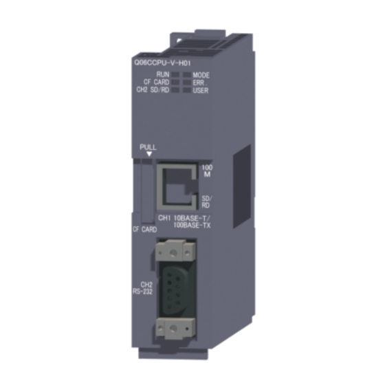
4. Parts Names and Functions 4.1 Parts Names and Functions The part names of the C Controller module are shown below. [Front view] [Front cover opened] Q06CCPU -V-H01 MODE ERR. CF CARD CH2 SD/RD USER STOP MODE RESET SEL. PULL CH1 10BASE-T/ 10BASE-T/ 100BASE-TX... - Page 26 Name Description 1) Indicator LEDs Refer to Section 4.2 for the indicator LEDs. Connector used to connect the C Controller 10BASE-T/100BASE module to 10BASE-T/100BASE-TX. -TX interface (The C Controller module determines 10BASE-T connector (RJ45) or 100BASE-TX depending on the target device.) RS-232 interface Connector used to connect the C Controller connector...
-
Page 27: Led Indicator Specifications
4.2 LED Indicator Specifications Q06CCPU -V-H01 MODE ERR. CF CARD USER CH2 SD/RD CH1 10BASE-T/ 100BASE-TX 4.2.1 In normal operation mode (When the MODE LED is lit "green") Change the operation mode by the switch. (Refer to Section 4.3) LED indicator* LED status Description The C Controller module is in the RUN status. -
Page 28: In Hardware Self-Diagnostic Operation Mode (When The Mode Led Is Lit "Orange")
4.2.2 In hardware self-diagnostic operation mode (When the MODE LED is lit "orange") For the hardware self-diagnostic function, refer to the C Controller Module User’s Manual. Change the operation mode by the switch. (Refer to Section 4.3) Name Description indicator status Hardware self-diagnostic mode MODE... -
Page 29: Switch Operation
4.3 Switch Operation 4.3.1 RUN/STOP/MODE switch operation STOP MODE Position Operation The C Controller module is operating. In normal operation mode (Output (Y) from user program and writing to buffer memory are enabled) In hardware For the hardware self-diagnostic self-diagnostic operation function, refer to the C Controller mode Module User’s Manual. -
Page 30: Reset/Select Switch Operation
4.3.2 RESET/SELECT switch operation RESET SEL. Position Operation When holding All LEDs turn off and the hardware is reset. * RESET position Reset is canceled. The module starts up in either of the following operation modes depending on the RUN/STOP/MODE switch position. When returning RESET 1) In the case of the RUN/STOP position, the module... -
Page 31: External Wiring
5. External wiring 5.1 10BASE-T/100BASE-TX Connection Sufficient safety precautions must be taken when installing the 100BASE-TX and 10BASE-T networks. Consult a specialist when connecting cable terminals or installing trunk line cables, etc. (1) Twisted pair cable Twisted pair cables are used for connection to 10BASE-T/100BASE-TX interfaces. -
Page 32: Rs-232 Connection
5.2 RS-232 Connection RS-232 cables are used for connection to RS-232 interfaces. (1) RS-232 connector specifications Signal direction Signal Signal name C Controller abbreviation Modem module CD(DCD) Data Carrier Detect RD(RXD) Received Data SD(TXD) Transmitted Data ER(DTR) Data Terminal Ready SG(GND) Signal Ground DR(DSR) - Page 33 (4) Precautions for wiring RS-232 cables Precautions for wiring RS-232 cables are shown below. (a) Ground the RS-232 Cable shield to a single point. (b) Use any of the connector shells indicated in (2) on the C Controller module side of the RS-232 cable. (c) Connect the external device according to its specifications.
-
Page 34: External Dimensions
6. External Dimensions Q06CCPU -V-H01 MODE ERR. CF CARD USER CH2 SD/RD PULL 10BASE-T/ 100BASE-TX CF CARD RS-232 27.4 (1.08) 89.3 (3.52) (0.21) STOP MODE RESET SEL. Cable's outside diameter CH1 10BASE-T/ 4 10 100BASE-TX CF CARD RS-232 (Unit: mm (in.)) *1 The bending radius near the connectors (reference value: R1) should be four times as long as the cable's outside diameter or more when connecting the twisted pair cable. -
Page 35: Transportation Precautions
7. Transportation Precautions When transporting lithium batteries, be sure to treat them based on the transportation regulations. 7.1 Applicable Model The lithium battery used for the C Controller module is classified as shown in the table below. Product name Model name Description Handled as Battery for Q series... - Page 36 Ethernet is a trademark of Xerox Corporation. CompactFlash is a trademark of SanDisk Corporation. Other company names and product names used in this document are trademarks or registered trademarks of respective owners.
- Page 38 Paraiso, Sao Paulo, SP Brazil Tel : +86-21-6120-0808 Tel : +55-11-5908-8331 Taiwan Setsuyo Enterprise Co., Ltd. Germany Mitsubishi Electric Europe B.V. German 6F No.105 Wu-Kung 3rd.Rd, Wu-Ku Branch Hsiang, Taipei Hsine, Taiwan Gothaer Strasse 8 D-40880 Ratingen, Tel : +886-2-2299-2499...