
Related Manuals for ABB EAN823


Summary of Contents for ABB EAN823
- Page 1 Instructions Power Electronic Units for Field Installation 42 68 822 EN EAN823, EBN853, EBN861 (Contrac) For the Control of Contrac Actuators of the PME, LME, RHD or RSD Series...
-
Page 2: Table Of Contents
EAN823 / EBN853 / EBN861 (Standard) ..9 EAN823 / EBN851 / EBN861 (PROFIBUS DP) 1.3 ID Labels on the Cover ....10... -
Page 3: Application
General Proper Use Power electronics models EAN823, EBN853 and EBN861 are to be used exlusively for triggering elek- trical actuators of the PME120, LME 620, RSD... or RHD... series. Do not use them for any other pur- pose. Otherwise, a hazard of personal injury or of damage to or impairment of the operational reliability of the device may arise. -
Page 4: Assemblies
Power electronics EAN823, EBN853 and EBN861 consist of 2 parts each, one containing the connect- ing units (EAN823 and EBN853) and the transformer, the other containing the electronics and the local control panel (LCP) for local operation and adjustment of the actuator. -
Page 5: Ebn861
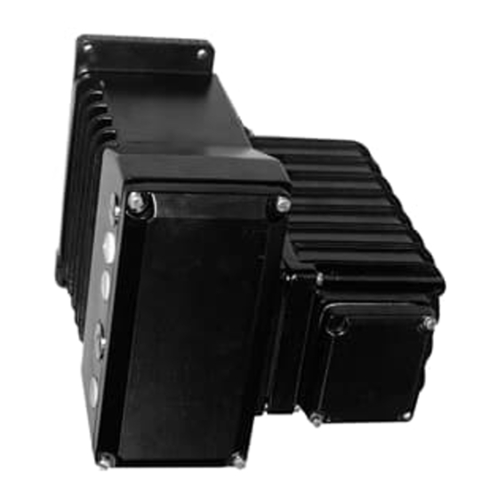
EBN861 local control panel (LCP) cover screws hinge screws transformer and power part hinge screws cover screws signal cable signal terminals power mains cable elctronic unit cable cable entry cover entry terminals (motor) motor / brake Fig. 4: EBN861 without LCP and connection chamber cover... -
Page 6: Technical Data
2 m... 100 m (max.) Weight approx. 10 kg approx. 11 kg approx. 42 kg Table 1 Not available for communication via PROFIBUS DP Current Consumption of EAN823 115 V 230 V pos. PME 120 AN 1.0 A 0.55 A each around 40 ... -
Page 7: Current Consumption Of Ebn853
13.0 Table 4 Fuses Electronic Fuse type Mounting site U = 115 V U = 230 V unit EAN823 External fuse external 16 A, slow Mains fuse in connection chamber 6.3 A, slow 3.15 A, slow Analogue setpoint input in connection chamber 40 mA;... -
Page 8: Mounting
- The shield of the connection cable between the electronics and the actuator must be applied to both housings. Mounting of EAN823 / EBN853 Disconnect the electronics and the actuator prior to all installation and service works. - Fasten the unit to the vertical mounting plate, using screws of property class 8.8 (tensile strength 800 N/mm ;... -
Page 9: Electrical Connection
6 W (Option) Contrac Actuator motor brake r00350x1 Fig. 8: max 50W with EAN823 and actuator for temperature range -25° ... +55°C EAN823 / EBN851 / EBN861 (PROFIBUS DP) mains supply ext. fuse AC115 / 230 V EBN861: Bus in... -
Page 10: Connecting The Cable Shield
Fig. 10: Connecting the cable shield of EAN823; EBN853; EBN861 Screen connection at the actuator ist done accordingly. Example for signal input / output (conventional analogue / binary control) -
Page 11: Cable Guidance At The Plug
Cable guidance at the plug Pass and connect both the signal and the power cable separately within the plug housing in order to avoid electro magnetic interferences. A metal plate separates both cable areas from eachother. Con- nect the screen acc. to fig. 13. Leistungskabel Signal- kabel... -
Page 12: Setup
13.Setup The actuator only requires the basic settings (adaptation to the operating range) in order to be operated with the standard or custumer specific configuration. Use the Local Control Panel (LCP) for these set- tings. Use the appropriate configuration software for more detailed parameter changes or diagnosis functions. -
Page 13: Adjustment Using The Configuration Program
13.1.4Setting 13.1.4.1 “Setting” mode - Set electronics to “setting” mode by pressing both push buttons (3) simultaneously for approx. 5 seconds, until both LEDs (2 + 8) are flashing synchronously at approx. 4Hz. („setting mode“ is the standard electronic unit status after passing the final factory test) 13.1.4.2 Defining first position (0% or 100%) (Higher precision in 2nd position) - Move to desired position by pressing one of the push buttons (3). -
Page 14: Alarms / Failures
14. Alarms / Failures 14.1 Definition 14.1.1 Alarms The actuator / electronic unit is exposed to critical conditions (e. g. high temperature) which currently do not affect the actuator, the electronic unit, the process or persons. The actuator functions are still available. -
Page 15: Failure Scheme
14.3 Failure scheme positioning loop hardware monitoring software monitoring monitoring frequency converter position sensor memory error - standstill end position flash error - min. speed RAM error - movem. to wrong direct. watchdog monitoring activated monitoring & Failure Signal failure message via act. -
Page 16: Troubleshooting
15. Troubleshooting This section mainly describes how to handle hardware errors. Refer to the configuration program’s on- line help for errors related to the software. Error Possible reason Measures to be taken Valve cannot be moved by actuator Malfunction of actuator or valve (e.g. Disconnect the actuator from the stuffing box tightened too much) valve. - Page 17 ABB has Sales & Customer Support The Company’s policy is one of continuous product expertise in over 100 countries worldwide.. improvement and the right is reserved to modify the information contained herein without notice. www.abb.com/instrumentation Printed in the Fed. Rep. of Germany (08.05) ©...