Advertisement
POLARIS
®
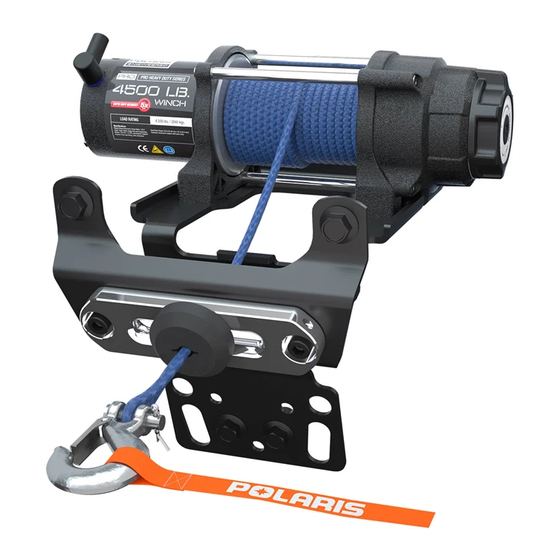
PRO HD 4500 WINCH KIT
P/N 2882240
APPLICATION
Verify accessory fitment at Polaris.com.
You must order below mentioned power cable kit
separately to connect battery to the vehicle bus bar.
• MY14/15 2 Seat Models - PN 2879862
• MY14/15 4 Seat Models - PN 2880055
• MY16 2 Seat Models - PN 2881551
• MY16 4 Seat Models - PN 2881646
MY17 RZR Turbo comes with pre-wired for winch
installation. No additional power cable kit is required.
BEFORE YOU BEGIN
Read these instructions and check to be sure all parts and tools are accounted for. Please retain these
installation instructions for future reference and parts ordering information.
NOTE
NOTE
Instr 9927473
Rev 01 2016-12
Page 1 of 13
Advertisement
Table of Contents

Related Manuals for Polaris PRO HD 4500 WINCH KIT


Summary of Contents for Polaris PRO HD 4500 WINCH KIT
- Page 1 POLARIS ® PRO HD 4500 WINCH KIT P/N 2882240 APPLICATION Verify accessory fitment at Polaris.com. NOTE You must order below mentioned power cable kit separately to connect battery to the vehicle bus bar. • MY14/15 2 Seat Models - PN 2879862 •...
-
Page 2: Kit Contents
KIT CONTENTS This Kit includes: PART DESCRIPTION PART NUMBER Winch Cable, Yellow 6 GA 4013468-480 Winch Cable, Blue 6 GA 4013469-400 Power Cable, Black 4013470-375 Power Cable, Red 4013471-375 Winch Assembly, 4500 HDDS 2206382 Latch Hook 2411836 Control Box Rope 2879187 Wireless Remote Kit 2879316... -
Page 3: Tools Required
PART DESCRIPTION PART NUMBER Screw - Hex Flange - M8 X 1.25 X 20 Screw - Hex Flange - M6 X 35 Screw - M10 X 1.5 X 25 Nut - M10 X 1.5 Nut - Hex Flange - M12 X 1.75 Winching Guide 9923644 Instructions... - Page 4 Your POLARIS ® PRO HD 4500 WINCH KIT is exclusively designed for your vehicle. Please read the installation instructions thoroughly before beginning. Installation is easier if the vehicle is clean and free of debris. For your safety, and to ensure a satisfactory installation, perform all installation steps correctly in the sequence shown.
- Page 5 6. Remove the center console by removing two 9. Remove front fascia by removing six screws screws and five push darts supporting to radiator shroud and ten screws supporting to chassis and body panels. 7. Remove the plastic winch cover by removing two screws .
-
Page 6: Winch Installation
2. Install red and black cables from power cable kit TORQUE to vehicle bus bar as shown. 4ft. lbs. (5.4 Nm) WINCH INSTALLATION 3. Slide winch assembly from left to right and 1. Align and install winch mounting bracket install onto the mounting bracket by aligning chassis bracket and front suspension bracket... - Page 7 6. Feed the winch rope through fairlead mounting TORQUE bracket , autostop fairlead , and rubber stop 16ft. lbs. (21.7 Nm) as shown. Install winch hook to rope using clevis and cotter pin. HINT: Attach a plastic cable tie to the end of the rope and feed the cable tie through the rubber stop.
-
Page 8: Control Box Installation
2. Route power wires from control box to bus bar and TORQUE connect red positive (+) (or orange depending on 4ft. lbs. (5.4 Nm) the date your accessory kit was built) power wire from control box to orange, keyed power terminal on the vehicles bus bar. -
Page 9: Final Inspection
WIRELESS REMOTE HOLDER INSTALLATION • To use the wireless remote, hold the small "On/Off" button for three seconds or until the LED light on the 1. Wireless remote holder can be installed in desired remote turns on. If the vehicle is on so that the location on vehicle. -
Page 10: Gear Selection
During final inspection, confirm that the Autostop is To shift into low, rotate the gear shifting knob counter- functioning properly. See the troubleshooting section clockwise until the “L” marking shows thru the cutout to help diagnose and correct any problems. window on the shift knob. -
Page 11: Troubleshooting
TROUBLESHOOTING If your winch/Autostop is not functioning properly, below is a short guide that can help you diagnose and correct the problem. SYMPTOM POSSIBLE CAUSES RECOMMENDED SOLUTION Dead Vehicle Battery Check that all power wires are Rewire to ensure wiring is connected to the correct terminals connected properly per instructions. - Page 12 SYMPTOM POSSIBLE CAUSES RECOMMENDED SOLUTION Winch makes noise but rope does Winch not in proper gear Rotate gear knob fully into L or H, not move then recheck. Winch operates too slowly Winch in wrong gear Rotate gear knob into proper gear, then recheck.
-
Page 13: Feedback Form
ELECTRICAL CONNECTION REFERENCE GUIDE Winch with auto fairlead and wireless remote FEEDBACK FORM A feedback form has been created for the installer to provide any comments, questions FEEDBACK FORM or concerns about the installation instructions. The form is viewable on mobile devices by scanning the QR code or by clicking HERE if viewing on a PC.
Need help?
Do you have a question about the PRO HD 4500 WINCH KIT and is the answer not in the manual?
Questions and answers