Table of Contents
Advertisement
Quick Links
SPORTSMAN
WINCH KIT
P/N 2882241
APPLICATION
Verify accessory fitment at Polaris.com.
BEFORE YOU BEGIN
Read these instructions and check to be sure all parts and tools are accounted for.
Please retain these installation instructions for future reference and parts ordering
information.
KIT CONTENTS
This Kit includes:
REF
QTY
PART DESCRIPTION
1
1
Handlebar Switch
2
1
Control Box
3
1
Wireless Remote Kit
4*
5
Panduit Strap
4
5*
Screw, Hex Flange - M8 X 1.25 X 25
6
1
Mounting Bracket
7
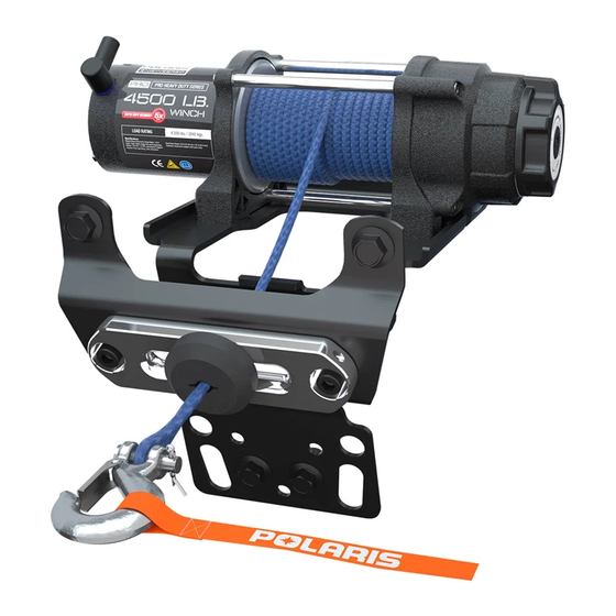
1
Winch - 35 HDDS
8
1
Hook, Winch Latch
®
XP POLARIS
Instr 9927474
®
PRO HD
Rev 01 2017-02
Page 1 of 14
PART NUMBER
2205636
2413444
2879316
-
-
1022577
2206383
2411836
Advertisement
Table of Contents

Related Manuals for Polaris PRO HD


Summary of Contents for Polaris PRO HD
- Page 1 PRO HD WINCH KIT P/N 2882241 APPLICATION Verify accessory fitment at Polaris.com. BEFORE YOU BEGIN Read these instructions and check to be sure all parts and tools are accounted for. Please retain these installation instructions for future reference and parts ordering information.
-
Page 2: Tools Required
XP POLARIS ® PRO HD WINCH KIT is exclusively designed for your vehicle. Please read the installation instructions thoroughly before beginning. Installation is easier if the vehicle is clean and free of debris. For your safety, and to ensure a satisfactory installation, perform all installation steps correctly in the sequence shown. -
Page 3: Installation Instructions
INSTALLATION INSTRUCTIONS NOTE This kit contains the same components as Sportsman (non-XP) winch kit (PN 2882242), but have been pre-assembled differently. If you need to install this kit on a Sportsman (non-XP) vehicle, refer to image below that shows the contactor location and wire routing for Sportsman (non-XP) winch kit, and reassemble the contactor and wiring to match below image. -
Page 4: Winch Installation
5. Remove the accessory front brushguard from vehicle (if equipped). 6. Remove the lower front bumper cover removing four bolts . Retain bolts for use during reinstallation. NOTE Before installing the winch kit add or replace the proper front gearcase fluid as required per your vehicles service manual as this process will be difficult to do after the winch is installed. - Page 5 2. Install winch assembly to chassis frame 4. Locate the vehicles main harness winch contactor using four screws as shown. Check that all connection on the frame tube of the vehicle behind wires are free to move and not pinched between the front left tire as seen in the photo below.
-
Page 6: Control Box Installation
CONTROL BOX INSTALLATION WIRELESS REMOTE RECEIVER INSTALLATION 1. Position control box on the left side of the vehicle 1. Mount wireless remote receiver onto cab behind the radiator as seen in the photo below. support bracket using provided cable ties as Connect white electrical connectors for the control shown. -
Page 7: Final Inspection
WIRELESS REMOTE HOLDER INSTALLATION 3. Secure all remaining wires to the vehicles main wire harness as shown. 1. Wireless remote holder can be installed in desired location on vehicle. Use the screws provided in the wireless remote kit for holder installation. For your reference see the photo below for possible mounting location of wireless remote holder. - Page 8 REINSTALLATION HANDLEBAR SWITCH OPERATION • When properly installed, the handlebar switch 1. Reinstall the front bumper cover on vehicle allows you to operate the winch while seated on the using retained screws vehicle. See the illustration below for proper switch 2.
-
Page 9: Wireless Remote Operation
WIRELESS REMOTE OPERATION AUTOSTOP OPERATION The Autostop system is meant to help prevent • When properly installed, the wireless remote will damage to the winch system from over-tightening of allow you to operate the winch from off the vehicle, the rope, but is not meant to prevent all foreseeable which can be a safe way to operate the winch when winch damage. - Page 10 RAPID RECOVERY WINCH FUNCTION The high gear setting is meant for rapid recovery mode only and should not be used while the rope is Your winch is equipped to quickly reel in the winch under load. To shift into high gear, rotate the gear rope when being used under no-load conditions.
-
Page 11: Troubleshooting
TROUBLESHOOTING If your winch/Autostop is not functioning properly, below is a short guide that can help you diagnose and correct the problem. SYMPTOM POSSIBLE CAUSES RECOMMENDED SOLUTION Dead Vehicle Battery Check to ensure that both the Rewire to ensure wiring is wireless remote receiver and connected properly per instructions. - Page 12 SYMPTOM POSSIBLE CAUSES RECOMMENDED SOLUTION Winch makes noise but rope does Winch not in proper gear Rotate gear knob fully into L or H, not move then recheck. Winch operates too slowly Winch in wrong gear Rotate gear knob into proper gear, then recheck.
- Page 13 ELECTRICAL CONNECTIONS REFERENCE GUIDE Winch with auto fairlead, wireless remote, and handle bar switch Winch with auto fairlead and handle bar switch Winch with roller fairlead and handle bar switch Instr 9927474 Rev 01 2017-02 Page 13 of 14...
-
Page 14: Feedback Form
9927474 FEEDBACK FORM A feedback form has been created for the installer to provide any comments, questions FEEDBACK FORM or concerns about the installation instructions. The form is viewable on mobile devices by scanning the QR code or by clicking HERE if viewing on a PC.