Table of Contents
Advertisement
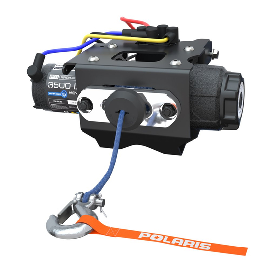
WINCH 3500 AND 4500 KIT
P/N 2879461; 2879462
Application
RZR XP 1000
Before you begin, read these instructions twice and check to be sure all parts and tools are accounted for. Please
retain these installation instructions for future reference and parts ordering information.
13
3
2
3500 Winch Kit Contents:
Ref
Qty
1
1
2
1
3
1
4
1
5
1
6
1
7
1
8
1
9
1
10
1
11
1
12
1
13
1
14
1
15*
2
16*
2
17*
4
18*
6
19*
4
10
8
9
12
Part Description
Winch-Polaris, 3.5
Hook-Latch, Winch
Roller-Fairlead, Winch 25/3500
Cable-Winch, Steel, 3/16"
Contactor-Winch
Remote-Switch, Winch
Socket-Winch
Cable-Winch, Yellow 6 GA, 480mm
Cable-Winch, Blue 6 GA, 400mm
Power Cable, Winch, Black 6 GA, 375mm
Power Cable, Winch, Red 6 GA, 375mm
Power Bracket, Winch, Red RZN
Fairlead Bracket Mount, RZN
Cable-Assembly, Battery to Terminal Block
Screw-M5x0.8X208.8TXPH ZOD
Nut-M5X0.8X8.8 HX/FL NYLOC
Screw-HXFL-M6X35 ZOD HILO
Nut-M10X1.5 HFN NYLOC-ZOD
Nut-M12X1.75, FLG, NYLOC-OLIVE D
11
6
7
5
1
4
-1-
14
Part Number
2204688
2411836
2411848
2878890
4013465
4013466
4014228
4013468-480
4013469-400
4013470-375
4013471-375
5257962
5257963
4014577
7518980
7547427
7519330
7547423
7547441
Advertisement
Table of Contents

Related Manuals for Polaris 3500


Summary of Contents for Polaris 3500
- Page 1 WINCH 3500 AND 4500 KIT P/N 2879461; 2879462 Application RZR XP 1000 Before you begin, read these instructions twice and check to be sure all parts and tools are accounted for. Please retain these installation instructions for future reference and parts ordering information.
- Page 2 Service Kit Handle, HD Winch 2205265 Item marked (*) are included in Hardware Kit PN 2205119. 4500 Winch Kit Contents: Part Description Part Number Winch-Polaris, 4.5, BTM SPL 2204855 Hook-Latch, Winch 2411836 Fairlead, HAWSE, MACH, WIDE 2879148 Stop-Magnet, Bumper, Rubber...
- Page 3 1 1/6” Hole Saw or Drill APPROXIMATE ASSEMBLY TIME: 45 minutes IMPORTANT: Your Polaris RZR XP 1000 WINCH 3500 and 4500 is exclusively designed for your vehicle. Please read the installation instructions thoroughly before beginning. Installation is easier if the vehicle is clean and free of debris. For your safety, and to ensure a satisfactory installation, perform all installation steps correctly in the sequence shown.
- Page 4 INSTALLATION INSTRUCTIONS 1. Place the vehicle in “PARK” and turn the key to “OFF” position. Remove the key from the vehicle. Battery Cables Remove the driver seat. Disconnect the black Under Seat negative and the red positive battery cable from the battery.
- Page 5 4. After removing shift lever cap and shift handle, take Screw off the center console by removing the two screws (PN 7519650) and the four tuff lock rivets (PN 7661855). Figure 4. Lift Figure 4 5. Route the cable (PN 4014577) having red and black wires from bus bar to the battery.
- Page 6 6. Detach the plastic plate by removing two screws (PN 7518980). Figure 6. Screw Figure 6 7. Take off the front fascia by removing six hexagonal Screw screws (PN 7518529) and four screws (PN 7519650). Figure 7. Hexagonal Screw Figure 7 8.
- Page 7 9. Connect the wires to the winch before installing it onto the vehicle. Figure 9. Yellow Wire Blue Wire NOTE: Connect blue wire to the blue terminal and yellow wire to the yellow terminal (color coding is already provided on winch). Figure 9. Figure 9 10.
- Page 8 12. Lead mounting: Front Plate Bracket a) For 3500 Winch: Mount the roller fair lead (PN 2411848) onto the front plate bracket Roller (PN 5257963) with two screws (PN 7519372) and Fair Lead nuts (PN 7547423). Figure 12. b) For 4500 Winch: Mount the fair lead (PN 2879148)
- Page 9 14. Cable installation: a) For 3500 Winch: Twist the knob on the winch (PN 2204688) and insert the cable through front plate bracket (PN 5257963) and roller fair lead (PN 2411848) to move the cable freely. Figure 16. Knob b) For 4500 Winch: Twist the knob on the winch...
- Page 10 15. Hook attachment: a) For 3500 and 4500 Winch: Attach the hook (PN 2411836) with the cable by inserting the clip Attachment through it. Figure 18 and Figure 19. Point to Vehicle Hook Figure 18 Attachment Point to Vehicle Hook...
- Page 11 16. Mount the winch contactor (PN 4013465) on the firewall with the four bolts (PN 7519330) at the specified drilled holes. Figure 20. NOTE: Ensure that the yellow color code on the contactor is on top. Bolt Figure 20 17. Connect the blue (PN 4013469), yellow (PN 4013468), red (PN 4013471) and black wires (PN 4013470) to the contactor terminals and put the caps.
- Page 12 Socket Wire the grommet in the firewall. Figure 23. NOTE: Socket position may change as per requirement. Figure 23 For 3500 Winch 20. Plug in the socket wire connector to the contactor Firewall connector (PN 4013465). Figure 24. Grommet Contactor Figure 24 21.
- Page 13 For 4500 Winch 22. Connect the connector from fairlead to auto stop Fairlead control unit connector. Figure 26. Connector Control Unit Connector Figure 26 23. Route the wire from fairlead to the auto-stop control Auto-stop unit. Figure 27. Control Unit NOTE: Use panduit straps to secure the cable from Cable hot or moving parts.
- Page 14 Auto-stop Figure 30 Connector Control Unit For 3500 and 4500 Winch Kits: Hole 27. Cut out a hole in the din box for mounting the socket (PN 4014228). Figure 31. NOTE: Follow the instruction on the back of the din for the cutout.
- Page 15 28. Drill the mounting holes to the specified location around the cut out of the socket on the back of din box. Figure 32. NOTE: Use 1/4” drill bit. Mounting hole in socket Hole in din box Figure 32 29. Attach socket (PN 4014228) onto the din box with two bolts (PN 7518980) and two nuts (PN 7547427), at specified position.
Need help?
Do you have a question about the 3500 and is the answer not in the manual?
Questions and answers
My Polaris 3500 winch is attached to a snow plow. The control stick for up and side to side all work. The winch will not lower when I use the button?
The context does not provide a direct answer to why the Polaris 3500 winch won't lower when using the button. However, potential issues could include a malfunctioning switch, wiring problems, or mechanical resistance in the winch mechanism. Some users reported resistance when disengaging the winch, which may indicate a mechanical issue. Checking the wiring, switch functionality, and ensuring proper disengagement may help diagnose the problem.
This answer is automatically generated