Huawei OceanStor 2600 V3 Product Description
Hide thumbs
Also See for OceanStor 2600 V3:
- Quick configuration manual (16 pages) ,
- Features manual (196 pages) ,
- Features manual (160 pages)

Related Manuals for Huawei OceanStor 2600 V3


Summary of Contents for Huawei OceanStor 2600 V3
- Page 1 OceanStor 2600 V3 V300R006 Product Description Issue Date 2019-05-15 HUAWEI TECHNOLOGIES CO., LTD.
- Page 2 Notice The purchased products, services and features are stipulated by the contract made between Huawei and the customer. All or part of the products, services and features described in this document may not be within the purchase scope or the usage scope. Unless otherwise specified in the contract, all statements, information, and recommendations in this document are provided "AS IS"...
-
Page 3: About This Document
About This Document Purpose This document describes the orientation, features, architecture, technical specifications, product configuration, environment requirements, standards compliance and granted certifications of the OceanStor 2600 V3 storage system. Intended Audience This document is intended for: All readers Symbol Conventions The symbols that may be found in this document are defined as follows. - Page 4 This issue is the fourth official release. The updates are as follows: Made minor changes in specifications. Issue 03 (2017-08-30) This issue is the third official release. The updates are as follows: Made some changes in specifications. Issue 09 (2019-05-15) Copyright © Huawei Technologies Co., Ltd.
- Page 5 About This Document Issue 02 (2017-06-01) This issue is the second official release. The updates are as follows: Made minor changes in specifications. Issue 01 (2017-02-28) This issue is the first official release. Issue 09 (2019-05-15) Copyright © Huawei Technologies Co., Ltd.
-
Page 6: Table Of Contents
4.3.1 Overview................................... 50 4.3.2 Component Description............................. 52 4.3.2.1 System Subrack..............................52 4.3.2.2 Expansion Module..............................52 4.3.2.3 Power Module.................................54 4.3.2.4 Disk Module................................57 4.3.3 Indicator Introduction..............................58 4.4 4 U Disk Enclosure (3.5-Inch Disks)..........................61 Issue 09 (2019-05-15) Copyright © Huawei Technologies Co., Ltd. - Page 7 6 Product Specifications......................115 6.1 Hardware Specifications............................. 115 6.2 Software Specifications.............................. 122 7 Environmental Requirements....................135 7.1 Temperature, Humidity, and Altitude......................... 135 7.2 Vibration and Shock..............................136 7.3 Particle Contaminants..............................137 7.4 Corrosive Airborne Contaminants..........................138 Issue 09 (2019-05-15) Copyright © Huawei Technologies Co., Ltd.
- Page 8 A.1.2 Making Debugging Preparations..........................153 A.2 How to Use the Document............................153 A.3 How to Obtain Help from Website..........................154 A.4 Ways to Contact Huawei............................154 B Glossary............................155 C Acronyms and Abbreviations....................156 Issue 09 (2019-05-15) Copyright © Huawei Technologies Co., Ltd.
-
Page 9: Product Positioning
On a Unified SAN and NAS Network Figure 1-1 shows the position and application of the OceanStor 2600 V3 storage system on a unified SAN and NAS network. Issue 09 (2019-05-15) - Page 10 OceanStor 2600 V3 Product Description 1 Product Positioning Figure 1-1 Position and application Issue 09 (2019-05-15) Copyright © Huawei Technologies Co., Ltd.
-
Page 11: Product Features
In addition, SmartTier supports solid state drive (SSD) data caching, accelerating access to hotspot data. SSDs The OceanStor 2600 V3 storage system can be fully configured with SSDs to provide peak performance for the most-demanding applications. Flexible Scalability The OceanStor 2600 V3 storage system has an outstanding scalability. - Page 12 SmartIO interface modules support various port types including 8 Gbit/s Fibre Channel, 16 Gbit/s Fibre Channel, 10 Gbit/s FCoE (VN2VF), 10 Gbit/s Ethernet, and iWARP (interconnection between Scale-out nodes). The OceanStor 2600 V3 storage system also supports Scale-out expansion of clustered nodes for system performance improvement. Proven Reliability The OceanStor 2600 V3 storage system uses advanced technologies to offer protection measures, minimizing risks of failures and data loss.
- Page 13 High Availability In routine maintenance: The OceanStor 2600 V3 storage system uses Turbo Module, online capacity expansion, and disk roaming technologies to provide high availability for applications and nonstop system running during maintenance. Turbo Module enables controllers, fans, power modules, interface modules, and disks to be hot-swappable, allowing online operations.
- Page 14 SmartMulti-Tenant enables a storage system to provide different tenants with shared storage resources and to separate tenant access and management. The OceanStor 2600 V3 storage system supports memory upgrade so that storage performance matches service development. High System Security...
- Page 15 Virtualization, Intelligence, and Efficiency The OceanStor 2600 V3 storage system absorbs the concept of "Virtualization, Intelligence, and Efficiency", which fits the up-to-date storage design idea and wins a leading position for the storage system. Compared with traditional storage systems, the storage system introduces...
- Page 16 Cost-Effectiveness and Ease-of-Use The OceanStor 2600 V3 storage system delivers cost-effective performance through intelligent CPU frequency control, delicate fan speed control, deduplication, and compression. It also provides a series of management and maintenance tools for easy use and maintenance.
- Page 17 Provides alarm notification by sound, indicator, short message service (SMS), or email. – Tool for an upgrade at your fingertip Provides one-click online upgrade for controllers. The operation is easy without interrupting services. Issue 09 (2019-05-15) Copyright © Huawei Technologies Co., Ltd.
-
Page 18: Typical Applications
3.3 High-Density and Multi-Service Applications 3.1 High-Performance Applications The OceanStor 2600 V3 storage system incorporates various technologies to boost the system performance. Its high-performance hardware delivers outstanding data access performance. The virtualization technology can improve the storage performance continuously and it shatters performance bottlenecks from future business growth. - Page 19 Traditional storage systems cannot address such a storage requirement. The OceanStor 2600 V3 storage system uses the intelligent data tiering technology, SmartTier, to identify hotspot data and promote it to high-performance SAS disks or SSDs. If SmartTier later finds out that the hotspot data becomes cold (receiving fewer access requests), it demotes the data to low-performance disks and clears storage space for new hotspot data.
-
Page 20: High-Availability Applications
3 Typical Applications 3.2 High-Availability Applications The OceanStor 2600 V3 storage system has a highly reliable design, achieving a long mean time between failures (MTBF), and ensuring high availability of storage applications. It also incorporates a variety of data protection technologies, and protects data integrity and service continuity against catastrophic disasters. - Page 21 Resilience Against Disasters The OceanStor 2600 V3 storage system compliments various data protection methods for backup and disaster recovery. Those methods eliminate the risks of unexpected downtime and data loss caused by natural disasters, serious device failures, or man-made misoperations.
-
Page 22: High-Density And Multi-Service Applications
The OceanStor 2600 V3 storage system delivers industry-leading density of interface modules in an enclosure and a flexible configuration of interface modules and disks of different types. This design makes the OceanStor 2600 V3 storage system suitable for high-density and multi- service applications. - Page 23 Backup servers have low requirements on performance and bandwidths. The OceanStor 2600 V3 storage system supports an intermixed configuration of SSDs, SAS disks, and NL-SAS disks to deliver optimal performance. SSDs: deliver the highest performance among these three types of disk, and are suitable for application servers such as busy database servers and mail servers that require superior storage performance.
-
Page 24: Hardware Architecture
Different product models use different types of controller enclosures and disk enclosures. Table 4-1 lists the controller enclosures and disk enclosures used by different product models. Issue 09 (2019-05-15) Copyright © Huawei Technologies Co., Ltd. - Page 25 Figure 4-1 2 U controller enclosure with 12 disk slots Figure 4-2 2 U controller enclosure with 25 disk slots Figure 4-3 2 U disk enclosure with 25 disk slots Figure 4-4 4 U disk enclosure with 24 disk slots Issue 09 (2019-05-15) Copyright © Huawei Technologies Co., Ltd.
-
Page 26: Controller Enclosure
The controller enclosure adopts a modular design and consists of a system subrack, controllers, power modules, and disk modules. The 2 U controller enclosure of OceanStor 2600 V3 supports both AC and DC power modules, and a 2 U controller enclosure of OceanStor 2600 V3 supports dual controllers only. - Page 27 Figure 4-6 Overall structure of a 2 U 25-disk controller enclosure System subrack Disk module Power module Controller Figure 4-7 Overall structure of a 2 U 12-disk controller enclosure System subrack Disk module Power module Controller Issue 09 (2019-05-15) Copyright © Huawei Technologies Co., Ltd.
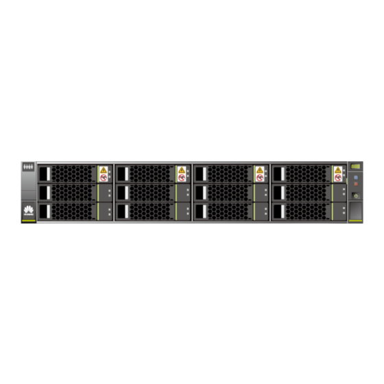
- Page 28 Figure 4-9 Front view of a 2 U 12-disk controller enclosure Disk module handle Coffer disk label Information plate ID display of the (with ESN) controller enclosure Power indicator/ Disk module latch Power button Issue 09 (2019-05-15) Copyright © Huawei Technologies Co., Ltd.
- Page 29 OceanStor 2600 V3 provides onboard GE and mini SAS HD expansion ports. l The controller enclosure of OceanStor 2600 V3 supports 8 Gbit/s Fibre Channel interface modules (four ports), GE electrical interface modules, 10GE electrical interface modules, SmartIO interface modules, and 8 Gbit/s Fibre Channel interface modules (eight ports).
-
Page 30: Component Description
OceanStor 2600 V3 Product Description 4 Hardware Architecture Figure 4-11 Rear view of the OceanStor 2600 V3 controller enclosure (with AC power modules and dual controllers) Power module Power module handle Power module latch GE electrical port Interface module SmartIO port... -
Page 31: Controller
OceanStor OS data. The disks in controller and those in another are redundant for each other. Appearance Each controller supports two interface modules. Figure 4-13 shows the appearance of a controller. Issue 09 (2019-05-15) Copyright © Huawei Technologies Co., Ltd. - Page 32 Figure 4-14 Ports of a controller Controller handle GE electrical port Interface module Link/Active/Mode handle indicator of the SmartIO port SmartIO port Power indicator of the interface module/Hot Swap button of the module Issue 09 (2019-05-15) Copyright © Huawei Technologies Co., Ltd.
- Page 33 GE port electrical port Speed indicator of the GE electrical port Indicators Table 4-2 describes the states and corresponding meanings of indicators on a controller after it is powered on. Issue 09 (2019-05-15) Copyright © Huawei Technologies Co., Ltd.
- Page 34 Blinking green (1 Hz): The backup power module is being charged. l Blinking green (4 Hz): The backup power module is being discharged. l Steady red: The backup power module is faulty. Issue 09 (2019-05-15) Copyright © Huawei Technologies Co., Ltd.
-
Page 35: Power Module
The controller enclosure supports both AC and DC power modules. Appearance Figure 4-15 Figure 4-16 show the front view of an AC power module and a DC power module respectively. Issue 09 (2019-05-15) Copyright © Huawei Technologies Co., Ltd. - Page 36 4 Hardware Architecture Figure 4-15 Front view of an AC power module Fan built in the Power module power module handle Power module latch Power module socket Running/Alarm indicator of the power module Issue 09 (2019-05-15) Copyright © Huawei Technologies Co., Ltd.
- Page 37 Green blinking: The power input is normal but the enclosure is powered off. l Steady red: The power supply is faulty. l Off: No external power input is found. Issue 09 (2019-05-15) Copyright © Huawei Technologies Co., Ltd.
-
Page 38: Disk Module
Appearance Figure 4-17 shows the appearance of a 2.5-inch disk module. Figure 4-18 shows the appearance of a 3.5-inch disk module. Figure 4-17 2.5-inch disk module Issue 09 (2019-05-15) Copyright © Huawei Technologies Co., Ltd. - Page 39 Steady green: The disk module is the disk module working correctly. l Blinking green: Data is being read and written on the disk module. l Off: The disk module is powered off or powered on incorrectly. Issue 09 (2019-05-15) Copyright © Huawei Technologies Co., Ltd.
-
Page 40: Gbit/S Fibre Channel Interface Module (Four Ports)
Figure 4-19 8 Gbit/s Fibre Channel interface module (four ports) Power indicator/Hot 8 Gbit/s Fibre Swap button on the Channel port module Link/Speed indicator Module handle of an 8 Gbit/s Fibre Channel port Issue 09 (2019-05-15) Copyright © Huawei Technologies Co., Ltd. -
Page 41: Gbit/S Fibre Channel Interface Module (Eight Ports)
Interface Figure 4-20 shows the appearance of an 8 Gbit/s Fibre Channel interface module (eight ports). Issue 09 (2019-05-15) Copyright © Huawei Technologies Co., Ltd. - Page 42 Blinking green: The interface module receives a hot swap request. l Steady red: The interface module is faulty. l Off: The interface module is powered off or can be hot-swappable. Issue 09 (2019-05-15) Copyright © Huawei Technologies Co., Ltd.
-
Page 43: Ge Electrical Interface Module
A GE electrical interface module has four 1 Gbit/s electrical ports. Ports Figure 4-21 shows the appearance of a GE electrical interface module. Figure 4-21 GE electrical interface module Power indicator/Hot GE electrical port Swap button on the interface module Issue 09 (2019-05-15) Copyright © Huawei Technologies Co., Ltd. -
Page 44: 10Ge Electrical Interface Module
A 10GE electrical interface module has four 10 Gbit/s electrical ports. Ports Figure 4-22 shows the appearance of a 10GE electrical interface module. 10GE electrical interface modules of the storage system support GE/10GE autonegotiation. Issue 09 (2019-05-15) Copyright © Huawei Technologies Co., Ltd. - Page 45 Blinking green: There is a hot swap request to the module. l Steady red: The module is faulty. l Off: The module is powered off or hot swappable. Issue 09 (2019-05-15) Copyright © Huawei Technologies Co., Ltd.
-
Page 46: Smartio Interface Module
Figure 4-23 SmartIO interface module Figure 4-24, Figure 4-25, Figure 4-26, Figure 4-27, and Figure 4-28 show 8 Gbit/s, 10 Gbit/s, and 16 Gbit/s, 25 Gbit/s, and 32 Gbit/s SmartIO interface modules respectively. Issue 09 (2019-05-15) Copyright © Huawei Technologies Co., Ltd. - Page 47 OceanStor 2600 V3 Product Description 4 Hardware Architecture Figure 4-24 8 Gbit/s SmartIO interface module Figure 4-25 10 Gbit/s SmartIO interface module Issue 09 (2019-05-15) Copyright © Huawei Technologies Co., Ltd.
- Page 48 OceanStor 2600 V3 Product Description 4 Hardware Architecture Figure 4-26 16 Gbit/s SmartIO interface module Figure 4-27 25 Gbit/s SmartIO interface module Issue 09 (2019-05-15) Copyright © Huawei Technologies Co., Ltd.
- Page 49 Blinking green: There is a hot swap request to the module. l Steady red: The module is faulty. l Off: The interface module is powered off or hot swappable. Issue 09 (2019-05-15) Copyright © Huawei Technologies Co., Ltd.
-
Page 50: Gbit/S Sas Expansion Module (Supported By V300R006C10 And Later)
Ports Figure 4-29 shows the appearance of a 12 Gbit/s SAS expansion module. Issue 09 (2019-05-15) Copyright © Huawei Technologies Co., Ltd. - Page 51 Blinking green: There is a hot swap request to the module. l Steady red: The module is faulty. l Off: The interface module is powered off or hot swappable. Issue 09 (2019-05-15) Copyright © Huawei Technologies Co., Ltd.
-
Page 52: Indicator Introduction
Running indicator of Location/Alarm the disk module indicator of the disk module Location indicator Alarm indicator of of the controller the controller enclosure enclosure Power indicator/ Power button of the controller enclosure Issue 09 (2019-05-15) Copyright © Huawei Technologies Co., Ltd. - Page 53 Off: The disk module is working correctly or hot swappable. System Location indicator of the l Blinking blue: The controller subrack controller enclosure enclosure is being located. l Off: The controller enclosure is not located. Issue 09 (2019-05-15) Copyright © Huawei Technologies Co., Ltd.
- Page 54 Figure 4-32 Indicators on the rear panel of a controller enclosure Power indicator of Link/Active/Mode the interface indicator of the module/Hot Swap SmartIO port button of the module Issue 09 (2019-05-15) Copyright © Huawei Technologies Co., Ltd.
- Page 55 Blinking green: The interface module receives a module/Hot hot swap request. Swap button l Steady red: The interface module is faulty. of the l Off: The interface module is powered off or can module be hot-swappable. Issue 09 (2019-05-15) Copyright © Huawei Technologies Co., Ltd.
- Page 56 Blinking green (1 Hz): The backup power the backup module is being charged. power l Blinking green (4 Hz): The backup power module module is being discharged. l Steady red: The backup power module is faulty. Issue 09 (2019-05-15) Copyright © Huawei Technologies Co., Ltd.
-
Page 57: Disk Enclosure (2.5-Inch Disks)
1 Gbit/s. 4.3 2 U Disk Enclosure (2.5-Inch Disks) This section describes a disk enclosure in terms of its hardware structure, component functions, front and rear views, and indicators. Issue 09 (2019-05-15) Copyright © Huawei Technologies Co., Ltd. -
Page 58: Overview
Figure 4-33 Overall structure of a disk enclosure System subrack Disk module Power module Expansion module Front View Figure 4-34 shows the front view of a disk enclosure. Figure 4-34 Front view of a disk enclosure Issue 09 (2019-05-15) Copyright © Huawei Technologies Co., Ltd. - Page 59 Power module Power module latch Power module Expansion module handle handle Expansion module Serial port Mini SAS HD PRI Mini SAS HD EXP expansion port expansion port Disk enclosure ID display Issue 09 (2019-05-15) Copyright © Huawei Technologies Co., Ltd.
-
Page 60: Component Description
An expansion module provides expansion ports for communication between the disk enclosure and the controller enclosure. Each expansion module provides a PRI expansion port and an EXP expansion port. Appearance Figure 4-38 shows the appearance of an expansion module. Issue 09 (2019-05-15) Copyright © Huawei Technologies Co., Ltd. - Page 61 Mini SAS HD PRI SAS HD expansion expansion port port Mini SAS HD EXP Disk enclosure ID expansion port display Indicators Table 4-13 describes indicators on an expansion module of a powered-on storage system. Issue 09 (2019-05-15) Copyright © Huawei Technologies Co., Ltd.
-
Page 62: Power Module
The storage system supports AC and DC power modules. Power modules can ensure that the disk enclosure works correctly in maximum power consumption mode. Appearance Figure 4-40 shows the appearance of an AC power module. Figure 4-41 shows the appearance of a DC power module. Issue 09 (2019-05-15) Copyright © Huawei Technologies Co., Ltd. - Page 63 Product Description 4 Hardware Architecture Figure 4-40 AC power module Power module Power module latch handle Fan built in the Power module power module socket Running/Alarm indicator of the power/fan module Issue 09 (2019-05-15) Copyright © Huawei Technologies Co., Ltd.
- Page 64 Fan built in the Positive and power module negative terminals of the power module Running/Alarm indicator of the power/fan module Indicators Table 4-14 describes indicators on a power module of a powered-on storage system. Issue 09 (2019-05-15) Copyright © Huawei Technologies Co., Ltd.
-
Page 65: Disk Module
Disk modules provide storage capacity for a storage system. Disk modules can function as system coffer disks to save service data, system data, and cache data. Appearance Figure 4-42 shows the appearance of a disk module. Figure 4-42 Disk module Issue 09 (2019-05-15) Copyright © Huawei Technologies Co., Ltd. -
Page 66: Indicator Introduction
Indicators on the Front Panel Figure 4-43 shows the indicators on the front panel of a disk enclosure. Figure 4-43 Indicators on the front panel of a disk enclosure Issue 09 (2019-05-15) Copyright © Huawei Technologies Co., Ltd. - Page 67 Off: The disk enclosure is working correctly. Power indicator of the disk l Steady green: The disk enclosure enclosure is powered on. l Off: The disk enclosure is powered off. Issue 09 (2019-05-15) Copyright © Huawei Technologies Co., Ltd.
- Page 68 4 x 3 Gbit/s or 4 x 6 Gbit/s. l Steady red: The port is faulty. l Off: The link to the port is down. Issue 09 (2019-05-15) Copyright © Huawei Technologies Co., Ltd.
-
Page 69: Disk Enclosure (3.5-Inch Disks)
A 4 U SAS disk enclosure supports both AC and DC power modules. The following figure uses the AC power module as an example. Figure 4-45 Overall structure of a disk enclosure Issue 09 (2019-05-15) Copyright © Huawei Technologies Co., Ltd. - Page 70 The coffer disks are inserted into slot 0 to slot 3. Rear View Figure 4-47 shows the rear view of a disk enclosure with the DC power module. Figure 4-47 Rear view of a disk enclosure with the DC power module Issue 09 (2019-05-15) Copyright © Huawei Technologies Co., Ltd.
-
Page 71: Component Description
The system subrack houses a midplane to provide reliable connections for interface modules and to distribute power and signals to inner modules. Appearance Figure 4-49 shows the appearance of a system subrack. Issue 09 (2019-05-15) Copyright © Huawei Technologies Co., Ltd. -
Page 72: Expansion Module
An expansion module provides expansion ports for communication between the disk enclosure and the controller enclosure. Each expansion module provides a PRI expansion port and an EXP expansion port. Appearance Figure 4-50 shows the appearance of an expansion module. Issue 09 (2019-05-15) Copyright © Huawei Technologies Co., Ltd. - Page 73 Mini SAS HD PRI SAS HD expansion expansion port port Mini SAS HD EXP Disk enclosure ID expansion port display Indicators Table 4-18 describes indicators on an expansion module of a powered-on storage system. Issue 09 (2019-05-15) Copyright © Huawei Technologies Co., Ltd.
-
Page 74: Power Module
The storage system supports AC and DC power modules. Power modules can ensure that the disk enclosure works correctly in maximum power consumption mode. Appearance Figure 4-52 shows the appearance of an AC power module. Figure 4-53 shows the appearance of a DC power module. Issue 09 (2019-05-15) Copyright © Huawei Technologies Co., Ltd. - Page 75 Product Description 4 Hardware Architecture Figure 4-52 AC power module Power module Power module latch handle Fan built in the Power module power module socket Running/Alarm indicator of the power/fan module Issue 09 (2019-05-15) Copyright © Huawei Technologies Co., Ltd.
- Page 76 Fan built in the Positive and power module negative terminals of the power module Running/Alarm indicator of the power/fan module Indicators Table 4-19 describes indicators on a power module of a powered-on storage system. Issue 09 (2019-05-15) Copyright © Huawei Technologies Co., Ltd.
-
Page 77: Fan Module
Figure 4-54 Fan module Fan module handle Fan module latch Running/Alarm indicator of the fan module Indicators Table 4-20 describes indicators on a fan module of a powered-on storage system. Issue 09 (2019-05-15) Copyright © Huawei Technologies Co., Ltd. -
Page 78: Disk Module
Figure 4-55 Disk module Disk module label Disk module handle Disk module latch Alarm/Location indicator of the disk module Running indicator of Disk tray the disk module Disk Issue 09 (2019-05-15) Copyright © Huawei Technologies Co., Ltd. -
Page 79: Indicator Introduction
Figure 4-56 Indicators on the front panel of a disk enclosure Running indicator of Location/Alarm the disk module indicator of the disk module Issue 09 (2019-05-15) Copyright © Huawei Technologies Co., Ltd. - Page 80 Steady green: The disk enclosure enclosure is powered on. l Off: The disk enclosure is powered off. Indicators on the Rear Panel Figure 4-57 shows the indicators on the rear panel of a disk enclosure. Issue 09 (2019-05-15) Copyright © Huawei Technologies Co., Ltd.
- Page 81 Blinking green: The power input is normal but the device is powered off. power/fan l Steady red: The power module or fan module is module faulty. l Off: No external power input is found. Issue 09 (2019-05-15) Copyright © Huawei Technologies Co., Ltd.
-
Page 82: High-Density Disk Enclosure
A high-density disk enclosure employs a modular design and consists of a system subrack, disk modules, fan modules, power modules, and expansion modules. Overall Structure Figure 4-58 shows the overall structure of a high-density disk enclosure. Issue 09 (2019-05-15) Copyright © Huawei Technologies Co., Ltd. - Page 83 System enclosure Power module Fan module Expansion module Disk module Front View Figure 4-59 shows the front view of a high-density disk enclosure. Figure 4-59 Front view of a high-density disk enclosure Issue 09 (2019-05-15) Copyright © Huawei Technologies Co., Ltd.
- Page 84 Disk enclosure ID display Expansion module Mini SAS HD handle expansion port EXP Expansion module Serial port latch Top View Figure 4-61 shows the top view of a high-density disk enclosure. Issue 09 (2019-05-15) Copyright © Huawei Technologies Co., Ltd.
- Page 85 Table 4-24 Mappings between disk numbers and slot numbers of high-density disk enclosures Disk Slot Disk Slot Disk Slot Disk Slot Disk Slot Issue 09 (2019-05-15) Copyright © Huawei Technologies Co., Ltd.
-
Page 86: Component Description
The system subrack houses a midplane to provide reliable connections for interface modules and to distribute power and signals to inner modules. Appearance Figure 4-62 shows the appearance of a system subrack. Issue 09 (2019-05-15) Copyright © Huawei Technologies Co., Ltd. -
Page 87: Expansion Module
Expansion modules enable a high-density disk enclosure to communicate with a controller enclosure or another high-density disk enclosure. Appearance Figure 4-63 shows the appearance of an expansion module. Figure 4-63 Expansion module Issue 09 (2019-05-15) Copyright © Huawei Technologies Co., Ltd. - Page 88 Off: The expansion module is powered off. Alarm indicator of the l Steady red: An alarm about the expansion expansion module module is generated. l Off: The expansion module is powered off or working correctly. Issue 09 (2019-05-15) Copyright © Huawei Technologies Co., Ltd.
-
Page 89: Disk Module
Disk modules provide storage capacity for a storage system to store service data. Appearance Figure 4-65 shows the appearance of a disk module. Figure 4-65 Disk module Disk tray Disk Disk module handle Disk module latch Disk module status indicator Issue 09 (2019-05-15) Copyright © Huawei Technologies Co., Ltd. -
Page 90: Power Module
Appearance Figure 4-66 shows the appearance of a power module. Figure 4-66 AC power module Power module fan Running/Alarm indicator of the power module Issue 09 (2019-05-15) Copyright © Huawei Technologies Co., Ltd. -
Page 91: Fan Module
A fan module provides heat dissipation and supports the normal running of the disk enclosure in maximum power consumption mode. Appearance Figure 4-67 shows the appearance of a fan module. Figure 4-67 Fan module Issue 09 (2019-05-15) Copyright © Huawei Technologies Co., Ltd. -
Page 92: Indicator Introduction
Figure 4-68 Indicators on the front panel of a high-density disk enclosure Location indicator Alarm indicator Power indicator Overtemperature Alarm indicator Issue 09 (2019-05-15) Copyright © Huawei Technologies Co., Ltd. - Page 93 Off: Rear FRUs are running correctly. Indicators on the Rear Panel Figure 4-69 shows the indicators on the rear panel of a high-density disk enclosure. Issue 09 (2019-05-15) Copyright © Huawei Technologies Co., Ltd.
- Page 94 Running/Alarm indicator of l Steady green: The power module module the power module is working correctly. l Off: The power module is powered off, or undervoltage, overvoltage, overtemperature, or short-circuit occurs. Issue 09 (2019-05-15) Copyright © Huawei Technologies Co., Ltd.
-
Page 95: Coffer Disk
Table 4-31 Capacity partitions of built-in coffer disks Built-in 16 GB per 32 GB Description Coffer Disk Controller Controlle Size 2 x 16 GB 2 x 32 GB SSD disk SSD disk Issue 09 (2019-05-15) Copyright © Huawei Technologies Co., Ltd. - Page 96 SSD disks can be used as coffer disks. The type of the four coffer disks must be the same. Appearance Figure 4-70 Figure 4-71 show the appearance of a coffer disk. Issue 09 (2019-05-15) Copyright © Huawei Technologies Co., Ltd.
- Page 97 OceanStor 2600 V3 Product Description 4 Hardware Architecture Figure 4-70 2.5-inch coffer disk Figure 4-71 3.5-inch coffer disk Disk module label Disk module handle Issue 09 (2019-05-15) Copyright © Huawei Technologies Co., Ltd.
- Page 98 Stores the user configuration information (such as information about the LUN capacity, ID, WWN, Fibre Channel ports, and iSCSI ports). The four coffer disks are mirrors of each other for redundancy. Issue 09 (2019-05-15) Copyright © Huawei Technologies Co., Ltd.
-
Page 99: Optional) Data Switch
NOTE To obtain the latest CloudEngine 8800&7800&6800&5800 Product Documentation, log in to http:// e.huawei.com. In the search bar, enter the document name to search, browse, and download the documents of the corresponding version. Data Switch The data switches used by OceanStor storage systems are CE6850-48S4Q-EI and... - Page 100 Four middle holes for mounting Four power-supply-side holes for brackets mounting brackets Ground screw Figure 4-74 CE6855-48S6Q-HI Appearance of the data switch Power supply slot 1 Power supply slot 2 Issue 09 (2019-05-15) Copyright © Huawei Technologies Co., Ltd.
-
Page 101: Optional) Quorum Server
Ground screw 4.8 (Optional) Quorum Server This section describes Huawei quorum servers: RH1288 V3 and 1288H V5. NOTE When HyperMetro is used, the storage systems can also connect to third-party quorum servers. For the compatibility requirements on third-party quorum servers, see Huawei Storage Interoperability Navigator. - Page 102 Steady on: The quorum server is located. l Off: The quorum server is not located. l You can hold down the UID button for 4 to 6 seconds to reset the system. Issue 09 (2019-05-15) Copyright © Huawei Technologies Co., Ltd.
- Page 103 Blinking yellow: The disk is being located, or the RAID is being reconstructed. l Steady yellow: The disk is faulty, or hard disk members of the RAID array the hard disk is in are abnormal. Issue 09 (2019-05-15) Copyright © Huawei Technologies Co., Ltd.
- Page 104 USB 3.0 port USB 3.0 port Management network port of Management network port (Mgmt) System management network System management network port P2 port P3 System management network Data transmission status indicator port P1 Issue 09 (2019-05-15) Copyright © Huawei Technologies Co., Ltd.
- Page 105 Power module indicator Green l Steady green: The power input is normal. l Off: There is no AC power input, or the power module is in the standby state or is faulty. Issue 09 (2019-05-15) Copyright © Huawei Technologies Co., Ltd.
-
Page 106: Optional) Quorum Server (1288H V5)
Fault diagnosis LED ESN label) Health indicator Network port Link indicator NMI button Power button UID button/indicator - Table 4-35 describes the indicators and buttons on the quorum server front panel. Issue 09 (2019-05-15) Copyright © Huawei Technologies Co., Ltd. - Page 107 Steady green: The port is properly connected. l Off: The port is not in use. NOTE If the NIC provides only two network ports, network port indicators 1 and 2 on the front panel are used. Issue 09 (2019-05-15) Copyright © Huawei Technologies Co., Ltd.
- Page 108 You can hold down the UID button for 4 to 6 seconds to reset the system. Rear View of the Quorum Server Figure 4-78 shows the rear view of the quorum server. Issue 09 (2019-05-15) Copyright © Huawei Technologies Co., Ltd.
- Page 109 Table 4-36 Indicators on the rear panel Indicator Color State Data transmission status Yellow l Off: No data is being transmitted. indicator l Blinking: Data is being transmitted. Issue 09 (2019-05-15) Copyright © Huawei Technologies Co., Ltd.
-
Page 110: Device Cables
DC Power Each DC power module is equipped with two DC power cables. Figure 4-79 shows the appearance of DC power cables. Figure 4-79 DC power cable Issue 09 (2019-05-15) Copyright © Huawei Technologies Co., Ltd. -
Page 111: Ground Cables
Ground cables are used for device grounding to improve the security when you perform operations on a storage device. Appearance Figure 4-82 shows the appearance of a ground cable. Figure 4-82 Ground cable Issue 09 (2019-05-15) Copyright © Huawei Technologies Co., Ltd. -
Page 112: Network Cables
The other end is a DB-9 port used to connect to the port of the maintenance terminal. Figure 4-84 shows the appearance of a serial cable. Figure 4-84 Serial cable Issue 09 (2019-05-15) Copyright © Huawei Technologies Co., Ltd. -
Page 113: Mini Sas Hd Cables
SAS HD optical cable according to the cable binding method. For details about how to bind the mini SAS HD optical cable, see section "Cable Routing and Binding Basics" in Installation Guide. Issue 09 (2019-05-15) Copyright © Huawei Technologies Co., Ltd. -
Page 114: Optical Fibers
NOTE l Huawei provides orange OM1 optical fibers and blue OM3 and OM4 optical fibers. l Huawei provides no longer than 10 m OM1 optical fibers. l When connecting cables, select proper cables according to site requirements and label information. -
Page 115: Dlc Fiber
MPO-4*DLC fiber is used for the 8 Gbit/s Fibre Channel interface module (eight ports) and 16 Gbit/s Fibre Channel interface module (eight ports). Figure 4-88 shows the appearance of the MPO-4*DLC fiber. Figure 4-88 MPO-4*DLC fiber Issue 09 (2019-05-15) Copyright © Huawei Technologies Co., Ltd. -
Page 116: Software Architecture
Storage system software manages storage devices and the data stored on them, and assists application servers in data operations. The software suite provided by OceanStor 2600 V3 storage system consists of software running on a storage system, software running on a maintenance terminal, and software running on an application server. - Page 117 Table 5-1 Description of software running on a storage system Software Set Software Function Storage system Manages storage system hardware and operating system supports the running of storage service software. Issue 09 (2019-05-15) Copyright © Huawei Technologies Co., Ltd.
- Page 118 MIB interface. A variety of network management software supports SNMP. Users can choose the software based on their requirements. The OceanStor 2600 V3 storage system supports CLI-based management and configuration. Users can use a third-party terminal software to log in to the OceanStor...
- Page 119 SmartQoS software Provides the SmartQoS function. SmartQoS module controls the storage performance of LUNs or file systems, and prioritizes the quality of service (QoS) of critical applications. Issue 09 (2019-05-15) Copyright © Huawei Technologies Co., Ltd.
- Page 120 Provides the SmartTier function. SmartTier module periodically detects hotspot data per unit time, and promotes them from low-speed storage media to high-speed one, boosting the system performance at an affordable cost. Issue 09 (2019-05-15) Copyright © Huawei Technologies Co., Ltd.
- Page 121 Simple Network Management Protocol b: The supported character encoding is UTF-8. c: command line interface Issue 09 (2019-05-15) Copyright © Huawei Technologies Co., Ltd.
- Page 122 OceanStor eSDK OceanStor is a Huawei-developed integration platform for storage devices. It has open capabilities and provides standard interfaces and preinstalled plug-ins. The plug-ins and providers of eSDK OceanStor enable the storage system to interconnect with...
-
Page 123: Product Specifications
Dimensions and Describes the dimensions and weight of controller enclosures and disk Weight enclosures. (Unpacked) Electrical Describes the electrical specifications of controller enclosures and Specifications disk enclosures. Issue 09 (2019-05-15) Copyright © Huawei Technologies Co., Ltd. - Page 124 Two is recommended. l Common disk enclosures and high-density disk enclosures cannot be connected in a mixed manner in the same back-end loop of a SAS interface module. Issue 09 (2019-05-15) Copyright © Huawei Technologies Co., Ltd.
- Page 125 Maximum Number of Ports per Interface Module 4-port 8 Gbit/s Fibre Channel interface Four ports for each front-end module module 8-port 8 Gbit/s Fibre Channel interface Eight ports for each front-end module module Issue 09 (2019-05-15) Copyright © Huawei Technologies Co., Ltd.
- Page 126 Onboard front-end ports of the 2600 V3 are GE ports. b: includes two ports that can function as maintenance and service network ports, four onboard front-end ports, and eight hot-swappable front-end ports. Issue 09 (2019-05-15) Copyright © Huawei Technologies Co., Ltd.
- Page 127 3.5-inch 0.35 kg (0.77 l 960 GB l 1.8 TB l 1.92 TB l 3.6 TB l 3.84 TB l 7.2 TB l 7.68 TB l 15.36 TB l 30.72 TB Issue 09 (2019-05-15) Copyright © Huawei Technologies Co., Ltd.
- Page 128 4 U SAS disk enclosure Dimensions l Depth: 488 mm (19.21 in.) l Width: 447 mm (17.60 in.) l Height: 175 mm (6.89 in.) Weight (without disks) 26.5 kg (58.42 lb) Issue 09 (2019-05-15) Copyright © Huawei Technologies Co., Ltd.
- Page 129 AC: 100 V to 240 V, ±10%, 800 current W, 10 A l DC: -48 V to -60 V, 600 W, 18.5 l High voltage DC (N/A for North America and Canada): 240 V, 800 W, 10 A Issue 09 (2019-05-15) Copyright © Huawei Technologies Co., Ltd.
-
Page 130: Software Specifications
Describes the basic software specifications of the storage unit, Specifications including the maximum number of connected application servers, maximum number of LUNs, and maximum number of mapping views. Feature Describes the feature specifications of the storage unit. Specifications Issue 09 (2019-05-15) Copyright © Huawei Technologies Co., Ltd. - Page 131 The maximum number of clone file systems, file systems, LUNs, and writable LUN snapshots cannot exceed 4096. Minimum capacity of a file system 1 GB Maximum capacity of a file system 16 PB Issue 09 (2019-05-15) Copyright © Huawei Technologies Co., Ltd.
- Page 132 LUNs, writable LUN snapshots, and VVols (PE LUNs and VVol LUNs) Feature Specifications Feature Parameter Value HyperSnap Maximum number of 2048 LUN snapshots Issue 09 (2019-05-15) Copyright © Huawei Technologies Co., Ltd.
- Page 133 File system clone Maximum number of 1024 clone file systems The maximum number of clone file systems, file systems, LUNs, and writable LUN snapshots cannot exceed 4096. Maximum levels of cascading clones Issue 09 (2019-05-15) Copyright © Huawei Technologies Co., Ltd.
- Page 134 SAS and NL-SAS) Migration granularity l SAN: 512 KB, 1 MB, 2 MB, 4 (configurable) MB, 8 MB, 16 MB, 32 MB, or 64 MB (4 MB by default) l NAS: file size Issue 09 (2019-05-15) Copyright © Huawei Technologies Co., Ltd.
- Page 135 SmartMigration Maximum number of file systems that can be (NAS) migrated simultaneously by each controller Number of file systems for which migration can be configured at a time Issue 09 (2019-05-15) Copyright © Huawei Technologies Co., Ltd.
- Page 136 User quota 1000 User group quota 20,000 SmartCompression Granularity of data block l File system: 8 KB/16 KB/32 compression KB/64 KB auto-adjust l LUN: 4 KB/8 KB/16 KB/32 KB/64 KB auto-adjust Issue 09 (2019-05-15) Copyright © Huawei Technologies Co., Ltd.
- Page 137 Maximum number of HyperMetro LUN pairs in a consistency group Maximum number of HyperMetro pairs Maximum number of pairs in a consistency group Maximum number of pairs in an HyperMetro domain Issue 09 (2019-05-15) Copyright © Huawei Technologies Co., Ltd.
- Page 138 2 (applicable to V300R006C10) Maximum number of l 1 (applicable to versions earlier quorum servers that can than V300R006C10) be connected to a l 2 (applicable to V300R006C10) HyperMetro domain Issue 09 (2019-05-15) Copyright © Huawei Technologies Co., Ltd.
- Page 139 V300R006C60 and later versions Supported Operating Systems Only the common operating systems supported by the storage systems are listed. For details, contact Huawei technical support engineers. Issue 09 (2019-05-15) Copyright © Huawei Technologies Co., Ltd.
- Page 140 Solaris 11 for Sparc l VMware ESXi 4.1 l VMware ESXi 5.0 l Citrix XenServer 5.6 l Citrix XenServer 6.0 l MAC OS X 10.7 l Other mainstream operating systems Issue 09 (2019-05-15) Copyright © Huawei Technologies Co., Ltd.
- Page 141 SmartTier SmartMotion SmartThin SmartPartition SmartMigration SmartErase SmartMulti-Tenant SmartVirtualization HyperMirror SmartDedupe&SmartCompression (for LUN) SmartCompression (for FS) SmartDedupe (for FS) SmartQuota CIFS SmartCache WORM (HyperLock) NDMP HyperMetro (for LUN) HyperMetro (for FS) HyperVault Issue 09 (2019-05-15) Copyright © Huawei Technologies Co., Ltd.
- Page 142 Interoperability and Host Connectivity You can go to OceanStor Interoperability Navigator and select the components such as an operating system and multipathing software you want to check to obtain the compatibility information. Issue 09 (2019-05-15) Copyright © Huawei Technologies Co., Ltd.
-
Page 143: Environmental Requirements
At altitudes between 1800 m and 3000 m (5905.51 ft. and 9842.52 ft.), the temperature drops by 1°C for 220 m (721.78 ft.) of altitude increase. Temperature variation 1°C/min in the operating environment Issue 09 (2019-05-15) Copyright © Huawei Technologies Co., Ltd. -
Page 144: Vibration And Shock
Table 7-2 Vibration and shock requirements of storage systems Parameter Requirement Operating vibration 5 to 350 Hz, PSD: 0.0002 g /Hz, 350 to 500 Hz, -3 dB, 0.3 Grms, axial direction: 3 axes Issue 09 (2019-05-15) Copyright © Huawei Technologies Co., Ltd. -
Page 145: Particle Contaminants
ISO 14644-1, Cleanrooms and Associated Controlled Environments - Part 1: Classification of Air Cleanliness, is the primary global standard on air cleanliness classification. Table 7-3 gives the air cleanliness classification by particle concentration. Issue 09 (2019-05-15) Copyright © Huawei Technologies Co., Ltd. -
Page 146: Corrosive Airborne Contaminants
Foundries, sulfur manufacture, volcanoes Fertilizer manufacture, aluminum manufacture, ceramics manufacture, steel manufacture, electronics device manufacture Automobile emissions, fossil fuel combustion, chemical industry Microbiological activities, sewage, fertilizer manufacture, geothermal emissions, refrigeration equipment Issue 09 (2019-05-15) Copyright © Huawei Technologies Co., Ltd. - Page 147 G2 (moderate) 300 Å/month to 1000 An environment in which the effects of Å/month corrosion are measurable and may be a factor in determining equipment reliability. Issue 09 (2019-05-15) Copyright © Huawei Technologies Co., Ltd.
-
Page 148: Heat Dissipation And Noise
A storage system can run steadily using the heat dissipation system carried in its own fan modules. An external device is necessary to remove the hot air discharged from a storage system into the equipment room to ensure proper air circulation. Issue 09 (2019-05-15) Copyright © Huawei Technologies Co., Ltd. - Page 149 4 U high-density disk enclosure l 210 CFM (maximum fan speed) l 116 CFM (25°C) a: CFM, Cubic Feet per Minute The heat dissipation parameters of the storage system are listed in Table 7-8. Issue 09 (2019-05-15) Copyright © Huawei Technologies Co., Ltd.
- Page 150 When the temperature is 25°C, the parameters of the noise generated by the storage system are listed in Table 7-9. Table 7-9 Noise parameters of a storage system Device Noise Power 800 W power configured 61.3 dB (25°C) 600 W power configured 65.7 dB (25°C) Issue 09 (2019-05-15) Copyright © Huawei Technologies Co., Ltd.
-
Page 151: Standards Compliance
SAS Serial Attached SCSI-1.1 (SAS-1.1) SAS Serial Attached SCSI-2.0 (SAS-2.0) SAS Serial Attached SCSI-3.0 (SAS-3.0) T10/1562D Rev.05 Serial Attached SCSI (SAS) T10/1601D Rev.07 Serial Attached SCSI Model-1.1 (SAS-1.1) T10/1601D Rev.07 Serial Attached SCSI Model-1.1 (SAS-2.0) Issue 09 (2019-05-15) Copyright © Huawei Technologies Co., Ltd. - Page 152 Standard No. China safety standard GB 4943 North America safety UL 60950-1 standard European safety directive 2014/35/EU European safety standard EN 60950-1 China EMC standard GB9254-2008 GB17625.1-2012 Canada EMC standard ICES-003 Issue 09 (2019-05-15) Copyright © Huawei Technologies Co., Ltd.
- Page 153 ETSI standard ETS 300 019 (environment) ETSI standard (power) ETS 300 132 ETSI standard (noise) ETS 300 753 ETSI standard ETS 300 119 (environment) ETSI standard (grounding) ETS 300 253 Issue 09 (2019-05-15) Copyright © Huawei Technologies Co., Ltd.
- Page 154 ITUT standard (grounding) ITUT K.27 Environmental protection ECMA TR/70 Reliability GR-929, Telcordia SR-332 Clean room and related ISO 14664-1 Class8 controlled environments Airborne contaminants and ANSI/ISA-71.04-1985 severity level G1 environment standards Issue 09 (2019-05-15) Copyright © Huawei Technologies Co., Ltd.
-
Page 155: Certifications
China Commodity Inspection Bureau (CCIB), and Safety and Electro Magnetic Compatibility (EMC). The China Compulsory Certificate (CCC) mainly involves the products related to human health and security, animal and plant life and health, environmental protection, and public security. Issue 09 (2019-05-15) Copyright © Huawei Technologies Co., Ltd. - Page 156 Europe must be registered, assessed, authorized, and restricted. In this way, customers can easily recognize the chemical elements. As a result, both humans and environment are protected. Issue 09 (2019-05-15) Copyright © Huawei Technologies Co., Ltd.
- Page 157 The product is a Class A device based on the CCC. Use of it in a residential area is likely to cause radio interference. Users may be required to prevent the interference by taking protective measures. Issue 09 (2019-05-15) Copyright © Huawei Technologies Co., Ltd.
- Page 158 OceanStor 2600 V3 Product Description 9 Certifications FCC-DOC Supplier's Declaration of Conformity (SDoC) Unique Identifier: trade name: HUAWEI; product name: Storage System; model number: OceanStor 2600 V3 Responsible Party- U.S. Contact Information Huawei Technologies USA Inc. 5700 Tennyson Parkway, Suite 500...
-
Page 159: Operation And Maintenance
DeviceManager main window. Table 10-1 Components of the DeviceManager main window Name Description Function pane The function pane shows a page associated with the current operation. Issue 09 (2019-05-15) Copyright © Huawei Technologies Co., Ltd. - Page 160 IP networks are easily accessible. Therefore, a user can log in to a storage system remotely, and this login mode is more popular. Issue 09 (2019-05-15) Copyright © Huawei Technologies Co., Ltd.
-
Page 161: A How To Obtain Help
Troubleshooting level and required solution deadline A.1.2 Making Debugging Preparations When you contact Huawei for help, the technical support engineer of Huawei might assist you to do certain operations to collect information about the fault or rectify the fault directly. -
Page 162: How To Obtain Help From Website
OceanStor 2600 V3 Product Description A How to Obtain Help To better solve the problems, use the documents before you contact Huawei for technical support. A.3 How to Obtain Help from Website Huawei provides users with timely and efficient technical support through the regional offices, secondary technical support system, telephone technical support, remote technical support, and onsite technical support. -
Page 163: B Glossary
In the search field, enter a product model, and select a path from the paths that are automatically displayed to go to the document page of the product. Browse or download the OceanStor V3 Series V300R006 Glossary. Issue 09 (2019-05-15) Copyright © Huawei Technologies Co., Ltd. -
Page 164: C Acronyms And Abbreviations
Backup Battery Unit Command Line Interface Equipment Serial Number Fibre Channel FC-AL Fibre Channel Arbitrated Loop FCoE Fibre Channel over Ethernet Gigabit Ethernet Graphical User Interface Host Bus Adapter High Density Internet Protocol Issue 09 (2019-05-15) Copyright © Huawei Technologies Co., Ltd. - Page 165 Redundant Array of Independent Disks RSCN Registered State Change Notification Storage Area Network Serial Attached SCSI SCSI Small Computer System Interface Solid State Drive VLAN Virtual Local Area Network Virtual Private Network Issue 09 (2019-05-15) Copyright © Huawei Technologies Co., Ltd.