Table of Contents
Advertisement
Quick Links
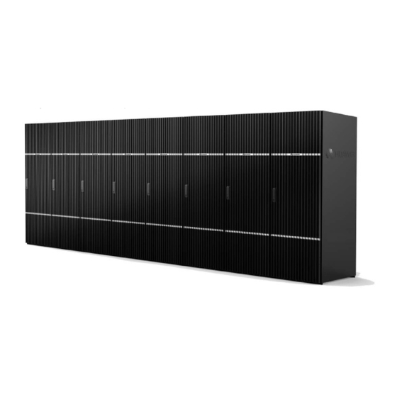
OceanStor HVS85T&HVS88T
Storage System V100R001C00
Quick Installation Guide
Issue: 03
Release date: 2014-08-20
Introduction to the OceanStor HVS85T&HVS88T
As a new-generation storage system designed for large-scale enterprise data centers, HUAWEI OceanStor
HVS85T&HVS88T features massive storage capacity, high-speed data access, high data availability, high
storage utilization, environment protection, and ease of use.
Before You Start
Overview
a
This document guides you through a time-saving process for installing a storage system. For details about the
installation, see the OceanStor HVS85T&HVS88T Storage System V100R001C00 Installation Guide.
Where to get help
b
You can register for a Huawei support account at this website to browse and download valuable information and
sign up for product updates.
Feedback
c
Your feedback is important to us. If you have any comments about this document, please submit them to us on
http://support.huawei.com/enterprise.
Copyright ©Huawei Technologies Co., Ltd. 2014
1
All rights reserved.
Advertisement
Table of Contents

Related Manuals for Huawei OceanStor HVS85T


Summary of Contents for Huawei OceanStor HVS85T
- Page 1 This document guides you through a time-saving process for installing a storage system. For details about the installation, see the OceanStor HVS85T&HVS88T Storage System V100R001C00 Installation Guide. Where to get help You can register for a Huawei support account at this website to browse and download valuable information and sign up for product updates. Feedback Your feedback is important to us.
-
Page 2: Safety Information
Safety Information Do not operate devices or handle cables on a stormy day. To avoid eye injuries, do not look into the optical outlets without eye protection. CAUTION Before you handle devices, wear ESD clothes, a pair of ESD gloves, or an ESD wrist strap and remove conductive objects such as ornaments and watches. - Page 3 1 Installation Preparations Checking installation tools The following installation tools are required: Phillips screwdriver (M3 to M6) Diagonal pliers Adjustable wrench Checking components System bay 2 to 7 System bay 0 System bay 1 Disk bay Multi-mode optical Ground cable mini SAS cable Network cable...
- Page 4 2 Planning Installation Positions (on Raised Floor) Planning positions of bays on the floor Configuration HVS85T HVS88T 2.5-inch disks: four system bays 2.5-inch disks: eight system bays Full 3.5-inch disks: four system bays and two 3.5-inch disks: eight system bays and configuration disk bays two disk bays...
- Page 5 Scenario 2: distributed layout Planning positions of holes on the floor (only for underfloor cabling) Unit: mm...
- Page 6 3 Installing Bays (Optional) Removing side panels Do this procedure only when your storage system is configured with system bays and disk bays. In this case, there is one system bay and one disk bay placed beside each other. You need to remove the system bay side panel against the disk bay and the disk bay side panel against the system bay before installation so that SAS cables can be routed between the two bays.
- Page 7 3 Installing Bays Securing bays Use an adjustable wrench to extend the leveling caster until the caster are not touching the ground and the bay is level. NOTICE Leave a 6 mm to 8 mm space between every two bays so that the front door of the bay on the right can move free when the front door of the bay on the left is fully open.
- Page 8 3 Installing Bays Connecting bays The connecting plates are delivered with the bays. Obtain the connecting plates at the bay bottom near the rear door. Connecting two bays needs six connecting plates (two at the top, two at the front and two at the back).
-
Page 9: Connecting Cables
4 Connecting Cables Routing cables between bays Route the SAS cables between the adjacent system bay and disk bay, as shown in the left figure. Perform this step only when your storage system has system bays and disk bays. Route cross-bay network cables, optical fiber cables, and AOCs overhead, as shown in the following figure. - Page 10 4 Connecting Cables Connecting cables for the SVP and the engine...
- Page 11 4 Connecting Cables Connecting the SVP to the engines using network cables If your storage system has only one system bay, skip this procedure because the cables between the SVP and engine are connected before delivery. Otherwise, you must connect the SVP to the two controllers of each engine in a daisy chain manner.
- Page 12 4 Connecting Cables Connecting the data switches to the engines using AOCs If your system has only one system bay, skip this procedure because there are no data switches. Otherwise, you must connect each of the two data switching modules of one engine to both data switches.
- Page 13 4 Connecting Cables Connecting SAS cables (system bays and disk bays exist)
- Page 14 4 Connecting Cables Connecting engines to application servers Connect each engine to an application server through host ports (1 Gbit/s iSCSI, 10 Gbit/s TOE, 10 Gbit/s FCoE, or 8 Gbit/s Fibre Channel). Scenario 1: direct connection Scenario 2: connection through a switch...
- Page 15 4 Connecting Cables Connecting the SVP to a maintenance terminal Connecting ground cables All devices in a bay are connected to ground terminals on the bay before delivery. Connect each bay to a ground bar in the equipment room using a ground cable.
-
Page 16: Checking Hardware Installation
4 Connecting Cables Connecting the PDU power cable Take the PDU connector out from the accessories, assemble the connector as shown in the following figures. If the site is already available PDU socket, please skip this step. Connect the connector to an external power source. 5 Checking Hardware Installation Checking device installation Check Item... -
Page 17: Powering On The Storage System
6 Powering On the Storage System Power-On procedure Follow basic rules for the system power-on sequence: •If the system includes disk bays, they must be powered on before the system bays. •System bays must be powered on in ascending order from system bay 0 to system bay n. •In a scenario with multiple controllers, all the controllers must be powered on with three minutes. - Page 18 6 Powering On the Storage System Press the power button switch of engine Power on the system by pressing any button on the controller‘s power switch. When the engine is powered on, disk enclosures will start. The process requires 5-15 minutes. Power-on verification When the storage system is powering on, the status indicator on the front door of system bay 0 is blinking green.
-
Page 19: Contacting Huawei Technical Support
4. Log in OceanStor DeviceManager and modify the administrator password of storage system in SVP. 5. (Optional) Import the license file. For details about initializing the storage system, see the OceanStor HVS85T&HVS88T Storage System V100R001C00 Installation Guide. The default user name and password of the storage system are admin and Admin@storage.