Advertisement
This manual contains
important safety information
and must be made available
to personnel who operate and
maintain this machine.
C.C.N.
: 22135917
REV
: E
DATE
: JANUARY 2005
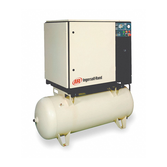
SSR UP6 15, UP6 20, UP6 25, UP6 30
OPTIONS MANUAL
Intellisys Option
Dryer Option
High Dust Option
Outdoor Module Option
PORO Option
60Hz
Advertisement
Table of Contents

Related Manuals for Ingersoll-Rand SSR UP6 15


Summary of Contents for Ingersoll-Rand SSR UP6 15
- Page 1 SSR UP6 15, UP6 20, UP6 25, UP6 30 60Hz OPTIONS MANUAL Intellisys Option Dryer Option High Dust Option Outdoor Module Option PORO Option This manual contains important safety information and must be made available to personnel who operate and maintain this machine.
-
Page 3: Table Of Contents
German Greek 45 PORO OPTION – ELECTRO–PNEUMATIC English Spanish 49 PORO OPTION – INTELLISYS Estonian Finnish French Hungarian Italian Lithuanian Latvian, Lettish Maltese Dutch Norwegian Polish Portuguese Slovak Slovenian Swedish Chinese SSR UP6 15, UP6 20, UP6 25, UP6 30... -
Page 4: Foreword
Ingersoll–Rand reserves the right to make changes and Company USA. improvements to products without notice and without incurring any obligation to make such changes or add such improvements to products sold previously. © COPYRIGHT 2005 INGERSOLL–RAND COMPANY SSR UP6 15, UP6 20, UP6 25, UP6 30... -
Page 5: Decals
Do not use fork lift truck from this side. Emergency stop. On (power). Off (power). AUTOMATIC RESTART MAINTENANCE MAINTENANCE PROHIBITED FRAGILE KEEP DRY THIS WAY UP USE NO HOOKS NO SIDE CLAMPS HOURS SSR UP6 15, UP6 20, UP6 25, UP6 30... - Page 6 Use ULTRA–Plus Coolant only POWER INSPECT Failure to use the specified coolant may result in damage to the machine Every X months, if sooner than required by CHANGE / REPLACE CLEAN operating hours MOISTURE SSR UP6 15, UP6 20, UP6 25, UP6 30...
- Page 7 Can cause severe injury or death. Do not operate without guard in place. Disconnect power before servicing. Lockout/Tagout machine. Air flow exhaust may contain flying debris. Safety protection should be worn at all times. SSR UP6 15, UP6 20, UP6 25, UP6 30...
- Page 8 Ensure that the machine is operating at the rated pressure and that the rated pressure is known to all relevant personnel. SSR UP6 15, UP6 20, UP6 25, UP6 30...
-
Page 9: Safety
Ingersoll–Rand and its associated distributors are happy to advise and assist in these matters. For further information, consult Material Data Sheets CCN 88303979 for ULTRA–Plus Coolant. SSR UP6 15, UP6 20, UP6 25, UP6 30... - Page 10 Make sure that all protective covers are in place. 1. Press ‘Unloaded Stop’[25]. The compressor will unload then stop. STARTING 2. Turn off electrical isolator. Press ‘Start’ [24]. The compressor will start and then load automatically. SSR UP6 15, UP6 20, UP6 25, UP6 30...
- Page 11 26 EMERGENCY STOP This button when depressed will stop the compressor immediately 12 L.E.D.–Set on line pressure. and display an emergency stop alarm message. 13 L.E.D.–Select control mode. 14 L.E.D.–Set star delta time. SSR UP6 15, UP6 20, UP6 25, UP6 30...
- Page 12 (i.e. 223°F (106°C)). pressure setting, when the compressor then changes to the Off line control position and operates with the receiver vented. SSR UP6 15, UP6 20, UP6 25, UP6 30...
-
Page 13: Intellisys Option
This alarm is active only if the remote start/stop is enabled. EMERGENCY STOP The emergency stop button is engaged. LOW SUMP PRESSURE The sump pressure drops below 15 psi (1 bar) during normal operation. SSR UP6 15, UP6 20, UP6 25, UP6 30... - Page 14 INTELLISYS OPTION ELECTRICAL SCHEMATIC – DOL WITH INTELLISYS CONTROL SSR UP6 15, UP6 20, UP6 25, UP6 30...
- Page 15 Valve, solenoid (line / sump) N.C All wiring to be in accordance with local codes. Remote start (Optional) Remote stop (Optional) Common fault output PORO Power out restart (Optional) 2ATT Temperature sensor 3APT Pressure sensor SSR UP6 15, UP6 20, UP6 25, UP6 30...
- Page 16 INTELLISYS OPTION ELECTRICAL SCHEMATIC – STAR DELTA WITH INTELLISYS CONTROL SSR UP6 15, UP6 20, UP6 25, UP6 30...
- Page 17 All wiring to be in accordance with local codes. Remote start Blue – 16 Volts AC (Optional) Remote stop (Optional) Common fault output PORO Power out restart (Optional) 2ATT Temperature sensor 3APT Pressure sensor Contactor (wye / star) SSR UP6 15, UP6 20, UP6 25, UP6 30...
- Page 18 INTELLISYS OPTION PIPING AND INSTRUMENTATION WITH INTELLISYS CONTROL SSR UP6 15, UP6 20, UP6 25, UP6 30...
- Page 19 34.Sensor temperature, Intellisys Option, replaces 12 9. Aftercooler 10.Gauge, pressure 11.Switch, discharge pressure Air/Coolant 12.Switch, temperature 13.Filter, coolant Coolant 14.Thermostat Condensate 15.Cooler Component boundary 16.Relay, overload Motor Refrigerant 17.Valve, safety Option SSR UP6 15, UP6 20, UP6 25, UP6 30...
- Page 20 4. Connector 13.Adaptor 5. Combination block 14.Intake valve assembly 6. Elbow 7. Tee, male run NOTES: 8. Reducer bushing A. Tubing 3/8 inch 9. Valve, solenoid (Blowdown) B. Tubing 1/4 inch SSR UP6 15, UP6 20, UP6 25, UP6 30...
- Page 21 Grommet 22177174 Cabinet 39156393 Connector 96737564 39156419 Connector 96743182 Screw 54774997 Bush 85584340 Latch 39404165 ‘O’ Ring 92829308 22131148 Decal 96703756 39155478 Elbow 22128763 Controller, INTELLISYS * Not illustrated 22091193 Hinge SSR UP6 15, UP6 20, UP6 25, UP6 30...
- Page 22 Contactor – C37 39186093 Plug 22074033 Fuse 6 position 2.0A 125–250V 22056741 Rail 32342099 Fuse 1.5A 600V 39251988 Relay, overload 39491519 Transformer 39479035 Fuse, holder * Not illustrated 39480504 Fuse, holder SSR UP6 15, UP6 20, UP6 25, UP6 30...
- Page 23 Contactor – C43 39186093 Plug 22074033 Fuse 6 position 2.0A 125–250V 22056741 Rail 32342099 Fuse 1.5A 600V 39251079 Relay, overload 39491519 Transformer 39479035 Fuse, holder * Not illustrated 39480504 Fuse, holder SSR UP6 15, UP6 20, UP6 25, UP6 30...
- Page 24 Contactor – C85 39186093 Plug 22074033 Fuse 6 position 2.0A 125–250V 22056741 Rail 32342099 Fuse 1.5A 600V 39251087 Relay, overload 39491519 Transformer 39479035 Fuse, holder * Not illustrated 39480504 Fuse, holder SSR UP6 15, UP6 20, UP6 25, UP6 30...
- Page 25 5 position 22074033 Fuse 2.0A 125–250V 39186093 Plug 6 position 32342099 Fuse 1.5A 600V 22056741 Rail 39251095 Relay, overload 39479035 Fuse, holder 39491519 Transformer 39480504 Fuse, holder * Not illustrated 39251434 SSR UP6 15, UP6 20, UP6 25, UP6 30...
- Page 26 Contactor – C60 6 position 22074033 Fuse 22056741 Rail 2.0A 125–250V 39251087 Relay, overload 32342099 Fuse 1.5A 600V 39203443 Suppressor 39491519 Transformer 39479035 Fuse, holder * Not illustrated 39480504 Fuse, holder 39333257 Interlock SSR UP6 15, UP6 20, UP6 25, UP6 30...
- Page 27 Plug 22074033 Fuse 6 position 2.0A 125–250V 22056741 Rail 32342099 Fuse 1.5A 600V 39255591 Relay, overload 39203443 Suppressor 39479035 Fuse, holder 39491519 Transformer 39480504 Fuse, holder * Not illustrated 39333257 Interlock SSR UP6 15, UP6 20, UP6 25, UP6 30...
- Page 28 6 position 2.0A 125–250V 22056741 Rail 32342099 Fuse 1.5A 600V 39255591 Relay, overload 39203443 Suppressor 39479035 Fuse, holder 39313143 Transformer 39480504 Fuse, holder * Not illustrated 39333257 Interlock 32342123 Lug, power grounding SSR UP6 15, UP6 20, UP6 25, UP6 30...
- Page 29 Contactor – C43 6 position 22074033 Fuse 22056741 Rail 2.0A 125–250V 39251079 Relay, overload 32342099 Fuse 39203443 Suppressor 1.5A 600V 39491519 Transformer 39479035 Fuse, holder * Not illustrated 39480504 Fuse, holder 39333257 Interlock SSR UP6 15, UP6 20, UP6 25, UP6 30...
- Page 30 22074033 Fuse 22056741 Rail 2.0A 125–250V 39251988 Relay, overload 32342099 Fuse 39203443 Suppressor 1.5A 600V 39491519 Transformer 39479035 Fuse, holder 220/230V & 440/460V 39480504 Fuse, holder * Not illustrated 39333257 Interlock SSR UP6 15, UP6 20, UP6 25, UP6 30...
- Page 31 6 position 22074033 Fuse 22056741 Rail 2.0A 125–250V 39251988 Relay, overload 32342099 Fuse 39203443 Suppressor 1.5A 600V 39313143 Transformer 39479035 Fuse, holder 380V 39480504 Fuse, holder * Not illustrated 39333257 Interlock SSR UP6 15, UP6 20, UP6 25, UP6 30...
-
Page 32: Dryer Option
After stopping the dryer, wait at least 3 minutes before starting it again. Do not operate with valves in positions other than those shown here. This may pressurize dryer with no air flow. SSR UP6 15, UP6 20, UP6 25, UP6 30... - Page 33 In order to ensure optimum compressed air quality the filter element should be replaced as follows. (Used filter elements must be disposed of in accordance with local regulations.) Use only genuine Ingersoll–Rand replacement elements. SSR UP6 15, UP6 20, UP6 25, UP6 30...
- Page 34 The unit must only be disassembled by a refrigerant specialist. Refrigerant liquid and lubricating oil inside the refrigeration circuit must be recovered in compliance with current norms in the country where the machine is installed. SSR UP6 15, UP6 20, UP6 25, UP6 30...
- Page 35 3. During the unit guarantee period, the Schrader valve can be used by authorized staff only, otherwise any damage caused by a wrong refrigerant recharge will invalidate warranty. SSR UP6 15, UP6 20, UP6 25, UP6 30...
- Page 36 Fork lift openings Fork lift hole covers must be installed after unit is in place to Q Dryer On/Off switch reduce noise and ensure proper cooling of package) R Dew point indicator SSR UP6 15, UP6 20, UP6 25, UP6 30...
- Page 37 0.25 inch BSPT air filter drain Fork lift openings 1.00 inch NPT plug Filter restriction indicator Air receiver (120 gallons) Dryer On/Off switch Automatic drain valve Dew point indicator Valve, drain Button, emergency stop SSR UP6 15, UP6 20, UP6 25, UP6 30...
- Page 38 0.25 inch BSPT air filter drain Fork lift openings 1.00 inch NPT plug Filter restriction indicator Air receiver (240 gallons) Dryer On/Off switch Automatic drain valve Dew point indicator Valve, drain Button, emergency stop SSR UP6 15, UP6 20, UP6 25, UP6 30...
- Page 39 4 Moisture separator 5. Valve, autodrain Air/Coolant 6 Receiver, air 7. Valve, drain Coolant 8. Indicator, dew point colour Condensate 9 Valve, expansion Component boundary 10 Filter, refrigerant Refrigerant 11.Condenser Option SSR UP6 15, UP6 20, UP6 25, UP6 30...
- Page 40 (UP6 25, UP6 30, UP6 18–HA, UP6 20–HA, UP6 20–HA Only) QF Residual current circuit – breaker (by installer) 10. Condensate drain (complete) 11. Drain valve 12. O–Ring 19. High pressure switch SSR UP6 15, UP6 20, UP6 25, UP6 30...
- Page 41 22067292 Panel 92368687 Setscrew 22100648 Bracket 22134159 Hose assembly 60Hz 22099295 Panel 22099303 Panel 95954269 95937520 Connector 22098750 Valve, ball 60HZ 95953576 Nipple 22100549 Tube assembly 95996153 Connector 22070304 Bracket 96737564 SSR UP6 15, UP6 20, UP6 25, UP6 30...
- Page 42 85583367 Grommet 96742689 Screw 39124813 Tube (Nylon) 96742689 Plug 54514583 Fitting 95937652 Elbow 22132971 Adaptor 22070825 Tube assembly 95928040 Nipple 95937520 Connector 39155478 Elbow 22101083 Separator, water 37143542 Elbow 22098859 Connector SSR UP6 15, UP6 20, UP6 25, UP6 30...
- Page 43 DRYER OPTION Fig.1 Fig. 2a Fig.2b Fig. 2c SSR UP6 15, UP6 20, UP6 25, UP6 30...
- Page 44 Air Filter O–Ring Set 38029187 38029187 38029187 Air Filter Fitting High pressure switch 38333209 38333209 38333209 38034187 38034187 38034187 Refigerant 134a, 30lb Bottle * Must have EPA certified technician to order SSR UP6 15, UP6 20, UP6 25, UP6 30...
-
Page 45: High Dust Filter Option
HIGH DUST FILTER OPTION Item Qty. Description Item Qty. Description 36897999 Filter 96712153 Screw 35393685 Element, air filter 22155345 Hose 22245534 Bracket 22153647 Pipe 35295799 Clamp 92368687 Screw 89295935 Hose SSR UP6 15, UP6 20, UP6 25, UP6 30... -
Page 46: Out Door Module Option
OUT DOOR MODULE OPTION Item Qty. Description Item Qty. Description 22134597 Cover 22127328 22127500 Louvre 22053730 Louvre 92368687 Screw SSR UP6 15, UP6 20, UP6 25, UP6 30... -
Page 47: Poro Option - Electro-Pneumatic
4. Open the main disconnect to remove power from the compressor. 5. Close the main disconnect to reapply power to the compressor. The horn will sound for ten seconds; then the compressor will start automatically. SSR UP6 15, UP6 20, UP6 25, UP6 30... - Page 48 PORO OPTION – ELECTRO–PNEUMATIC SSR UP6 15, UP6 20, UP6 25, UP6 30...
- Page 49 Decal: PORO 39194097 Decal: Power Out Restart Option 22388037 Decal: Schematic 39331954 DIN rail 35275494 39108949 Locknut 22396618 Instructions 39100136 Horn, Weather Resistant 39133467 Mount 95785192 Nipple 39146733 Plug 39203443 Suppressor SSR UP6 15, UP6 20, UP6 25, UP6 30...
- Page 50 DESCRIPTION 39252937 Block, end stop 39309554 Tape, adhesive 35246131 Terminal 39204763 1.2m (4ft) Wire, Blue 16 Ga 39129085 1.2m (4ft) Wire, Red 16 Ga 39146790 1.2m (4ft) Wire, Green 16 Ga SSR UP6 15, UP6 20, UP6 25, UP6 30...
-
Page 51: Poro Option - Intellisys
7. Press SET and the display will flash twice indicating the change has been made. 8. Push the DISPLAY SELECT BUTTON or wait 30 seconds for the controller to automatically exit the set routine. The display returns to READY TO START. SSR UP6 15, UP6 20, UP6 25, UP6 30... - Page 52 PORO OPTION – INTELLISYS Item Qty. Description Item Qty. Description 39194097 Option, Module 39108949 Locknut 35275494 Connector, bulkhead 39146733 Plug 95934279 Nipple 39100136 Horn SSR UP6 15, UP6 20, UP6 25, UP6 30...
Need help?
Do you have a question about the SSR UP6 15 and is the answer not in the manual?
Questions and answers