Advertisement
Quick Links
22
W A L L H U N G S A N I T A R Y W A R E
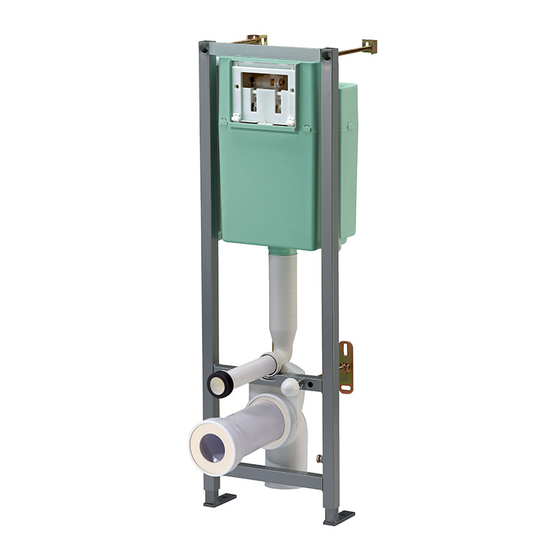
B C m V E R S O 3 5 0
W A L L m O U n T E D V E R S I O n
| TIN |
DE SC R IP TI O n
◗ For installing wall hung standard, extented or compact pan
◗ Wall mounting frame bearing a 400kg load
◗ Steel tubes structure, 30x30x1,5mm, electro-welded and anti-
corrosion
treated, epoxy paint guaranteed 25 years (withstands
200 hours in saline mist)
◗ Feet are made from one epoxy painted steel plate (100x30x8mm)
and one electro-welded epoxy painted steel tubes (25x25x3mm),
fixed to the floor by 2 plugs and 2 bichromated screw plugs
◗ Pan wall fixing thanks to 2 brackets held by 4 plugs and 4
bichromated screw plugs
◗ Fixed to the wall using 2 fixing brackets, held in place by 2 plugs
and 2 bichromated screw plugs.
◗ 6l. insulated Verso 350 cistern
be withdrawn through command plate window
◗ Adjustable double flush
◗ Adjustable noiseless
2010: water saving and silent float valve OD 95L as an option
◗ Mechanical or infra-red double or simple flush front commands,
see choice page 54
◗ Network water connection can be made on the inside or on the
outside of the cistern. Stop cock section
1/2" F.
◗ Drainage accessories can be straight or 90° bent. Made from PVC
or PEHD. Available sections are 90mm., 100mm. and 110mm..
Bent pipe is fixed on the frame by simply clipping it. See choice
page 106
◗ Pan connection set:
- Drain straight pipe for connecting pan to bent pipe can be
made from PVC or PEHD. Diameter is 100mm..
- Supply straight pipe for connecting cistern to pan.
- Pan fixing accessories
See choice page 106
◗ Cladding reservation and protection accessories
bCM Verso 350
S UPP L E m EnT S :
Command plates
Décofast
Meubleo
Accessories
Pan connexion set
Download products information from www.siamp.com
, from which components can
flush valve, 3l./6l. factory preset.
float valve, 6l. factory preset. From April,
can be 3/8" M or
Packing
Packing
Nb
M
kg
3
Carton
1
0,07
15,82
Palette
quantity
20
(see page 54)
(see page 103)
(see page 104)
(see page 106)
(see page 106)
142/147 ~ 245 mm
180 / 230 mm
I
II
I = 142/147
II = 16
100 mm
III = 400
500 mm
IV = < 185 mm
V = 1100
1300 mm
97 mm
245 mm
Advertisement

Related Manuals for Siamp VERSO BCM 350


Summary of Contents for Siamp VERSO BCM 350
- Page 1 IV = < 185 mm Command plates (see page 54) Décofast (see page 103) V = 1100 1300 mm Meubleo (see page 104) Accessories (see page 106) Pan connexion set (see page 106) 97 mm Download products information from www.siamp.com...
- Page 2 CISTERN FRAME VERSO BCM 350 ASSEMBLY AND MAINTENANCE MANUAL...
- Page 3 DESCRIPTION...
- Page 4 Float valve Flexible sheaths (x 2) Pipe attaching collar Stopcock with fibre joint Toilet bowl attaching rods (x 2) Mechanism Setscrew (x 2) PSE template Adjustable foot (x 2) Supply bend Screw plug (x 8) Supply bend cap Plug (x 8) Toilet pipe cap Toilet bowl stud attaching tab (x 2) Supply sleeve...
-
Page 5: Installation Types
INSTALLATION TYPES ➊ Wall fixing EFFECTIVE DIMENSIONS I - Frame depth = from 142 to 245 mm straight outlet from 147 to 245 mm bent outlet II - Cladding thickness = from 16 to 100 mm III - Height = Adjustable from 1080 to 1280 mm IV - Height of toilet bowl = 400 mm (finished floor level) V - Maximum thickness of finished flooring = 185 mm... - Page 6 I - ASSEMBLING THE TOILET BOWL ATTACHING RODS AND WALL FIXING ➎ ➏ ➊ ➋ Measure the center distance of the toilet bowl (A) ➊ ➋ Insert the rods (I) into the holes of the frame, corresponding to the center distance ➌...
- Page 7 III - PREPARING FOR ATTACHMENT ➌ ➋ ➊ Mark the drilling points (6 for wall and 2 for floor) ➋ Remove the frame and drill to a depth of 70 mm at the least, using an 10 mm diameter drill bit ➊...
-
Page 8: Water Supply Connection
V - ATTACHING THE FRAME ➊ Attach the frame definitively VI - WATER SUPPLY CONNECTION ➊ Frame ➊ Remove the frame by Frame lifting the two locks ➋ Connect your pipe to the shut-off valve (b) either using the dual cone supplied or directly with Locks the nuts provided on the... - Page 9 VII - TESTING WITH WATER ➎ ➊ ➌ ➏ Insert the supply sleeve (h) and ➊ the drain sleeve on the toilet bowl Position the toilet bowl on the ➋ frame ➌ Turn on the water using the shut- ➍ off valve (b) and wait until the toilet bowl fills ➏...
- Page 10 VIII - PREPARING THE CLADDING ➊ ➋ Frame ➊ Fit the frame Attach the PSE template (d) to the frame using ➋ the two grey screws provided in the control panel box Fit the caps (f) and (g) on the supply bend (e) and ➌...
- Page 11 X - TOILET BOWL CONNECTION Read bowl and toilet seat instructions before intalling the cistern frame. ➊ Using a rule placed as shown in the above drawing, ➋ Remove the sleeves from the toilet bowl and fit them draw a mark on the toilet bowl side, on the two to the frame.
- Page 12 X - CONNECTING THE TOILET BOWL (cont’d) Deburr the cut pipes using a file ➏ Measure the thickness at the rear of the toilet ➐ bowl (B) ➑ If necessar y, cut the attaching rods (I) so that the part protruding from the wall measures (B) + 20 mm Shorten the flexible sheaths (j) so that the part ➒...
- Page 13 XI - ATTACHING THE TOILET BOWL When the toilet bowl is cor rectly ➊ positioned, attach it using the kit (i) complying with the part stacking order: i = centering washer ii = metal washer iii = nut iv = cover XII - INSTALLING THE CONTROL PANEL ➊...
- Page 14 XII - POSITION IN THE CONTROL PANEL (cont’d) ➊ Adjust operating screws so that size ( C ) is 31 mm. NB : (C) = form the outside of the collar to the head of the screw. Place the command plate on the ➋...
-
Page 15: Maintenance Operations
MAINTENANCE OPERATIONS During the use of your BCM 350 flushing cistern, you may be required to maintain VERSO the equipment. I - MAINTENANCE OF THE VALVE (filter cleaning, replacement of membrane) ➊ ➋➌ ➍ ➊ Remove the control panel by lifting it slightly and tilting it forward ➋... - Page 16 MAINTENANCE OPERATIONS (cont’d) II - MECHANISM MAINTENANCE (cleaning or replacement of the seal) Proceed in the same way as for the maintenance of the valve up to point then: ➏ ➊ ➋ ➊ Take off the brace ➋ Grasp the mechanism by the base and remove it from the cistern Spare parts: Seal P/N 34 2332-07 Complete mechanism: P/N 32-4544-07...
- Page 17 VERSO SIAMP and we would like to thank you for your confidence in our products. As expert in technical equipment and accessories for the toilet, SIAMP has taken every possible measure to apply all the necessary care to the design and production of this product, offering a ten-year guarantee except for rubber parts and manpower.
Need help?
Do you have a question about the VERSO BCM 350 and is the answer not in the manual?
Questions and answers