ABB TTF300 Commissioning Instructions
Field-mounted temperature transmitters
Hide thumbs
Also See for TTF300:
- Commissioning instructions (364 pages) ,
- Operating instruction (92 pages) ,
- Manual (48 pages)

Related Manuals for ABB TTF300


Summary of Contents for ABB TTF300
- Page 1 CI/TTF300-EN TTF300 Commissioning Instructions Field-mounted temperature transmitters TTF300...
- Page 3 Fax: +49 621 381 931-29031 automation.service@de.abb.com © Copyright 2011 by ABB Automation Products GmbH Subject to changes without notice This document is protected by copyright. It assists the user in safe and efficient operation of the device. The contents of this document, whether whole or in part, may not be copied or reproduced without prior approval by the copyright holder.
-
Page 4: Table Of Contents
1.4.2 Name plate ..............................6 1.4.3 Name plate: TTF300 - HART ........................6 1.4.4 Name plate: TTF300 - PROFIBUS PA / FOUNDATION Fieldbus ............7 Transport safety information ..........................7 Safety information for electrical installation....................8 Safety information for commissioning ......................8 Operating safety information ..........................8 Returning devices............................8... - Page 5 5.13 TTF300-R1X, intrinsically safe CSA......................32 5.14 TTF300-R2X, non-incendive CSA........................32 5.15 TTF300-R3X, explosion proof CSA......................32 5.16 TTF300-R7X, explosion proof + intrinsically safe CSA ................32 Type B LCD ................................33 Features ...............................33 Specifications ...............................33 Configuration function ..........................33 Ex relevant specifications..........................33 6.4.1 Intrinsic safety ATEX..........................33 6.4.2...
-
Page 6: Safety
Prior to using corrosive and abrasive materials for measurement purposes, the operator must check the level of resistance of all parts coming into contact with the materials to be measured. ABB Automation Products GmbH will gladly support you in selecting the materials, but cannot accept any liability in doing so. -
Page 7: Plates And Symbols
Failure to observe this safety information may result in damage to or destruction of the product and/or other system components. IMPORTANT (NOTE) This symbol indicates operator tips, particularly useful information, or important information about the product or its further uses. It does not indicate a dangerous or damaging situation. CI/TTF300-EN TTF300 EN - 5... -
Page 8: Name Plate
Safety 1.4.2 Name plate 1.4.3 Name plate: TTF300 - HART The name plate is located on the transmitter housing. TTF300 Automation Products GmbH Alzenau Germany 2008 O-Code: TTF300-E1H 2400045678 Ser.-No: 2065342 HW. Rev. 1.06 U = + 11...30 V, I = 4...20 mA, HART SW. -
Page 9: Name Plate: Ttf300 - Profibus Pa / Foundation Fieldbus
Safety 1.4.4 Name plate: TTF300 - PROFIBUS PA / FOUNDATION Fieldbus The name plate is located on the transmitter housing. TTF300 Automation Products GmbH Alzenau Germany 2009 O-Code: TTF300-E1P 2400034561 Ser.-No: 2064388 HW. Rev. 1.00 U = + 9...32 V, I = 12 mA, FISCO SW. -
Page 10: Safety Information For Electrical Installation
According to EC guidelines for hazardous materials, the owner of hazardous waste is responsible for its disposal or must observe the following regulations for shipping purposes: All devices delivered to ABB Automation Products GmbH must be free from any hazardous materials (acids, alkalis, solvents, etc.). -
Page 11: 1.10 Disposal
If it is not possible to dispose of old equipment properly, ABB Service can accept and dispose of returns for a fee. 1.10.2 RoHS Directive 2002/95/EC With the Electrical and Electronic Equipment Act (ElektroG) in Germany, the European Directives 2002/96/EC (WEEE) and 2002/95/EC (RoHS) are translated into national law. -
Page 12: Use In Potentially Explosive Atmospheres
Ex modem into the circuit outside the potentially explosive atmosphere. Ex relevant specifications See Chapter 5, "Ex relevant specifications" page 31. 10 - EN TTF300 CI/TTF300-EN... -
Page 13: Mounting
Attach the wall mount to the wall using Attach the pipe mount to the pipe using 2 pipe 4 screws (Ø 10 mm). clamps (Ø 10 mm). The pipe mount can be attached to a pipe with a maximum diameter of 2.5“. CI/TTF300-EN TTF300 EN - 11... -
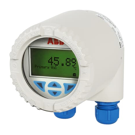
Page 14: Position Of Lcd Indicator
3. Carefully pull the LCD indicator to release it from its holder. 4. Carefully insert the LCD indicator in the required position. 5. Screw the housing cover back on. 6. Loosen the lock screw until the housing cover is firmly in place. 12 - EN TTF300 CI/TTF300-EN... -
Page 15: Electrical Connections
70 mm (2.76 inch) (0.47 inch) (0.33 inch) 20 mm 54 mm (2.13 inch) (0.79 in.) 50 mm (1.97 inch) ~140 mm (5.51 inch) 50 mm (1.97 inch) A00271 Fig. 5 1 End of cable duct CI/TTF300-EN TTF300 EN - 13... -
Page 16: Cable Glands
4.2.2 TTF300 Ex d models without cable gland For delivery of the product variants TTF300-E3... (ATEX Ex d / flameproof enclosure) and TTF300-E4..(ATEX Ex d and Ex ia or flameproof enclosure and intrinsic safety) without cable gland, an approved ATEX Ex d cable gland must be used according to EN 60079-1. -
Page 17: Ttf300 Ex D Models With Standard Cable Gland
Electrical connections 4.2.3 TTF300 EX d models with standard cable gland General information Type Capri Outer diameter of Material ADE 1F threads cable 816674 No. 4 M20 x 1,5 Ø 6 ... 8.5 mm Nickel-plated brass or stainless steel 818674 No. 4 1/2“ NPT Ø... - Page 18 The customer must provide a strain relief device for the cable. Maintenance Check the glands during each maintenance session. If the cable is slack, retighten the cap(s) of the glands. If it is not possible to retighten them, the gland will need to be replaced. 16 - EN TTF300 CI/TTF300-EN...
-
Page 19: Connection For Power Supply Cable/ Sensor Connecting Cable
8. If there is one, carefully insert the LCD indicator in the previous / required position. 9. Screw the housing cover back on. 10. L oosen the lock screw until the housing cover is firmly in place. CI/TTF300-EN TTF300 EN - 17... -
Page 20: Connection Of Sensor Measuring Insets / Connection Diagrams
7 1 x RTD, two-wire circuit, and thermocouple Ground terminals for sensor and 4 1 x thermocouple supply- / signal-cable shield connection Sensor 1 Sensor 2 1) Sensor backup / redundancy, sensor drift monitoring, mean measurement, or differential temperature measurement 18 - EN TTF300 CI/TTF300-EN... -
Page 21: Shielding Of The Signal / Power Supply Cable And The Sensor Connecting Cable
6 Shield insulated from transmitter housing 2 Shield insulated from sensor 7 Power supply cable 3 Sensor connection cable 8 Grounding point 4 Shield grounded via transmitter housing 9 Supply isolator / PCS input 5 Transmitter housing, grounded CI/TTF300-EN TTF300 EN - 19... - Page 22 6 Shield insulated from transmitter housing 2 Shield grounded via sensor 7 Power supply cable 3 Sensor connection cable 8 Grounding point 4 Shield insulated from transmitter housing 9 Supply isolator / PCS input 5 Transmitter housing, grounded 20 - EN TTF300 CI/TTF300-EN...
- Page 23 1 Temperature sensor 5 Transmitter housing, not grounded 2 Shield insulated from sensor 6 Power supply cable 3 Sensor connection cable 7 Grounding point 4 Shields connected electrically via transmitter 8 Supply isolator / PCS input housing CI/TTF300-EN TTF300 EN - 21...
- Page 24 6 Shield insulated from transmitter housing 2 Shield grounded via sensor 7 Power supply cable 3 Sensor connection cable 8 Grounding point 4 Shield insulated from transmitter housing 9 Supply isolator / PCS input 5 Transmitter housing, grounded 22 - EN TTF300 CI/TTF300-EN...
-
Page 25: Electrical Interconnection With Standard Application
When connecting these components, observe the following condition: U + 0.022 A x R Mmin Smin Where Minimum operating voltage of transmitter Mmin Minimum supply voltage of supply isolator / PCS input Smin Line resistance between transmitter and supply isolator CI/TTF300-EN TTF300 EN - 23... -
Page 26: Hart Functionality
When connecting these components, observe the following condition: U + 0.012 A x R Mmin Smin Where Minimum operating voltage of transmitter Mmin Minimum supply voltage of supply isolator / PCS input Smin Line resistance between transmitter and supply isolator 24 - EN TTF300 CI/TTF300-EN... -
Page 27: Electrical Interconnection In Explosion Hazardous Areas
(intrinsically safe equipment) (related equipment) ≥ ≥ ≥ (cable) ≤ (cable) ≤ Field (Ex area) Control room (safe area) A00096 Fig. 16 A Transmitter B Supply isolator / PCS input with supply / Segment coupler CI/TTF300-EN TTF300 EN - 25... -
Page 28: Installation In A Potentially Explosive Atmosphere
Fig. 17 A Sensor C Supply isolator [Ex ia] B Transmitter TTF300 D Interface for LCD indicator The input for the supply isolator must have an "Ex ia" design. When using the transmitter in Zone 0, you must avoid impermissible electrostatic charging of the transmitter (observe the warnings on the device). - Page 29 Fig. 18 A Sensor C Supply isolator [Ex ib] B Transmitter TTF300 D Interface for LCD indicator The input for the supply isolator must have an [Ex ib] design. As the user, it is your responsibility to ensure that the sensor instrumentation meets the requirements of applicable explosion protection standards.
- Page 30 A00129 Fig. 20 A Sensor C Supply isolator B Transmitter TTF300 D Interface for LCD indicator In the event of a disturbance, it must be ensured that the supply voltage cannot exceed the normal voltage by more than 40 %.
- Page 31 Fig. 22 A Sensor C Supply isolator B Transmitter TTF300 D Interface for LCD indicator If you are using the sensor in Zone 0 and the transmitter in Zone 20, the transmitter must conform to category 1D and the circuit must be of the "ia" design.
- Page 32 As the user, it is your responsibility to ensure that sensor instrumentation meets the requirements of applicable Ex standards. The sensor can be installed in Zone 1 or Zone 0. For Zone 0, the circuit must be of the [Ex ia] design. 30 - EN TTF300 CI/TTF300-EN...
-
Page 33: Ex Relevant Specifications
Ex relevant specifications Ex relevant specifications Change from one to two columns Intrinsic safety Ex ia IIC type of protection (part 1) TTF300-E1X, intrinsic safety ATEX TTF300-E1H TTF300-E1P / -H1P Explosion protection TTF300-H1H TTF300-E1F / -H1F Approved for use in Zone 0, 1, and 2... -
Page 34: Ttf300-E5X, Non-Sparking + Dust Explosion Protection Atex
II 3G Ex nA II T6 TTF300-L2P: II 3 D IP 65 T 135 °C Control Drawing: TTF300-L2..P (NI_PS), TTF300-L2..P (NI_AA) TTF300-L2F: ABB manufacturer's declaration in accordance with ATEX Directive Control Drawing: TTF300-L2..F (NI_PS), TTF300-L2..F (NI_AA) Temperature table 5.11 TTF300-L3X, explosion proof FM Temperature... - Page 35 1 Exit / Cancel 3 Scroll forward Max. voltage = 9 V 2 Scroll back 4 Select Short circuit current = 65.2 mA Max. power = 101 W Internal inductance = 0 mH Internal = 0 nF capacitance CI/TTF300-EN TTF300 EN - 33...
- Page 36 = 9V, I i / I < 65.2 mA, P i = 101 mW C i < 0.4 µF, L i = 0 C i = 0.4 µF; L i = 0 Control Drawing: SAP_214 750 Control Drawing: SAP_214 751 34 - EN TTF300 CI/TTF300-EN...
- Page 37 Identification for intended use in potentially explosive atmospheres according Protection ATEX directive (marking in addition to CE marking) IEC standards FM Approvals (US) CSA International (Canada) Important (Notice) All documentation, declarations of conformity, and certificates are available in ABB's download area. www.abb.com/temperature CI/TTF300-EN TTF300 EN - 35...
- Page 38 Appendix 36 - EN TTF300 CI/TTF300-EN...
- Page 40 ABB has Sales & Customer Support expertise in over The Company’s policy is one of continuous product 100 countries worldwide. improvement and the right is reserved to modify the information contained herein without notice. www.abb.com/temperature Printed in the Fed. Rep. of Germany (06.2011) ©...